

Page 1

Multi-Positioning System (MPS) Seat
Instructions for Use
©2008 Otto Bock HealthCare LP • 07101371.1 1/08
Page 2

Page 3

Table of Contents
1 General Information . . . . . . . . . . . . . . . . . . . . . . . . . . . . . .2
1.1 Preface . . . . . . . . . . . . . . . . . . . . . . . . . . . . . . . . . . . . . . . . . 2
1.2 Intended Use . . . . . . . . . . . . . . . . . . . . . . . . . . . . . . . . . . . . . 2
1.3 Declaration of Conformity . . . . . . . . . . . . . . . . . . . . . . . . . . . . 2
1.4 Liability . . . . . . . . . . . . . . . . . . . . . . . . . . . . . . . . . . . . . . . . . 2
1.5 Service and Repairs . . . . . . . . . . . . . . . . . . . . . . . . . . . . . . . . 2
2 Safety Considerations . . . . . . . . . . . . . . . . . . . . . . . . . . . .2
2.1 Symbol Legend . . . . . . . . . . . . . . . . . . . . . . . . . . . . . . . . . . . 2
2.2 General Safety Considerations . . . . . . . . . . . . . . . . . . . . . . . . . 2
3 MPS Seat Overview . . . . . . . . . . . . . . . . . . . . . . . . . . . . . .3
3.1 Fasteners . . . . . . . . . . . . . . . . . . . . . . . . . . . . . . . . . . . . . . . 3
3.2 Footrest . . . . . . . . . . . . . . . . . . . . . . . . . . . . . . . . . . . . . . . . . 3
3.3 Positioning Belts . . . . . . . . . . . . . . . . . . . . . . . . . . . . . . . . . . . 3
4 Preparing MPS Seat for Use . . . . . . . . . . . . . . . . . . . . . . .3
4.1 Attaching the MPS Seat . . . . . . . . . . . . . . . . . . . . . . . . . . . . . 3
4.2 Detaching the MPS Seat . . . . . . . . . . . . . . . . . . . . . . . . . . . . 3
4.3 Headrest . . . . . . . . . . . . . . . . . . . . . . . . . . . . . . . . . . . . . . . . 3
4.4 Sun Canopy . . . . . . . . . . . . . . . . . . . . . . . . . . . . . . . . . . . . . . 3
5 Maintenance and Care . . . . . . . . . . . . . . . . . . . . . . . . . . . .4
6 Adjusting the MPS Seat-For Technicians Only . . . . . . . . . .4
6.1 Seat to Back Angle . . . . . . . . . . . . . . . . . . . . . . . . . . . . . . . . . 4
6.2 Backrest Height . . . . . . . . . . . . . . . . . . . . . . . . . . . . . . . . . . . 4
6.3 Seat Depth . . . . . . . . . . . . . . . . . . . . . . . . . . . . . . . . . . . . . . 4
6.4 Seat Width . . . . . . . . . . . . . . . . . . . . . . . . . . . . . . . . . . . . . . . 5
6.5 Armrest Height and Angle . . . . . . . . . . . . . . . . . . . . . . . . . . . . 5
6.6 Lateral Height and Width . . . . . . . . . . . . . . . . . . . . . . . . . . . . 5
6.7 Lateral Depth (size 2 only) . . . . . . . . . . . . . . . . . . . . . . . . . . . . 5
6.8 Buttery Harness . . . . . . . . . . . . . . . . . . . . . . . . . . . . . . . . . . 6
6.9 Pelvic Positioning Strap . . . . . . . . . . . . . . . . . . . . . . . . . . . . . . 6
6.10 Headrest Height . . . . . . . . . . . . . . . . . . . . . . . . . . . . . . . . . . . 6
6.11 Footplate Height . . . . . . . . . . . . . . . . . . . . . . . . . . . . . . . . . . . 6
6.12 Knee Angle . . . . . . . . . . . . . . . . . . . . . . . . . . . . . . . . . . . . . . 7
6.13 Footplate Dorsi/Plantar-Flexion Adjustment . . . . . . . . . . . . . . . 7
9
7 Accessories . . . . . . . . . . . . . . . . . . . . . . . . . . . . . . . . . . . .7
7.1 Positioning Tray . . . . . . . . . . . . . . . . . . . . . . . . . . . . . . . . . . . 7
7.2 Shoe Holders . . . . . . . . . . . . . . . . . . . . . . . . . . . . . . . . . . . . . 7
7.3 Abduction Block . . . . . . . . . . . . . . . . . . . . . . . . . . . . . . . . . . . 7
7.4 Foot Straps w/ Hook and Loop Closures . . . . . . . . . . . . . . . . . 8
7.5 Footrest Build Up . . . . . . . . . . . . . . . . . . . . . . . . . . . . . . . . . . 8
7.6 Foot Plate Padding . . . . . . . . . . . . . . . . . . . . . . . . . . . . . . . . . 8
7.7 Padded Arm Rests . . . . . . . . . . . . . . . . . . . . . . . . . . . . . . . . . 8
7.8 Curved Swing Away Lateral . . . . . . . . . . . . . . . . . . . . . . . . . . . 8
7.9 Adjustable Winged Headrest . . . . . . . . . . . . . . . . . . . . . . . . . . 8
7.10 Fixed Winged Headrest . . . . . . . . . . . . . . . . . . . . . . . . . . . . . . 8
8 Technical Data . . . . . . . . . . . . . . . . . . . . . . . . . . . . . . . . . .9
9 Warranty . . . . . . . . . . . . . . . . . . . . . . . . . . . . . . . . . . . . . . .9
1
Page 4
1 General Information
English
1.1 Preface
Thank you for choosing the Multi-Positioning System (MPS) Seat for use
with Otto Bock Pediatric Mobility devices.
Before using the MPS Seat, we strongly recommend that you read the
following instructions and become familiar with the handling, function and
use of the product.
If you have any further questions or comments regarding your new MPS
Seat, please contact the Otto Bock Customer Service department in the US
at 800.328.4058, or in Canada at 800.665.3327.
1.2 Intended Use
The Multi-Positioning System (MPS) Seat is intended for use with children
who are unable to walk, need to be transported, and are unable to
operate a wheelchair themselves. The MPS seat can be transferred to
several other Otto Bock mobility bases while retaining the child’s unique
adjustment settings.
1.3 Declaration of Conformity
Otto Bock HealthCare GmbH as manufacturer with sole responsibility
declares that the MPS Seat conforms to the requirements of the 93/42/
EEC Guidelines.
1.4 Liability
The Otto Bock Warranty applies only when the product is used according
to the specied conditions and for the intended purposes, following all
manufacturer’s recommendations (also see our general terms of sale,
delivery and payment—located on our invoice).
1.5 Service and Repairs
Service and repairs on the MPS Seat may only be carried out by Otto Bock
HealthCare suppliers. Should any problems arise, please contact the supplier
of your MPS Seat. Any necessary repairs will be made exclusively with
authentic Otto Bock replacement parts.
2 Safety Considerations
2.1 Symbol Legend
Danger!
Warning messages regarding possible risks of accident
or injury.
Attention!
Warning messages regarding possible technical damages.
Note!
Information regarding operation of the device.
Note!
Information for service staff.
Attention!
Please read the Instructions for Use rst.
2.2 General Safety Considerations
Attention!
Please read instructions for use rst.
It is important that you are familiar with this product and how
to operate it before use.
Danger!
Never leave the child unattended in the MPS Seat.
Danger!
All positioning belts are intended for posture support only. For
vehicle transportation, see separate transportation manual.
Danger!
Never exceed the weight limit of your system. The MPS Seat
supports a child up to 77 lbs (35 kgs).
If you exceed this weight limit, it is possible that
• the child could fall out of the pediatric wheelchair,
• the pediatric wheelchair could tip over
• the caregiver could lose control of the pediatric
wheelchair, causing injury to the user or others.
Refer to the Instructions for Use for your specic pediatric
mobility devices for total frame capacity for those devices.
Attention!
Always consult your authorized healthcare dealer before you
attempt any modications, adjustments or repairs.
2
Attention!
Always check to make sure the seat is properly snapped onto
the seat adapter.
Page 5
3 MPS Seat Overview
Your MPS Seat is designed to grow with your child. But it is important to
work with your dealer to properly adjust the MPS Seat. Only Otto Bock parts
and accessories that are made specically for the MPS Seat should be used.
Use of unauthorized parts or modications will void the warranty and may
cause a safety hazard.
3.1 Fasteners
Attention!
Many of the screws, bolts and nuts on this seat are special
high-strength fasteners. Use of improper fasteners may
cause the seat to fail.
1. ONLY use fasteners provided by an authorized supplier.
2. Over or under tightened fasteners may fail or cause damage to seat parts.
3. If bolts or screws become loose, tighten them immediately.
3.2 Footrest
Attention!
NEVER lift the MPS Seat by the footrest.
The footrest detaches and will not bear the weight of MPS Seat. Lift seat
only by non-detachable parts.
1. At the lowest point, the footrest should be AT LEAST 2 INCHES off the
ground. If set too low, they may get caught on obstacles you can expect
to nd in normal use. This may cause the pediatric wheelchair to tip over.
2. To avoid a trip or fall when you transfer the child:
a. Make sure the child’s feet do not get caught in the space between the
footrest and the pediatric wheelchair frame.
b. Avoid putting weight on the foot rests, as this may cause the pediatric
wheelchair to tip forward.
3.3 Positioning Belts
Danger!
Use positioning belts ONLY to help support the child.
Improper use of these belts may cause severe injury to, or
death of, the child. All belts and harnesses are for positioning
only and should not be used as safety devices during
vehicle transport.
Danger!
Make sure the child does not slide down in the MPS seat.
If this occurs, the child may suffer chest compression or
suffocate due to the pressure from the belts.
1. The belts must be snug, but must not be so tight that they interfere with
breathing. You should be able to slide your open hand, at, between the
belt and the child.
2. NEVER Use Positioning Belts:
a. Without consulting a seating specialist on proper use.
b. As a patient restraint; a restraint requires a doctor’s order.
c. On an occupant who is comatose or agitated.
d. As a motor vehicle restraint. In an accident or sudden stop the child
may be thrown from the seat. The MPS Seat’s positioning belts will not
prevent this and a further injury may result from the belts or straps.
4 Preparing the MPS Seat for Use
4.1 Attaching the MPS Seat
Depending on the mobility base with which it is being used, the MPS seat
can be installed either forward or rear facing. Follow instructions below for
either option.
1. Hold the seat with both hands.
2. With one hand on the top of the backrest and one hand on the front edge
of the seat, angle the seat back approximately 45 degrees.
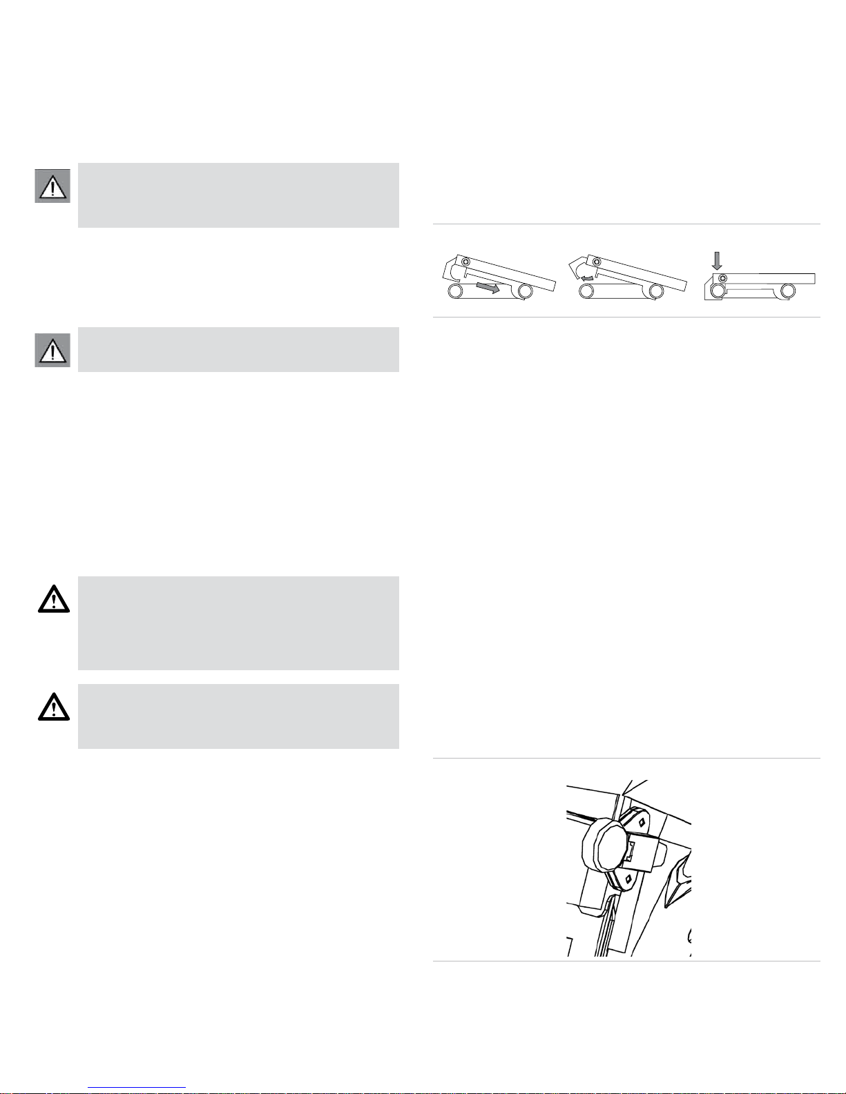
3. Line up the back groove of the seat interface with the back bar of
the seat adapter located on the mobility base (Fig. 1).
Fig. 1
4. Once the back groove is secure, press the front edge of the seat onto the
frame until you hear a click.
5. Shake the seat to make sure that it is securely in place.
Warning: If you do not hear the seat click, it is not securely in place.
4.2 Detaching the MPS Seat
1. From the side of the pediatric mobility device, hold the front edge of the
seat with one hand and place the other hand on the top of the backrest.
2. Reach under the front edge of the seat and locate the lever with
ball handle.
3. Pull lever forward, tip seat back slightly and lift out at an angle.
4.3 Headrest
1. Install vertical tube of headrest hardware into bracket located on backrest.
2. Slide horizontal tube with headrest pad mounted on one end into
receptacle located at the top of the vertical tube.
3. Tighten knob once headrest is positioned correctly. Note: For adjustments
see section 6.10.
4.4 Sun Canopy
1. Loosen set screws on sun canopy brackets.
2. Slide brackets onto sun canopy posts.
3. Tighten bracket set screws at desired height.
4. Insert sun canopy (Fig. 2).
Fig. 2
5. To increase sun canopy height, raise backrest as described in section 6.2.
6. Remove all four screws from the sun canopy posts.
7. Flip up posts.
8. Reattach screws on sun canopy posts and set backrest at desired height.
3
Page 6
5 Maintenance and Care
5.1 Introduction
Proper maintenance will improve performance and extend the useful life of
The MPS Seat.
Clean the MPS Seat regularly, and check frame and upholstery at least every
three months. This will help you nd loose or worn parts and make the MPS
Seat easier and safer to use.
1. Cleaning Upholstery
a. Hand-wash (machine washing may damage fabric).
b. Drip-dry only. DO NOT machine dry as heat will damage fabric.
2. Repair or replace loose, worn, bent or damaged parts before using the
seat. To protect your investment, have all major maintenance and repair
work done by your suppliers.
3. Store the MPS Seat in a clean, dry area. If you fail to do so parts may
rust or corrode.
6 Adjusting the MPS Seat-For Technicians Only
The following adjustments are to be made only by the user’s
clinical specialist.
6.1 Seat to Back Angle
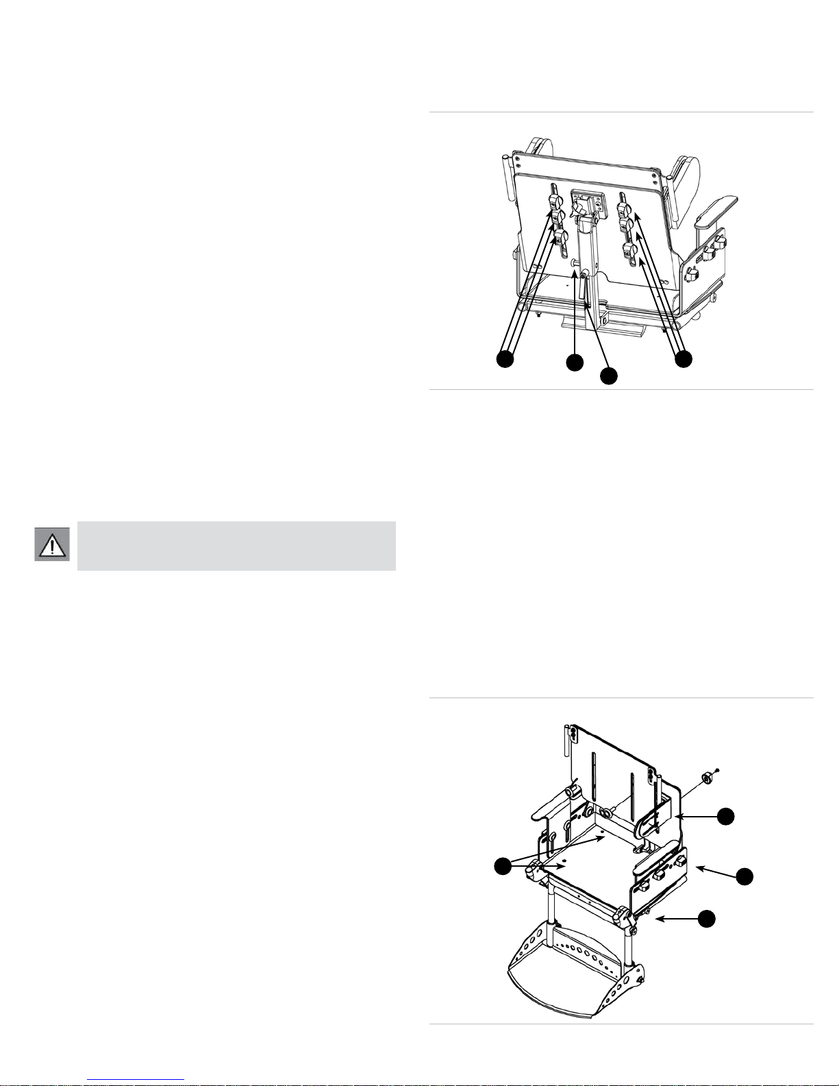
1. Loosen clamping lever by rotating counterclockwise no more than half a
turn (Fig. 3, Pos. A).
2. Pull the spring-loaded recline button with one hand while holding the top
of the backrest with the other hand (Fig. 3, Pos. B).
3. Move seat to desired recline angle and release spring-loaded button.
4. Tighten clamping lever to secure seat angle.
Attention!
Make sure the spring-loaded recline button is fully engaged
when using during vehicle transport.
6.2 Backrest Height
1. Detach upholstery from backrest.
2. Loosen screws inside the six knobs located on rear of backrest
(Fig. 3, Pos. C).
Fig. 3
C
B
A
C
3. Set backrest to desired height. Note: you may need to detach lateral pads
and re-attach them to upper portion of backrest in order to achieve higher
backrest heights.
4. Tighten screws, knobs and re-attach backrest upholstery.
6.3 Seat depth
1. Loosen set screws on either side of seating interface (Fig. 4, Pos. B).
2. Remove seat cushion and seat pan.
3. Loosen four Phillips head screws located in seat pan (Fig. 4, Pos. C).
4. Slide footrest assembly forward to desired depth and tighten set
screws securely.
5. Install seat cushion (including seat pan) at desired location. NOTE: If seat
pan has been extended to furthest position and more depth is required,
remove seat back attachment knobs (Fig. 4, Pos. D) and re-position
backrest to achieve desired depth.
6. Re-install knobs, tighten Phillips head screws (Fig. 4, Pos. C) securely.
Be sure that front lip of cushion ts snugly against front edge of seat pan.
Fig. 4
4
A
C
D
AB
Page 7
7. After adjusting the seat depth, it may be necessary to adjust the position
of the Ischial shelf.
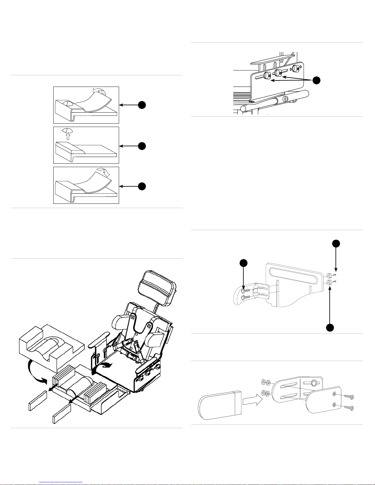
a. To do so, peel back the 1⁄4˝ (.6 cm) layer of top foam far enough to
expose the Ischial shelf completely (Fig. 5, Pos. A).
b. Next peel off the Ischial shelf foam (Fig. 5, Pos. B).
c. Reposition the shelf in the desired location and x it in place using a
spray adhesive (Fig. 5, Pos. C).
d. In addition, the medial knee rise may be modied if necessary using a
razor knife or similar tool.
Fig. 5
A
B
C
8. To increase seat depth and maintain the proper positioning of the Ischial
shelf, insert provided contoured foam piece. Consult your clinician before
making adjustments to the seat.
6.4 Seat Width
1. Remove seat cushion from seat pan by detaching hook and loop closure
located at the back of seat cushion cover (Fig. 6).
Fig. 6
6.5 Armrest Height and Angle
1. Loosen both knobs located under armrest (Fig. 7, Pos. A).
2. Set armrest to desired height and angle and tighten knobs.
Fig. 7
A
6.6 Lateral Height and Width
1. Loosen knobs that hold laterals in place, located on the rear of backrest
(Fig. 8, Pos. B).
2. Set to desired location and tighten knobs.
3. To achieve certain locations you may need to detach the laterals and
re-attach them.
a. If this is necessary, remove Phillips head screw in center of knob
(Fig. 8, Pos. A), and remove knob.
b. Move to desired position, re-install and tighten securely. Note: To
achieve minimum and maximum widths you may need to remove
knob and locking washer at head of screw completely. To adjust for
minimum/maximum width, rotate washer 180° and re-position tab
on washer to opposite side. Positioning tab toward center achieves
minimum width. Tab toward outside achieves maximum width.
(Fig. 8, Pos. C).
Fig. 8
A
C
2. Open cover and remove foam pieces from hip guide pocket until desired
width is achieved. Note: Each foam piece is 1/2˝ (1.2 cm) wide.
3. Pull cover taut and close. Re-attach seat cushion to seat pan with hook
and loop closure.
B
6.7 Lateral Depth (size 2 only)
1. Remove fabric cover, loosen screws, set to desired depth, tighten screws
and re-install cover (Fig. 9).
Fig. 9
5
Page 8
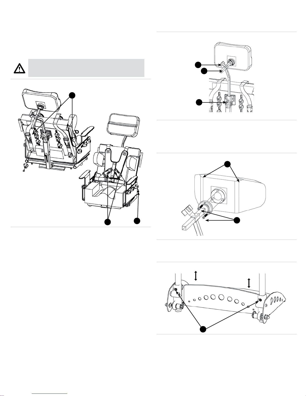
6.8 Buttery Harness
1. Pull nylon shoulder straps in the rear of the back to desired length
(Fig. 10, Pos. A) and/or pull nylon straps on bottom of harness to desired
length (Fig. 10, Pos. B).
2. To open harness, undo the two snaps located in the center of the
harness. Or, release the two plastic buckles located at the bottom of the
harness and pull the harness up over the child’s head.
6.10 Headrest Height
1. Height: Loosen star knob on backrest panel (Fig. 11, Pos. A). Set
headrest to desired height and tighten star knob.
Fig. 11
Fig. 10
Danger!
Be sure to leave an appropriate amount of space between
the harness and the child’s throat to avoid choking.
A
B
C
A
2. Depth: Loosen star knob on headrest (Fig. 11, Pos. B), set to desired
location and tighten knob. To remove excess tubing (Fig. 11, Pos. C),
remove end cap, cut tube and replace cap.
3. Angle: loosen all 3 setscrews located on the collar of the headrest. Set to
desired angle and tighten screws (Fig. 12, Pos. A).
Fig. 12
B
B
C
6.9 Pelvic Positioning Strap
1. To adjust the pelvic positioning strap, pull the “D” ring to desired length. If
greater adjustment is needed, reattach belt using a different grommet hole
on the belt (Fig. 10, Pos. C).
A
6.11 Footplate Height
1. Loosen the two set screws located at the back of the Footplate
(Fig. 13, Pos. A).
Fig. 13
A
2. Set to desired height and tighten set screws. Ensure Footplate is level.
Note: If minimum height is not adequate please see footplate buildup
accessory in section VI.
6
Page 9

6.12 Knee Angle
1. Loosen knob located at the top of the footrest (Fig. 14, Pos. A).
2. Elevate footrest to desired location and tighten knob. Note: The
telescoping leg rest allows for adjustments in knee angle without having
to readjust the footplate height.
Fig. 14
A
B
6.13 Footplate Dorsi/Plantar-Flexion Adjustment
1. Loosen the two nuts on both sides of the footplate.
2. Pivot the footplate to desired angle and re-tighten nuts (Fig. 14, Pos. B).
7.2 Shoe Holders
1. Drill holes (#7 or .20˝ or 3/64˝ (1.1 mm)) in the footplate in the desired
location.
2. Attach foot plate using the provided hardware (Fig. 16).
Fig. 16
7.3 Abduction Block
1. To mount the abduction block, carefully peel back the top layer or 1/4˝
(6 mm) foam sheathing (Fig. 17, Pos. A).
Fig. 17
A
7 Accessories
7.1 Positioning Tray
1. Attach tray as shown, making sure that the rails on the bottom of the tray
slide securely onto the arm rests (see Figure 15).
Fig. 15
2. Attach the straps around the back of the seat as indicated, and adjust to
the desired length.
Note!
Armrest pads must be removed to use positioning tray.
B
C
2. Using a knife, remove existing medical knee support (Fig. 17, Pos. B).
3. Replace the top layer 1/4˝ (6 mm) foam sheathing (Fig. 17, Pos. C).
4. Connect the abductor block to the base (Fig. 18, Pos. B). Mount
abduction block to front edge of seat using hardware provided.
Fig. 18
A
B
7
Page 10
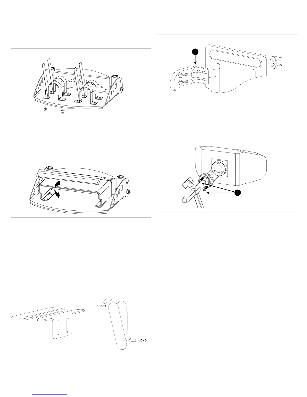
7.4 Foot Straps w/ Hook and Loop Closures
1. Drill holes (drill size H or. 266˝ or 17/64˝ (6.7 mm)) in the footplate in the
desired location (Fig. 19).
2. Attach foot straps using hardware provided.
3. Make sure the ap closures are on the outside (Fig. 19).
Fig. 19
7.5 Footrest Build Up
1. Center Footplate Build Up on the footrest and mark holes through it with
a scribe.
2. Drill holes with a 7⁄32˝ (5.5 mm) bit. Attach Footplate Build Up with the
provided hardware (Fig. 20).
Fig. 20
7.8 Curved Swing Away Lateral
1. Attach lateral using provided hardware as shown below (Fig. 22).
2. Press red button to release lateral (Fig. 22, Pos. A).
Fig. 22
A
7.9 Adjustable Winged Headrest
1. Attach the headrest using the hardware provided.
2. To adjust the headrest, remove the cover and loosen the two bolts
(Fig. 23, Pos. A).
3. Set to desired angle and tighten bolts.
Fig. 23
7.6 Foot Plate Padding
1. Attach adhesive hook and loop closure.
2. Insert the small ap between the footplate buildup and the heel plate and
fasten underneath.
3. Wrap pad around the front of the footplate buildup and attach hook and
loop closure underneath (Fig. 20).
7.7 Padded Arm Rests
1. Attach one end of the pad to the long end of the armrest, and pull the
other end over the short end of the armrest (Fig. 21).
Fig. 21
A
7.10 Fixed Winged Headrest
1. Attach the headrest using the hardware provided.
NOTE: Armrest pads must be removed to use positioning tray.
8
Page 11
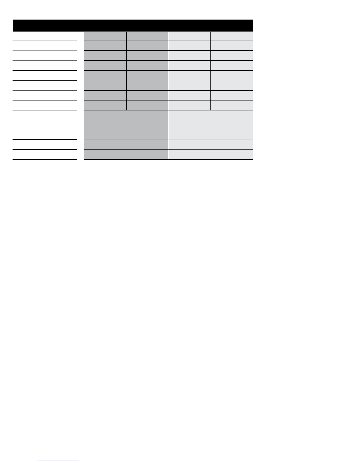
8 Technical Data
Dimensions and Weights Size 1 Base (Model 3291) Size 2 Base (Model 3293)
MInim um Max im um MInim um Maximum
Seat depth 53⁄4 i n. (1 5c m) 121⁄2 i n. (3 2c m) 83⁄4 i n. (2 2c m) 151⁄2 i n. (3 9c m)
Seat width 6 in.(15cm) 101⁄4 i n. (2 6c m) 8 in.(20cm) 13 in. (33cm)
Seat back height 91⁄2 i n.(24cm) 163⁄4 i n. (4 3c m) 111⁄2 i n.(29cm) 201⁄2 i n. (5 2c m)
Seat back recline 90° 140° 90° 140 °
Lateral height adjustmen t 6 in. ( 15 cm) 143⁄4 i n. (3 7c m) 6 in.1 (5 cm) 19 i n. (48c m)
Lateral width adjustment 71⁄2 i n. (1 9c m) 101⁄2 i n. (2 7c m) 8 in. ( 20 cm) 121⁄2 i n.(32cm)
Armrest height adj. 31⁄2 i n. (9 cm ) 51⁄2 i n. (1 4c m) 53⁄4 i n. (1 5c m) 73⁄4 i n. (2 0c m)
Footrest vertical adj. 9 in. (23cm) 1 51⁄2 i n. (3 9c m) 9 in. ( 23 cm) 151⁄2 i n. (3 9c m)
Headrest width and height 71⁄2 i n. x 61⁄2 i n. (1 9c m x 17cm) 91⁄2 i n. x 61⁄2 i n. (2 4c m x 17cm)
Lateral height and depth 3 in. x 41⁄2 i n. (8 cm x 11cm) 31⁄2 in. x 6 - 83⁄4 in. (9cm x 15 - 20cm)
Weight of seat 16 lbs (7 .2 kg ) 21 lbs (9 .5 kg )
Dorsi/Plantar-flexion adjustment 10° 10°
Elevating legrest angles 90° - 180° 90° - 180°
9 Warranty
Otto Bock HealthCare LP (Otto Bock) warrants to the original purchaser
that the components of the Multi-Positioning System (MPS) Seat will be
free from defects in material and workmanship during the Limited Lifetime
of this seat.
The limited lifetime of certain seat components, which include only the seat
pan, adjustment knobs and screws, covered by this warranty is deemed to
be ve (5) years from the date of purchase by the consumer. Furthermore,
Otto Bock warrants to the original purchaser that upholstery, and specic
items, including arm rests, foot rests and back rest of the seating system,
will be free from defects in material and workmanship for a period of one (1)
year from the date of purchase by the consumer. Otto Bock’s sole obligation
under this limited warranty shall be to repair or replace products covered
under this warranty provided that an authorization for warranty coverage
has been acquired by an authorized Otto Bock dealer and that the covered
products are returned fully insured with freight prepaid to:
Otto Bock HealthCare
14630 28th Avenue
Minneapolis, MN 55447-4821
Please call 1-800-328-4058 when warranty service is required. This
warranty does not cover labor or freight charges, damage due to accidents,
neglect, misuse, operation beyond capacity, parts damaged by improper
installation, substitution of parts not approved by Otto Bock, parts altered or
serviced by anyone not authorized by Otto Bock, any alteration or repair by
others in such a manner as in Otto Bock’s judgment materially or adversely
affects the product or part.
THE EXPRESS WARRANTIES SET FORTH HEREIN ARE IN LIEU OF ALL
OTHER WARRANTIES EXPRESS OR IMPLIED, INCLUDING WITHOUT
LIMITATION, ANY WARRANTIES OR MERCHANTABILITY OR FITNESS
FOR A PARTICULAR PURPOSE, AND ALL SUCH OTHER WARRANTIES
ARE HEREBY DISCLAIMED AND EXCLUDED BY OTTO BOCK. IN NO
EVENT SHALL OTTO BOCK’S LIABILITY OF ANY KIND INCLUDE ANY
SPECIAL, INCIDENTAL OR CONSEQUENTIAL DAMAGES, EVEN IF
OTTO BOCK SHALL HAVE BEEN ADVISED OF THE POSSIBILITY OF
SUCH POTENTIAL LOSS OR DAMAGE.
Some states do not allow the exclusion or limitation of incidental damages,
so the above limitation may not apply to you. This limited warranty applies
only in the United States and Canada.
9
Page 12

Otto Bock HealthCare North America
Manufactured by:
Two Carlson Parkway North, Suite 100
Minneapolis, MN 55447 USA
Phone 800.328.4058 • Fax 800.962.2549
 Loading...