

Otter Outdoors Pro XT 1200 User Manual
Otter Pro XT 1200 Resort
Installation and Set-Up Instructions
Otter Pro XT 1200 Resort
Fits Large Otter II & Pro Sled Only
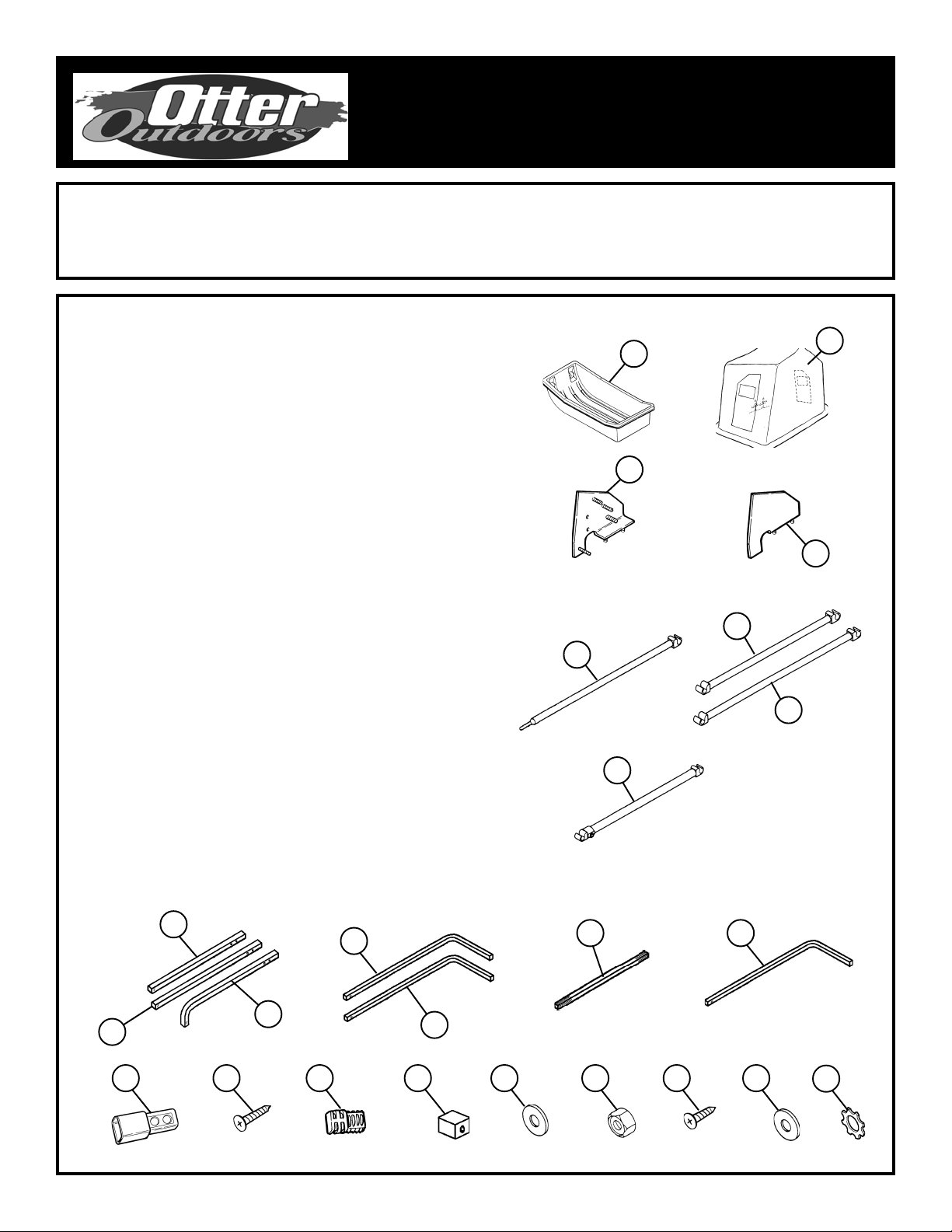
Parts Identification and Check List
MODEL NUMBERS:
Complete Pkg Pro XT 1200 Thermal Resort 200874
P ARTS LIST
Item # Qty Part # Description
1 1 200821 Sled - Black
2 1 200870 Tent-XT 1200 Thermal Resort
3 1 80172 Frame Bracket “A”
4 1 80171 Frame Bracket “B”
5 2 80548 Back Wind Support Bar - 49”
6 2 80546 Center Wind Support Bar - 37 5/8”
7 2 80547 Center Wind Support Bar - 49”
8 2 80549 Adjustable Front Wind Support Bar
9 2 80540 Main Frame Extension Bar - 34”
10 2 80541 Main Frame Extension Bar - 35 1/4”
1 1 4 80542 Main Frame Extension Bar - 29”
12 4 80544 Outer Main Frame Bar - 36 3/4”
13 2 80543 Outer Main Frame Bar - 32 5/8”
14 4 80545 Middle Main Frame Bar - 61 3/4”
15 2 80550 Outer Main Frame Bar - 32”
16 8 200384 Sleeve
17 16 400641 Self Tapping Screw #8 x 3/4”
18 8 200197 Black Plug
19 8 200195 Black End Cap
20 4 200615 5/16 Washer
21 12 400648 1/4 Nylon Hex Lock Nut
22 12 200942 3/8” Self Tapping Screw
23 16 200941 Plastic Protector
24 16 200943 Star Washer
1
2
3
4
6
5
7
8
Front
10
16
11
Back &
Center
9
Bottom
Front &
12
Bottom
13
Back
18 19 20 2117
Page 1
14
All
22
Center
15
23
Instructions - 70765
24

T ools Required:
7/16 Box End W rench 3/8 Bit
7/16 Socket and Ratchet 5/16 Bit
Drill
1. Layout all parts.
2. Position sled (Item 1) as shown
in Diagram 1, with curved front
to your left. Using front drilling
pattern (on back page) mark
two holes for the front frame
bracket with a sharp object.
Using rear drilling pattern (on
back page), repeat this step for
the rear frame bracket.
3. Drill the 4 marked holes using a
5/16 bit.
4. Drill the 3/8 in. hole in center of
lip approximately 16 inches from
bend in sled. The back wind
support bar (Item 5) is to be
propped here.
Diagram 1
16 in.
3/8 in.
Hole
1
Place front and rear drilling
patterns in these corners.
5. Bolt frame brackets (Item 3 and Item 4) to sled using holes predrilled in Step 3.
Use appropriate fasteners shown in Diagram 2.
Diagram 2
3
20
21
Item 20- 5/16 Washer
Item 21- 1/4 Nylon Hex Lock Nut
4
Page 2
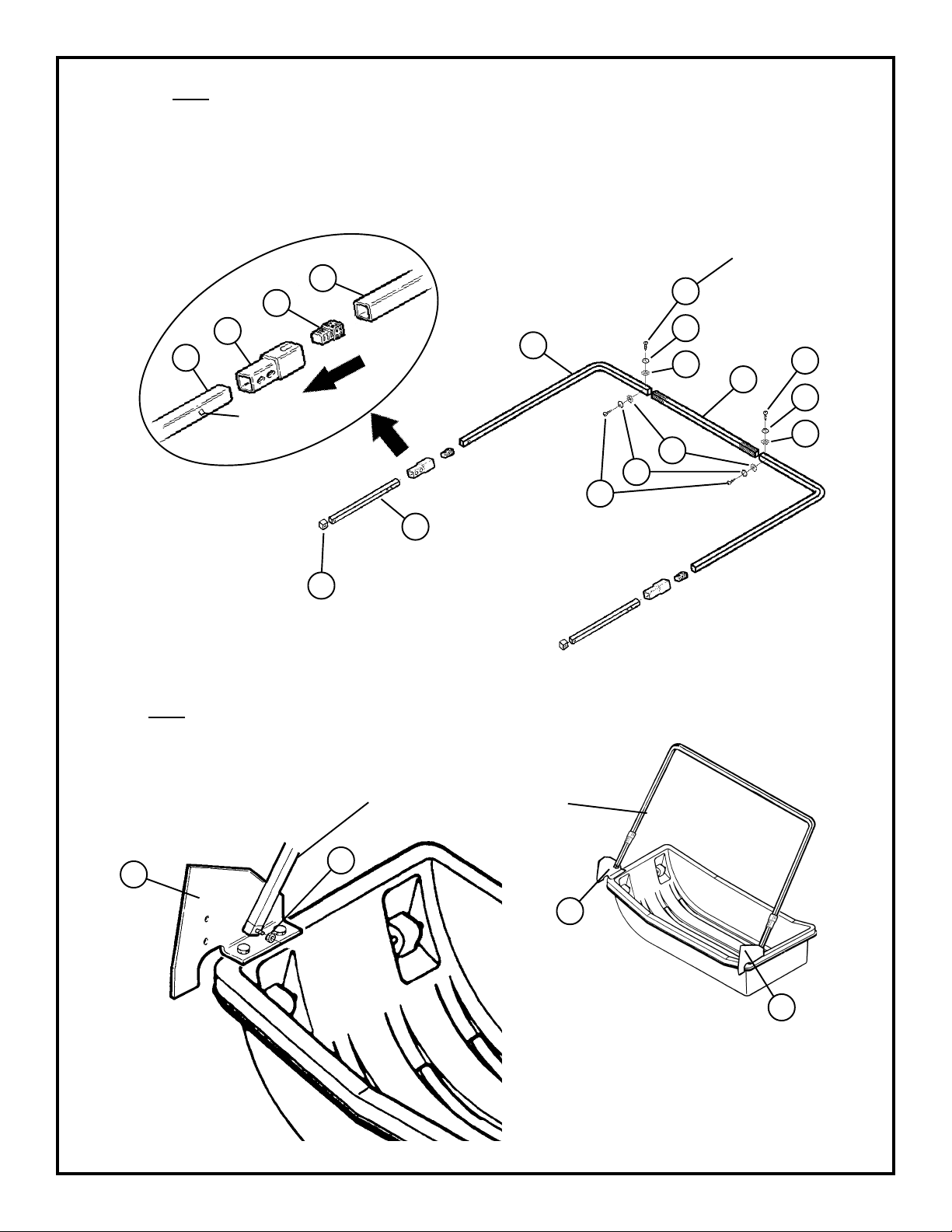
6. Assemble Back Main Frame Bar: Insert the outer main frame bar (Item 13) into the middle main frame bar
(Item 14). Fasten with self-tapping screw (Item 17), plastic protector (Item 23), and star washer (Item 24). Slide
the sleeve (Item 16) over the main frame extension bar (Item 11). (Line up holes with button lock, press lock
in as you slide over the bar). Insert the black plug (Item 18) into the main frame extension bar (Item 11). Insert
outer main frame bar (Item 13) into sleeve (Item 16). Cover end of main frame extension bar (Item 11) with black
end cap (Item 19). Ref. Diagram 3.
Diagram 3
Important: Do
not overtighten to
prevent stripping
of threads.
17
14
23
24
11
16
Button lock
should face
inward
18
13
17
23
13
24
24
23
17
Note: Use a light oil
11
such as WD-40 to
lubricate the poles to help
them slide easier. W ipe
19
off any excess. Silicone
may be substituted but is
not as effective.
7. Attach Back main frame assembly (Assembled in Step 6) onto frame brackets (Item 3 and 4). Secure with 1/4
nylon hex lock nut (Item 21). Ref. Diagram 4.
Diagram 4
Back Main Frame Assembly
3
21
3
Page 3
4
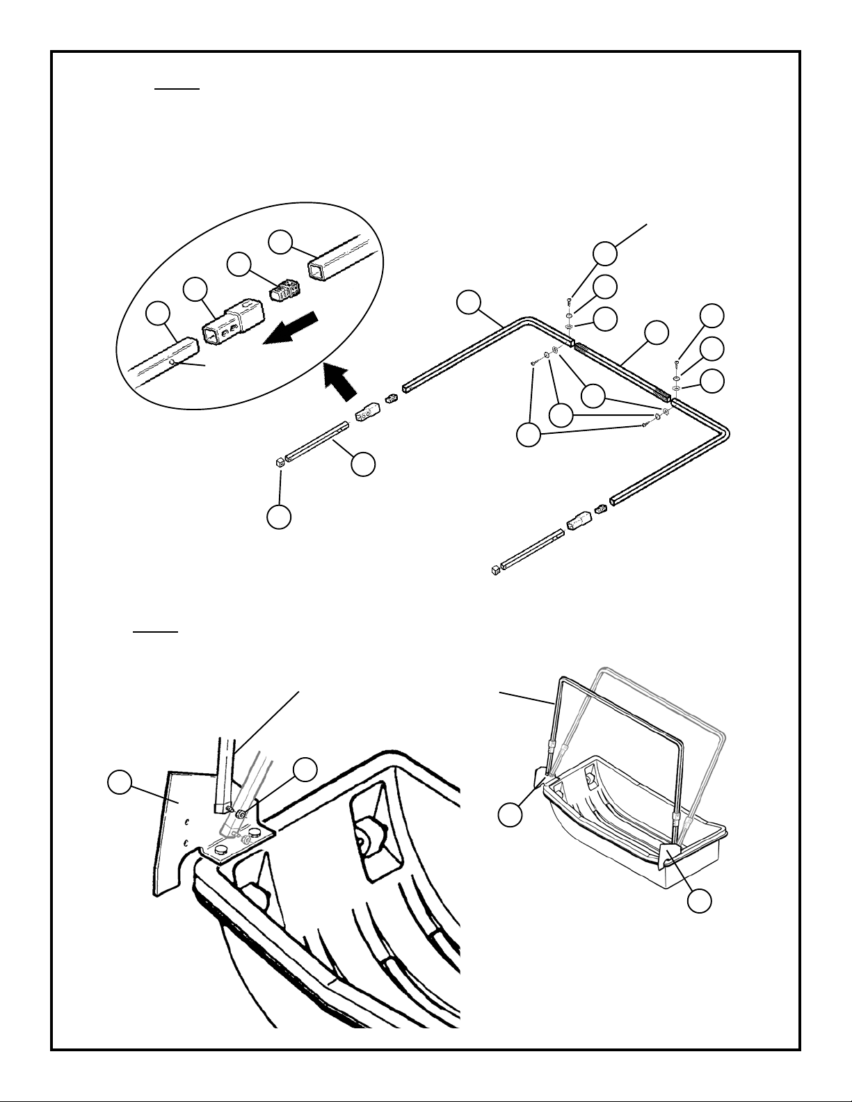
6. Assemble Center Main Frame Bar: Insert the outer main frame bar (Item 15) into the middle main frame bar
(Item 14). Fasten with self-tapping screw (Item 17), plastic protector (Item 23), and star washer (Item 24). Slide
the sleeve (Item 16) over the main frame extension bar (Item 11). (Line up holes with button lock, press lock
in as you slide over the bar). Insert the black plug (Item 18) into the main frame extension bar (Item 11). Insert
outer main frame bar (Item 15) into sleeve (Item 16). Cover end of main frame extension bar (Item 11) with black
end cap (Item 19). Ref. Diagram 3A.
Diagram 3A
Important: Do
not overtighten to
prevent stripping
of threads.
17
14
23
24
11
16
Button lock
should face
inward
18
15
17
23
15
24
24
23
17
Note: Use a light oil
11
such as WD-40 to
lubricate the poles to help
them slide easier. W ipe
19
off any excess. Silicone
may be substituted but is
not as effective.
7. Attach Center main frame assembly (Assembled in Step 6) onto frame brackets (Item 3 and 4). Secure with 1/4
nylon hex lock nut (Item 21). Ref. Diagram 4A.
Diagram 4A
3
Center Main Frame Assembly
21
3
Page 4
4
 Loading...