

Otterbine/Barebo Sunburst, Rocket, Phoenix, Gemini, Tri-Star Owner's Manual
...
Water Works
With Otterbine
1, 2, 3 & 5 Horsepower Surface Spray
CONCEPT
3
Owner's Manual
A Guide to More Dependable
Water Quality Management
With Otterbine Barebo Inc.'s
Aerating Fountain


Welcome Aboard!
Welcome to the growing family of people who depend on aerat ing fountains for better water quality control
and aesthetic improvement. Otterbine Barebo, Inc. moves its aerating fountain line into the next century
with a revolutionary platform. This design offers an industry first five-year warranty with virtually no
maintenance, reduced float visibility, and interchangeable spray patterns. All Otterbine products are safety
tested and approved by ETL, ETL-C and CE
CONTENTS
Safety Instructions ..................................................................................... 4
Aerator Equipment ..................................................................................... 5
Electrical/PCC Installation ......................................................................... 5-6
PCC Components ............................................................................ 6
Unit Assembly ............................................................................................ 7-8
Physical Installation ................................................................................... 9
Mooring ............................................................................................ 9
Anchoring ........................................................................................ 9
System Startup .......................................................................................... 10-11
Disconnect Switch ........................................................................... 10
Manual-Off-Auto Switch ................................................................... 10
GFCI ................................................................................................ 10
Timer Operation ............................................................................... 11
Maintenance .............................................................................................. 11
Winterization .............................................................................................. 11
Sunburst Pump Chamber .......................................................................... 12
Gemini Pump Chamber ............................................................................. 13
Saturn Pump Chamber .............................................................................. 14
Rocket Pump Chamber ............................................................................. 15
Phoenix Pump Chamber ........................................................................... 16
Tri-Star Pump Chamber ............................................................................ 17
Constellation Pump Chamber .................................................................... 18
Comet Pump Chamber .............................................................................. 19
Genesis Pump Chamber ........................................................................... 20
Equinox Pump Chamber ........................................................................... 21
Omega Pump Chamber ............................................................................. 22
Otterbine Warranty .................................................................................... 23
Water Quality Specialists
Barebo, Inc. is a team of scientists, engineers, and crafts persons who specialize in efforts to improve
water quality. Otterbine aerating fountains are built at Barebo, Inc.'s 25,000 square foot factory in
Emmaus, Pennsylvania.
The Concept 3 line of Otterbine aerators, made of stainless steel and high tech engineering plastics,
reflects the results of aerator research and development programs that started in 1956, p lus the
experience gained through thousands of installations on commercial fish farms, golf courses, parks, and
architectural applications.
75-0073 Revision 08 Concept 3 Owner’s Manual

SAFETY INSTRUCTIONS
ALL ELECTRICAL WORK MUST BE PERFORMED BY A QUALIFIED LICENSED ELECTRICIAN AND CO NFORM
WITH ALL APPLICABLE ELECTRICAL SAFETY CODES
Tous travaux électriques doivent être effectués par un électricien professionnel qualifié et conforme à tous les codes
applicables sécurité électrique
ALWAYS SWITCH OFF/DISCONNECT ALL EQUIPMENT IN THE WATER BEFORE SERVICING OR PERFORMING
ANY MAINTENANCE
Toujours éteindre l'équipement dans l'eau avant entretien ou de tout entretien
DO NOT OPERATE THE FOUNTAIN WHEN PEOPLE ARE IN THE WATER
Ne pas utiliser la fontaine quand les gens sont dans l’eau
CAUTION: KEEP HANDS CLEAR OF THE IMPELLER WHEN OPERATING!
ATTENTION: Garder les mains loin la turbine lors de l’utilisation!
• Before entering, wading in or swimming in the water in which Otterbine Aerators or Fountains are installed, make sure
they are PHYSICALLY disconnected from their electrical power sources.
• Aerators located in or near garden ponds and similar locations must be equipped with Ground Fault Circuit Interrupter.
• The permissible temperature range for this equipment is -12o to 40o C/10o to 104o F.
• It is possible for the water to become slightly polluted in the rare case that an oil leak occurs.
• If the power cord is damaged, it must be replaced by a special cord or assembly available from Otterbine/ Barebo, Inc.
or an authorized Otterbine/Barebo, Inc. sales and service center.
• Avant d'entrer, pataugeant dans ou en nageant dans l'eau dans laquelle Aérateurs Otterbine ou fontaines sont
installées, assurez-vous qu'ils sont physiquement déconnectés de leur source d'alimentation électrique.
• Aérateurs situés dans ou à proximité des bassins de jardin et des emplacements similaires doivent être équipés de
disjoncteur.
• La plage de température admissible pour cet appareil est-12 o à 40 oC/10 o à 104 oF aux.
• Il est possible pour que l'eau devient légèrement polluées dans les rares cas où une fuite d'huile se produit.
WARNINGS

• Si le cordon d'alimentation est endommagé, il doit être remplacé par un cordon spécial ou de montage d isponible à
p
partir Otterbine / Barebo, Inc ou une autorisation Otterbine / Barebo, les ventes Inc et centre de service.
INSPECT AERATOR EQUIPMENT
Immediately report any shipping damage to the carrier that delivered your aerator.
Inspect your aerator and verify the following:
Unit - Check the nameplate located on the housing of the aerator unit to make sure you have received the correct
horsepower and voltage aerator.
Power Control Center - Verify the PCC is compatible with the aerator unit horsepower and voltage. Refer to the electrical
specifications on the nameplate located inside on the door of the PCC.
Power Cable Assembly - Verify the correct cable gauge and length.
For proper warranty consideration return your Otterbine warranty registration card.
ELECTRICAL/PCC INSTALLATION
ELECTRICAL INSTALLATION MUST BE PERFORMED BY A QUALIFIED LICENSED ELECTRICIAN AND CONFO RM
TO ALL APPLICABLE LOCAL AND NATIONAL CODES
DISCONNECT EQUIPMENT FROM ELECTRICAL SUPPLY BEFORE SERVICING OR PERFORMING MAINTENANCE
Use Only OTTERBINE power cord. Do not splice or repair the cord, replacement is necessary if damage occurs.
The standard Power Control Center includes a fiberglass NEMA 4X enclosu re with twenty-four hour timer control in the
auto setting or manual control of the aerator unit, the required motor short circuit, ground fault and overcurrent protection,
surge protection, and personnel GFCI protection (except 460V 60Hz. applications).
Protection Device) is an optional accessory to provide 5, 10 or 30 mA ground fault protection.
Caution: GFCI Protection is required. If GFCI protection is not used, serious or FATAL electrical shock may
occur.
Attention: GFCI/RCD de protection est nécessaire. Graves ou mortelles choc électrique peut se produire s'il n'est
pas utilisé.
A. Feeder
1. Proper feeder circuit protection in accordance with all applicable local and national codes must be provided to the
power control center.
2. Be certain to properly size feeder conductors to allow for no more than 5% voltage drop for the entire circuit from the
feeder source to the aerator unit. Failure to do so may damage the aerator and void product warranty.
60Hz. Electrical S
HP Volts Phase Full Load Amps
1 115 1 15.5
1 208/230 1 8.3/7.5
2 208/230 1 13.7/12.4
3 208/230 1 15.5/14
3 208/230 3 9.7/8.6
3 380 3 4.6
3 460 3 4.3
5 230 Only 1 23
5 208/230 3 15.1/13.4
5 380 3 7.6
5 460 3 7.2
5 575 3 5.5
ecifications
B. PCC Location
1. The power control center should be mounted where easily visible from the shoreline where the aerator is located.
Important: The power control center shall not be accessible from the water.
Important: Le Centre de Contrôle de la puissance ne doit pas être accessible à partir de l'eau
On 460V units EPD (Equipment
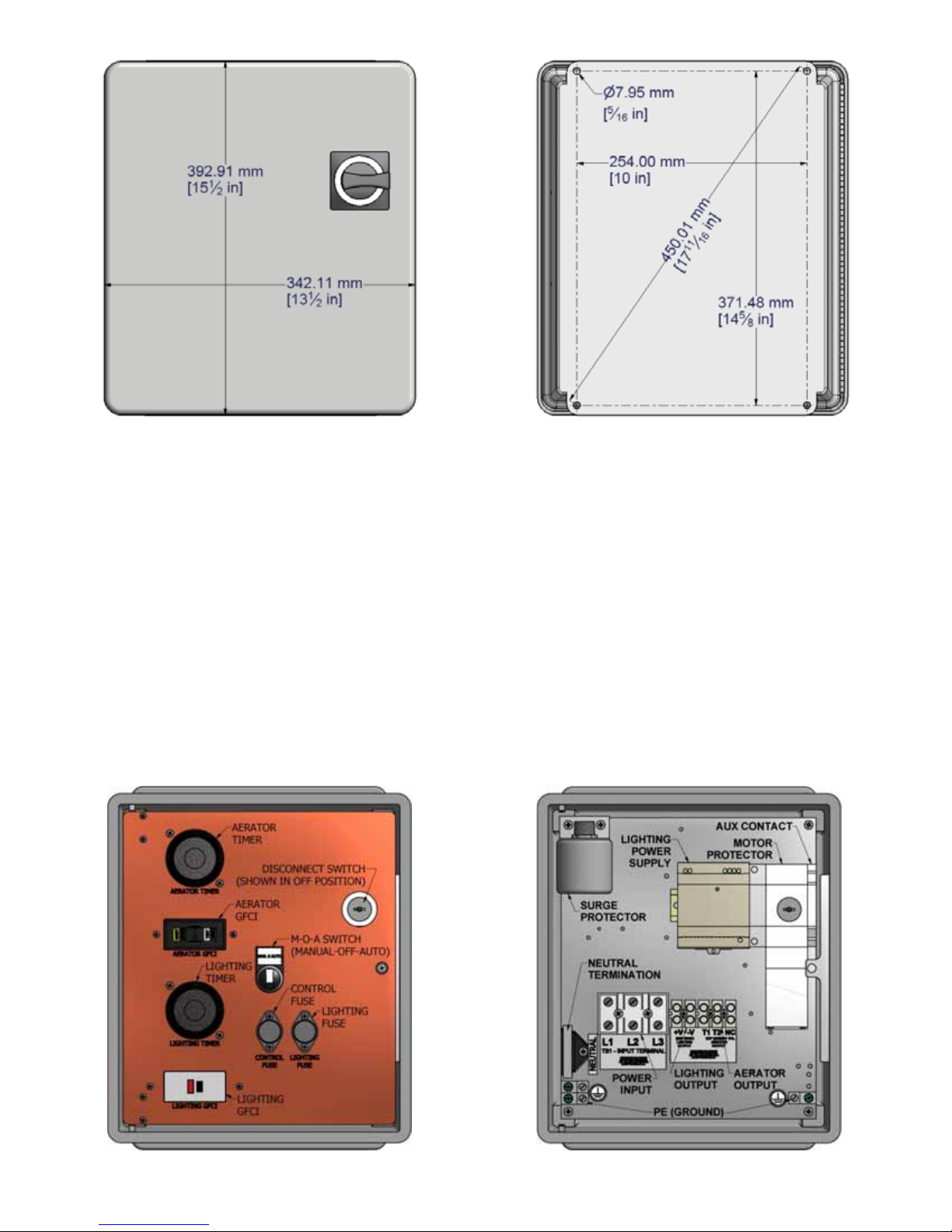
OVERALL DIMENSION MOUNTING HOLE LAYOUT
C. PCC Mounting
1. To prevent damage to the enclosure mount the enclosure using all four (4) mounting holes.
2. Whenever possible do not mount the PCC in direct sun light.
D. PCC Cables & Connections
1. Only Otterbine Barebo, Inc. factory approved power cord is to be used from the PCC to the aeration unit with no
junction boxes or splices. Only use power cord gauges and lengths spe cified b y Otterbine at the time of cable purchase.
(Contact your Otterbine Distributor for proper cable sizing)
2. It is recommended that all exposed cable between the PCC and the shoreline be installed in non-metallic conduit. It is
important that aerator and lighting cables be installed in individual conduits to avoid induced interference betwee n cables
which causes random GFCI tripping.
3. Always use strain relief cord connectors to attach the Otterbine cable to the PCC.
4. Cables and conduits must only enter into the bottom of the PCC.
5. Factory connections may loosen during shipping. Verify tightness of all screw terminal connections before energizing.
6. Power input and output wiring connections are accessed from the bottom of the enclosure. The terminal blocks for the
cable connections are located behind the hinged swing panel. Loosen the captive screw on the right center of the swing
panel for access.
Terminal Torque Values: Input – 45 in/lb. Maximum, Output – 30 in/lb. Maximum
SWING PANEL VIEW SUB-PANEL VIEW
UNIT ASSEMBLY
READ THE INSTRUCTIONS: Improper assembly may result in damage to the unit.
NOTES:
*Genesis Pump Chamber; The Float MUST be mounted before the Genesis Throat Assembly (Shown on page 20).
(The unit will be received with the pumping chamber already mounted)
*5HP "Open Throat" Units (Sunburst, Gemini, Saturn); If applicable, the Supplemental Float must be mounted to
the Main Float before installing on Unit (See Below).
A. Supplemental Float Assembly
*If the Supplemental Float is already mounted to the Main Float, continue with main float assembly below.
1. Place Main Float top face down.
2. Place the Supplemental Float on the Main Float as shown in the photo below.
3. Ty-Rap the floats together in four places (1 in each pocket).
4. Continue mounting Main Float.
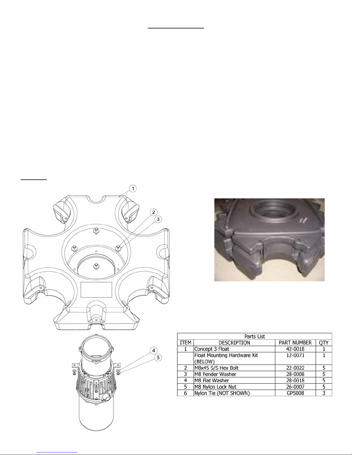
B. Main Float Assembly
1. Stand the unit upright and place the float onto it so the holes in the float line up with the holes in the mounting brackets.
2. Place a fender washer onto a hex bolt and insert into one of the four holes in the float making sure it also goes through
the hole in the steel mounting bracket on the unit. Repeat this for the three remaining holes.
3. Place a flat washer and a nylon locknut onto each of the four hex bolts. Tighten each nylon locknut.
CAUTION: Do not over tighten lock nuts, damage may occur to the float and/or pump chamber.
Fasten supplemental Float w/ Ty-Raps
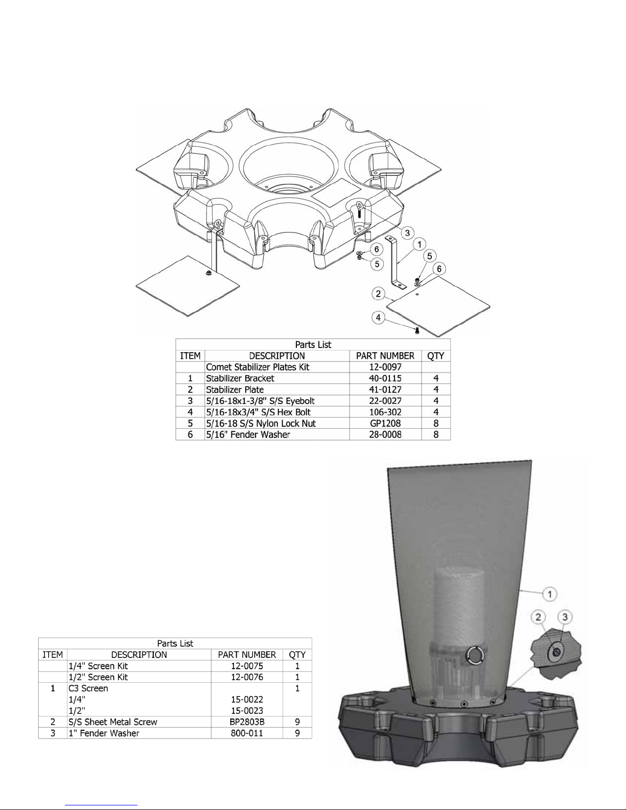
C. Mounting the Stabilizers (Comet Spray Pattern Only)
1. Mount each of the four stabilizer plates to the top side of a bracket using a hex bolt, a fender washer, and a nylon
locknut as shown below.
2. Mount each of the four stabilizer plate assemblies from Step C1 to the top side of an outer hole in the float using an
eyebolt, a fender washer, and a nylon locknut as shown. Do not over tighten. Damage may occur to the float.
D. Screen Installation
Debris Screens help to prevent clogging of the aerator and
are available for all Otterbine aerators.
1. Place the unit upside down on blocks so the pump chamber
does not get damaged.
2. Pull screen over motor unit until it reaches the lip on the
float.
3. Make sure the cable/s are running through the bushing in
the screen.
4. Fasten the screen to the lip on the float with the washers
and screws provided so they are evenly spaced around the
diameter.
 Loading...