

OT Systems FT010AB User Manual
FT010AB Series Installation & Operation Manual
Installation and Operation Manual
FT010AB Series
Digital Series
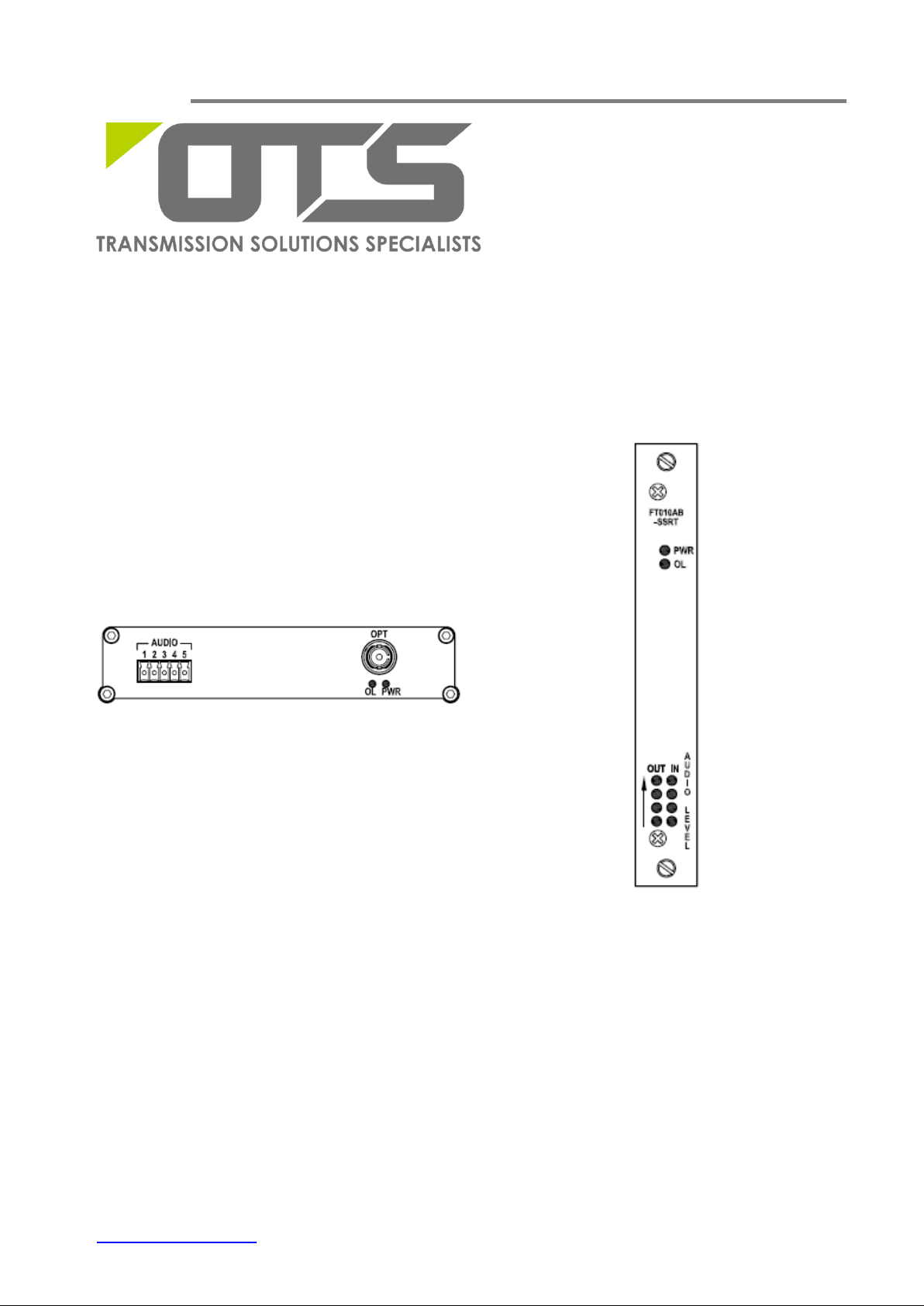
1-Ch Bi-directional Audio
Fiber Optic Converter
www.ot-systems.com 1
OT Systems Ltd., 2014
Rev 1.2

FT010AB Series Installation & Operation Manual
Standalone Units
Single-Mode Transmitters
FT010AB-SSTRSA
FT010AB-SSTRLSA
Single-Mode Receivers
FT010AB-SSRTSA
FT010AB-SSRTLSA
Multi-Mode Transmitter
FT010AB-SMTRSA
Multi-Mode Receiver
FT010AB-SMRTSA
Card Modules
Single-Mode Transmitters
FT010AB-SSTR
FT010AB-SSTRL
Single-Mode Receivers
FT010AB-SSRT
FT010AB-SSRTL
Multi-Mode Transmitter
FT010AB-SMTR
Multi-Mode Receiver
FT010AB-SMRT
Models covered in this manual
Remark:
If the optical connector is FC type, the suffix in the model number will be “-FXX”. Eg.
FT010AB-FSTR
www.ot-systems.com 2

FT010AB Series Installation & Operation Manual
Table of Contents
(1) SAFETY INSTRUCTIONS .................................................................................................................................. 4
(2) PRODUCT OVERVIEW .................................................................................................................................... 5
2.1 INTRODUCTION ..................................................................................................................................................... 5
2.2 MODELS SELECTION TABLE ...................................................................................................................................... 6
(3) INSTALLATION................................................................................................................................................ 7
3.1 GENERAL ............................................................................................................................................................. 7
3.2 STANDALONE UNIT INSTALLATION .............................................................................................................................. 7
3.3 CARD MODULE INSTALLATION................................................................................................................................... 8
(4) CABLE CONNECTIONS & SETUP PROCEDURES ................................................................................................ 8
4.1 SYSTEM CABLE CONNECTIONS ................................................................................................................................. 8
4.2 AUDIO PORT ASSIGNMENT AND PIN CONNECTIONS ..................................................................................................... 10
4.3 GROUND CONNECTION ......................................................................................................................................... 11
(5) OPERATIONAL GUIDES ................................................................................................................................. 12
5.1 FT010AB SERIES TRANSMITTER ............................................................................................................................ 12
5.2 FT010AB SERIES RECEIVER .................................................................................................................................. 12
(6) SPECIFICATIONS ........................................................................................................................................... 13
(7) DRAWINGS .................................................................................................................................................. 14
(8) WARRANTY INFORMATION ......................................................................................................................... 14
(9) CONTACT INFORMATION ............................................................................................................................. 15
www.ot-systems.com 3

FT010AB Series Installation & Operation Manual
(1) Safety Instructions
Please be familiar with all information in this manual prior to installation and
operation.
Note 1: The products described contain a Class 1 laser or LED fiber optic emitter. The following
safety precautions apply.
Warning: Do not disconnect the fiber optic connector while the unit is powered up.
Exposure to Class I invisible optical radiation is possible when the internal fiber optic
connector is disconnected while the unit is powered up.
Caution: Any access to the controls, adjustments, or performing operations, which are
other than those specified may result in hazardous radiation exposure. Permanent eye
damage or other bodily injuries may be resulted from such exposure even for only
seconds.
Note 2: This assembly contains parts sensitive to damage by electrostatic discharge (ESD). ESD
precautionary procedures should be applied in the course of touching, removing or inserting parts
or assemblies.
www.ot-systems.com 4

FT010AB Series Installation & Operation Manual
(2) Product Overview
2.1 Introduction
The FT010AB Series products comprise of either single-mode or multi-mode fiber optic
transmitters and receivers for the optical transmission of ONE bi-directional (Tx ↔ Rx) audio
signal on one fiber. The products work at wavelengths of 1310nm and 1550nm with either a
9/125um or 62.5/125um fiber for single-mode or multi-mode transmission respectively.
A 24-bit digital PCM transmission scheme is employed for analogue audio transmission.
Both balanced and unbalanced audio inputs and outputs are supported. Optical Wavelength
Division Multiplex (WDM) technique is also employed for simultaneous reverse audio signal
transmission.
For single-mode transmission, we also offer specifically designed products for long-haul
transmissions up to 60km. These models include the letter “L” in the suffix, e.g. FT010AB-SSTRL
for Tx, FT010AB-SSRTL for Rx, etc.
The FT010AB Series units are available as standalone units, which can be mounted
horizontally or vertically wall-mounted on any fixture. The standalone unit comes with an external
power supply FT-PA/12V, which can be powered by local 110/220V power.
The FT010AB Series units are also available as plug-in card modules installed in a 19”
rack-mount chassis. Each plug-in card occupies one slot in the rack-mount chassis. The rack
mount chassis has to be ordered separately, and comes with its own power supply for powering
the installed card modules.
www.ot-systems.com 5
 Loading...