

Page 1
1
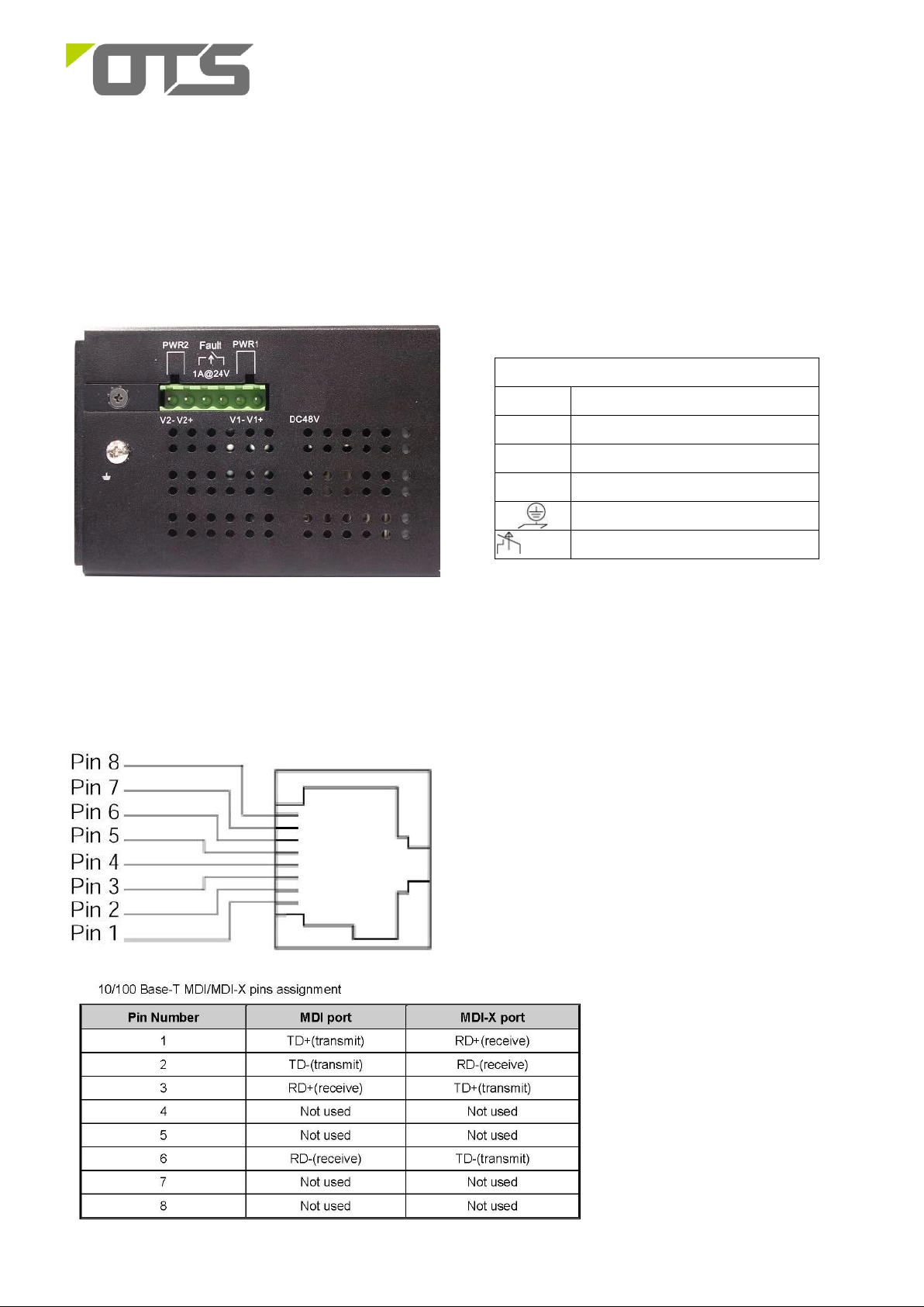
The Terminal Block
PWR1
Power Input 1 (12~48VDC)
GND
Power Ground
PWR2
Power Input 2 (12~48VDC)
GND
Power Ground
Earth Ground
FAULT
The relay opens if PWR1 or PWR2 fails (1A)
ET8242M-S-DR
Managed Industrial 8-port 10/100/1000Base-T/X SFP Combo + 4-port 1000Base SFP
Ethernet Switch
This quick start guide describes how to install and use the hardened Ethernet Switch. Capable of operating at temperature extremes of -10°C to
+60°C, this is the switch of choice for harsh environments constrained by space.
Physical Description
The Terminal Block and Power inputs
DC Terminal Block Power Inputs: There are two pairs of power inputs can be used to power up this Industrial Ethernet Switch. Redundant power
supplies function is supported. You only need to have one power input connected to run the Switch.
The 10/100/1000Base-TX and Mini-GBIC combo port
The 10/100Base-TX Connections
Page 2
2
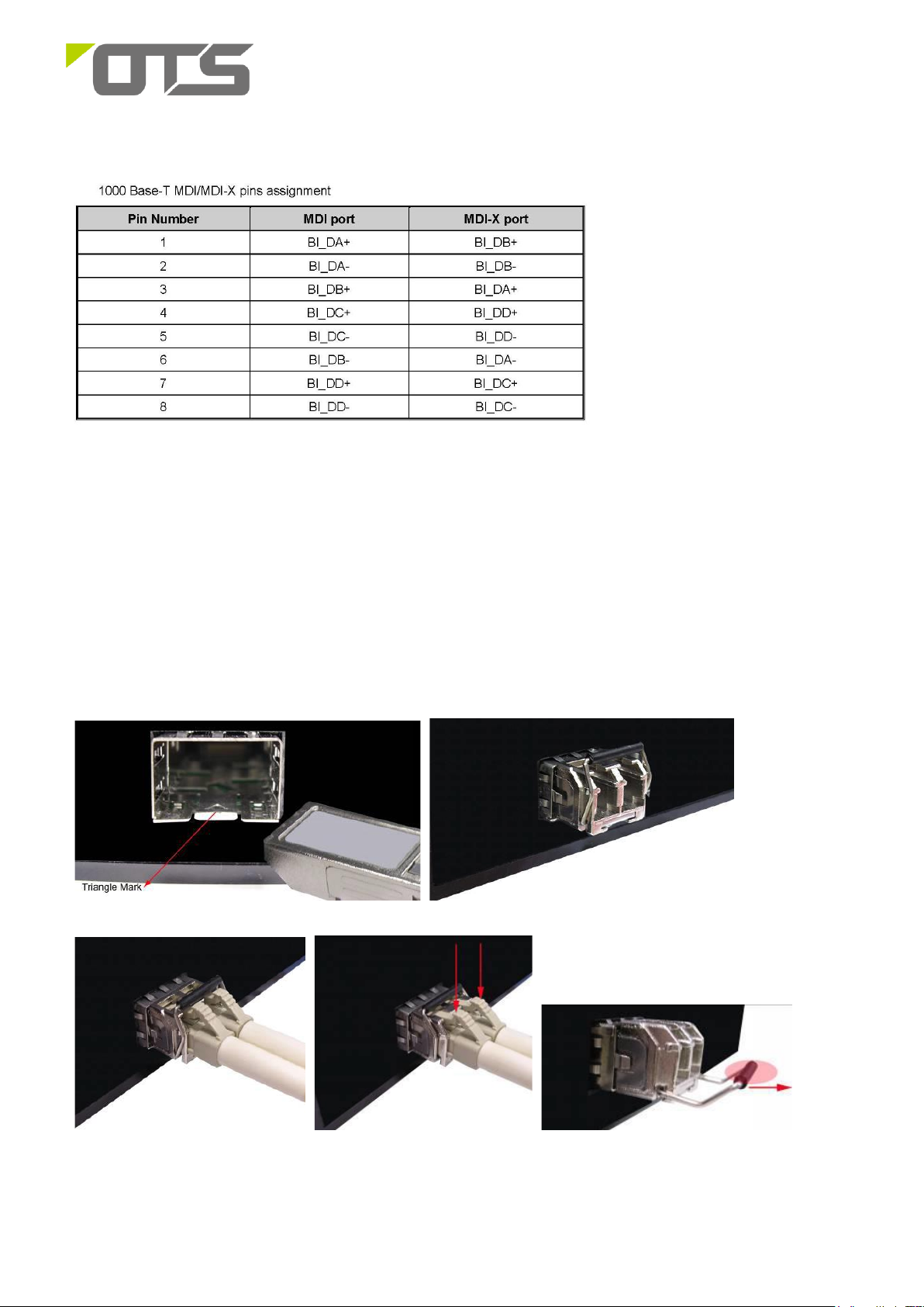
Mini-GBIC combo port:
8 auto-detect Giga port—UTP or fiber. The gigabit Ethernet ports are hared with the mini-GBIC ports. UTP (Gigabit Ethernet) ports can
operate in half/full-duplex modes and work at speeds of 10/100/1000Mbps that support auto-sensing technology to enable each port to detect
the connecting speed. The mini-GBIC port is a joint for a mini-GBIC (SFP) transceiver, the switch can be connected through fiber to another
one.
Use four twisted-pair, Category 5e or above cabling for RJ-45 port connection. The cable between the switch and the link partner (switch,
hub, workstation, etc.) must be less than 100 meters (328 ft.) long.
Use the mini-GBIC ports to uplink to another switch by inserting the mini-GBIC (SFP) transceiver.
ET8242M-S-DR
Managed Industrial 8-port 10/100/1000Base-T/X SFP Combo + 4-port 1000Base SFP
Ethernet Switch
Page 3
3
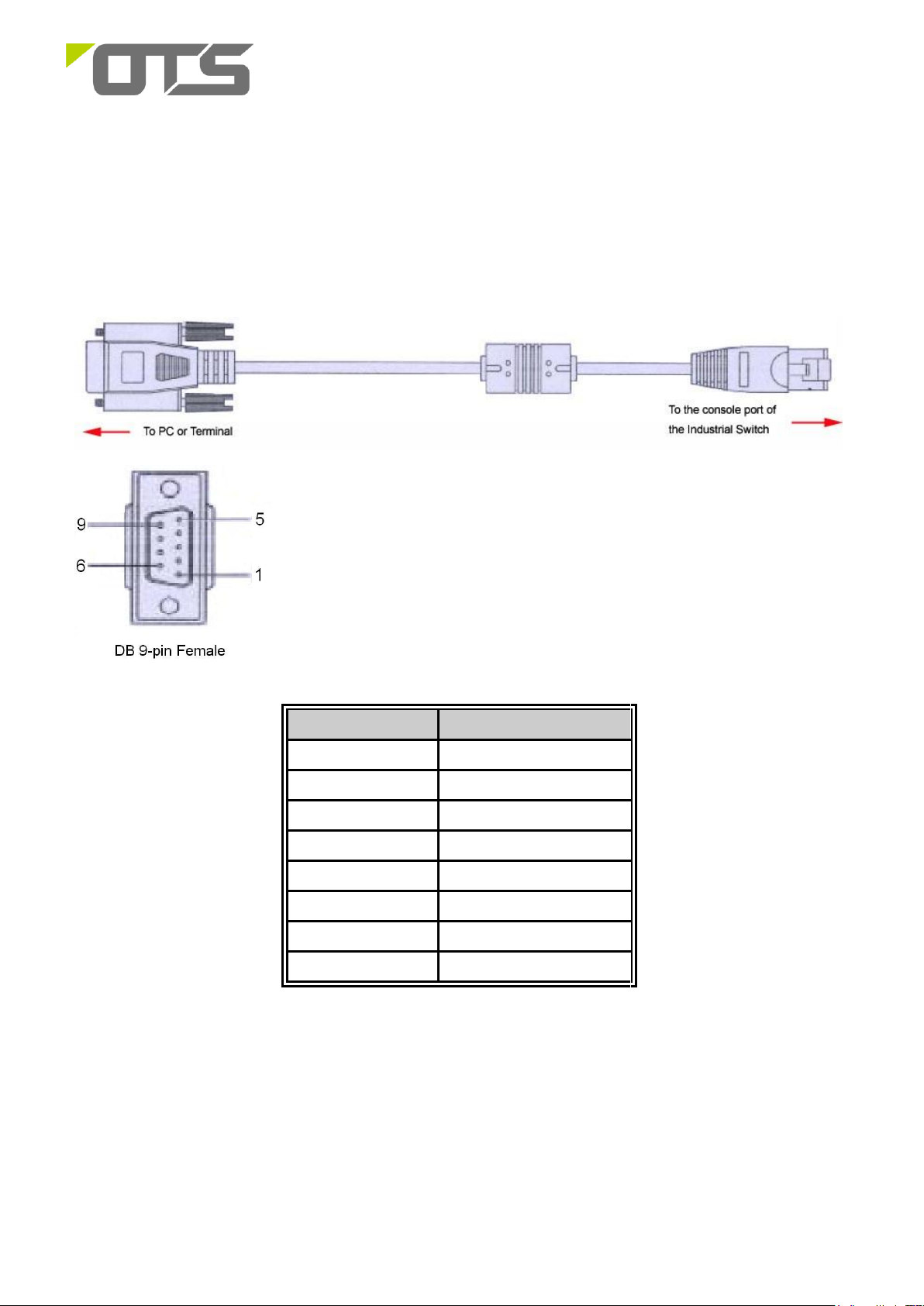
Connecting to the Console Port
The supplied cable which one end is RS-232 connector and the other end is RJ-45 connector. Attach the end of RS-232 connector to PC or
terminal and the other end of RJ-45 connector to the console port of the switch. The connected terminal or PC must support the terminal
emulation program.
Pin Assignment
DB9 Connector
RJ-45 Connector
NC
1 Orange/White
2
2 Orange
3
3 Green/White
NC
4 Blue
5
5 Blue/White
NC
6 Green
NC
7 Brown/White
NC
8 Brown
ET8242M-S-DR
Managed Industrial 8-port 10/100/1000Base-T/X SFP Combo + 4-port 1000Base SFP
Ethernet Switch
Page 4

4
Login in the Console Interface
When the connection between Switch and PC is ready, turn on the PC and run a terminal emulation program or Hyper Terminal and
configure its communication parameters to match the following default characteristics of the console port:
Baud Rate: 115200 bps
Data Bits: 8
Parity: none
Stop Bit: 1
Flow control: None
The settings of communication parameters
Having finished the parameter settings, click ‘OK’. When the blank screen shows up, press Enter key to have the
login prompt appears. Key in ‘root’ (default value) for both User name and Password (use Enter key to switch),
then press Enter and the Main Menu of console management appears. Please see below figure for login screen.
Console login interface
ET8242M-S-DR
Managed Industrial 8-port 10/100/1000Base-T/X SFP Combo + 4-port 1000Base SFP
Ethernet Switch
Page 5

5
Color
Status
Meaning
PWR
Green
On
The switch unit is power on
Off
No power
PWR1
Green
On
Power 1 is active
Off
Power 1 is inactive
PWR2
Green
On
Power 2 is active
Off
Power 2 is inactive
R.M.
Green
On
The industrial switch is the master of
X-Ring group
Off
The industrial switch is not a ring master
in X-Ring group
Ring
Green
On
Ring enabled
Slowly
blinking
Ring has only One link. (lack of one link to
build the ring.)
Fast
blinking
Ring work normally.
FAULT
Amber
On
Power or port failure
Off
No failure
Gigabit Ethernet ports
LNK/ACT
Green
Blinking
Data transmitted.
Full Duplex
Amber
On
Port works under full duplex.
Gigabit SFP ports
LNK/ACT
Green
On
The port is linking.
Blinks
Data transmitted.
Off
No device attached.
ET8242M-S-DR
Managed Industrial 8-port 10/100/1000Base-T/X SFP Combo + 4-port 1000Base SFP
Ethernet Switch
The Port Status LEDs, Wall Mounting Kit
LED Indicators
The diagnostic LEDs located on the front panel of the industrial switch provide real-time information of system and optional status. The following
table provides the description of the LED status and their meanings for the switch.
DIN-Rail Mounting
Page 6

6
ET8242M-S-DR
Managed Industrial 8-port 10/100/1000Base-T/X SFP Combo + 4-port 1000Base SFP
Ethernet Switch
The DIN-Rail is screwed on the industrial switch when out of factory. If the DIN-Rail is not screwed on the industrial switch, please see the
following pictures to screw the DIN-Rail on the switch. Follow the steps below to hang the industrial switch.
1. First, insert the top of DIN-Rail into the track.
2. Then, lightly push the DIN-Rail into the track.
3. Check if the DIN-Rail is tightened on the track or not.
4. To remove the industrial switch from the track, reverse steps above.
Wall Mount Plate Mounting
Page 7

7
ET8242M-S-DR
Managed Industrial 8-port 10/100/1000Base-T/X SFP Combo + 4-port 1000Base SFP
Ethernet Switch
Follow the steps below to mount the industrial switch with wall mount plate.
1. Remove the DIN-Rail from the industrial switch; loose the screws to remove the DIN-Rail.
2. Place the wall mount plate on the rear panel of the industrial switch.
3. Use the screws to screw the wall mount plate on the industrial switch.
4. Use the hook holes at the corners of the wall mount plate to hang the industrial switch on the wall.
5. To remove the wall mount plate, reverse steps above.
Functional Description
Meets IEC61000-6-2 EMC Generic Standard Immunity for industrial environment.
Page 8

8
ET8242M-S-DR
Managed Industrial 8-port 10/100/1000Base-T/X SFP Combo + 4-port 1000Base SFP
Ethernet Switch
Support 802.3/802.3u/802.3ab/802.3z/802.3x.
RJ45 ports Auto-negotiation: 10/100/1000Mbps, Full/half-duplex; Auto MDI/MDIX.
SFP (Mini-GBIC) combo port supports 100/1000 Dual Mode.
Support 8K MAC addresses. Provides 4 priority queues.
Alarms for power or ports failure by relay output, Carry capacity of 1A @ 24VDC.
Operating voltage and Max. current consumption: 1.84A @ 12VDC, 0.92A @ 24VDC. Power consumption: 22W Max.
Power Supply: Redundant DC Terminal Block power inputs, 12~48VDC on 6-pin terminal block.
Operating temperature ranges from -10°C to +60°C.
Supports Wall Mounting installation; Optional DIN-Rail mounting kit.
Assembly, Startup, and Dismantling
Wall Mounting Kit installation
Assembly: Securely fasten the wall-mount kits to the bottom of module by using the provided screws (6 pcs)
Mount the standalone unit onto a fixture, e.g. a plank, (either on the wall or on a flat surface) with at least 2 screws piercing
through the holes on the mounting frame to secure it in position.
Startup: Connect the supply voltage to start up the Industrial Ethernet Switches via the terminal block.
Dismantling: Locate and remove the securing screws. Usually, but not limited to, at least 2 screws.
DIN rail installation (Optional)
Assembly: Place the Media Converter on the DIN rail from above using the slot. Push the front of the Media Converter
toward the mounting surface until it audibly snaps into place.
Startup: Connect the supply voltage to start up the Industrial Ethernet Switches via the terminal block.
Dismantling: Pull out the lower edge and then remove the Industrial Ethernet Switches from the DIN rail.
Manual Earth Green manual is available in our website. www.ot-systems.com
 Loading...