


1
ET8122MPp-S-DR
Industrial Managed 8-port 10/100Base-TX (PoE+) + 2-port 10/100/1000Base-T/SFP Combo Ethernet Switch
This quick start guide describes how to install and use the 8-port 10/100Base-TX + 2 10/100/1000Base-T/S F P Combo Managed PoE Ethernet
o
Switch. This is designed to provide power to PoE driven devices. The switches operate in a temperature range of -10
PSE and external SFP work. It is suitable for use to build PoE network environment, and SFP slot designed to support a variety of SFP modules,
allowing the construction of Ethernet more flexible.
C to 60oC, supports PoE
Overview
ET8122MPp-S is a 8 ports 10/100Base-TX + 2 ports 10/100/1000Base-T/SFP Managed PoE Ethernet
Switch. The Switch provides the PoE+ function for kinds of Powered Devices to receive power as well as
data over the RJ-45 cable. SFP ports to support the use of SFP (Small Form-factor Pluggable)
transceiver module. User can chose different types of SFPs (1000M only). The Switch supports 1 or 2
core Single-mode or Multi-mode fiber. The product operates at temperatures ranging from -10
and
DIN-Rail installation.
General
o
C to 60oC
To ensure trouble free transportation and storage, all OT Sys tems products must be tho roughly inspected,
tested and properly packed before delivery. Check the product upon receipt for any visible damage which
may have been caused during shipment.
Package Content
8-port 10/100Base-TX (PoE+) + 2-port 10/100/1000Base-T/SFP Combo Managed Ethernet Switch x
1
Quick Start Guide x 1
V1.0
2
ET8122MPp-S-DR
Industrial Managed 8-port 10/100Base-TX (PoE+) + 2-port 10/100/1000Base-T/SFP Combo Ethernet Switch
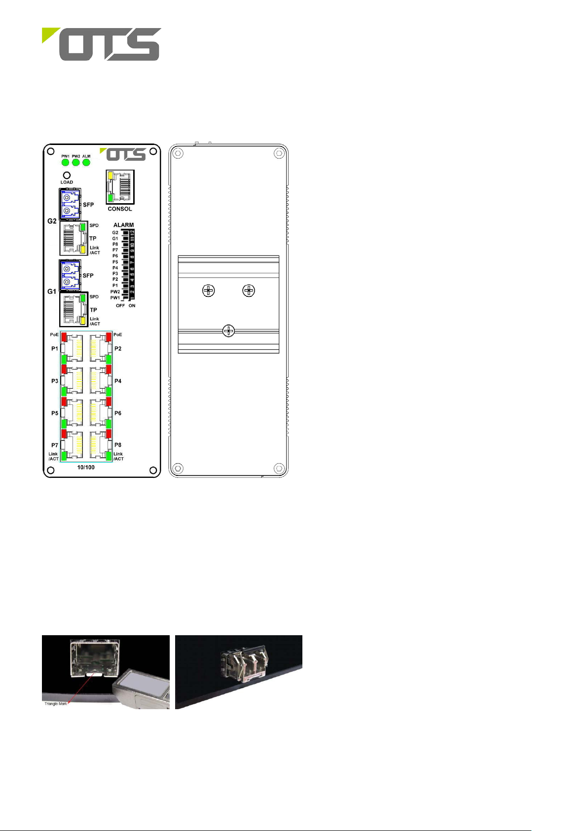
Physical Description
Front Panel Rear Panel
Installation
SFP Transceiver Module
You can select different S FP modules as required (Please refer to our SFP s e lec tion list for the
appropriate module).
To insert/remove the SFP, the procedures are as follows :
1. On the front panel, insert the SFP module into
the SFP port until it is securely locked.
V1.0
3
ET8122MPp-S-DR
Industrial Managed 8-port 10/100Base-TX (PoE+) + 2-port 10/100/1000Base-T/SFP Combo Ethernet Switch
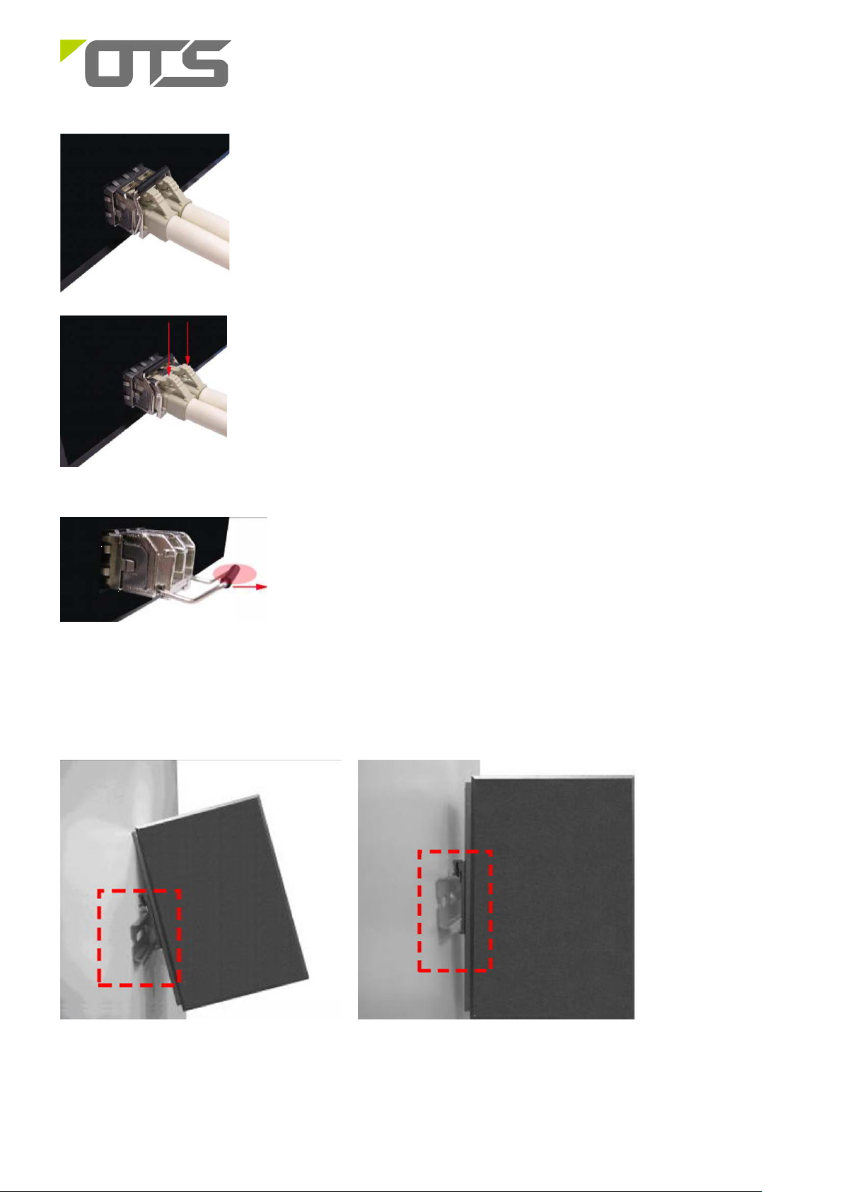
2. Connect the optical fiber (1/2 core) to the LC connector(s) of the SFP.
3. To re move the SFP modul e, press down the lock of the LC connector of the
optical fiber to pull out the fiber cable.
4. Pull down the SFP lever and hold its position. Pull out the SFP module
from the SFP port.
Din-rail Mounting
ET8122MPp-S can be installed on a DIN rail. Installation steps are as follows:
1. First, insert the top of DIN-Rail into the track.
2. Then, lightly push the DIN-Rail into the track.
3. Check if the DIN-Rail is tightened on the track or not.
4. To remove the industrial switch from the track, reverse steps above.
V1.0

4
DB9 Connector
RJ-45 Connector
ET8122MPp-S-DR
Industrial Managed 8-port 10/100Base-TX (PoE+) + 2-port 10/100/1000Base-T/SFP Combo Ethernet Switch
Setup
a) Connect the Ethernet port of the optical Ethernet switch to be used to a PC or network device with a
network cable.
b) Insert the appropriate SFP into the corresponding SFP port . Connect the fiber cable from the remote
device (media converter or switch) to the LC connector of the SFP.
c) After the device is powered on, th e PW R indicator will all be on. If the indicators are not on, check the
power supply connection.
d) After all cables are correctly connected, the indicators will be lit as per port status LEDs (page 8).
Connecting to the Console Port
The supplied cable which one end is RS-232 connector and the other end is RJ-45 connector. Attach the
end of RS-232 connector to PC or terminal and the other end of RJ-45 connector to the console port of
the switch. The connected terminal or PC must support the terminal emulation program.
Consol Pin Assignment
NC 1 Orange/White
2 2 Orange
3 3 Green/White
NC 4 Blue
5 5 Blue/White
NC 6 Green
NC 7 Brown/White
NC 8 Brown
V1.0

5
ET8122MPp-S-DR
Industrial Managed 8-port 10/100Base-TX (PoE+) + 2-port 10/100/1000Base-T/SFP Combo Ethernet Switch
Login in the Console Interface
When the connection between Switch and PC is ready, turn on the PC and run a terminal emulation
program or Hyper Terminal and configure its communication parameters to match the followi ng default
characteristics of the console port:
Baud Rate: 115200 bps
Data Bits: 8
Parity: none
Stop Bit: 1
Flow control: None
The settings of communication parameters
Having finished the parameter settings, click ‘OK’. When the blank screen shows up, press Enter key to
have the login prompt appears. Key in ‘ admin’ ( default value) for User name and ‘system’ for Password
(use Enter key to switch), then press Enter and the Main Menu of console management appears. Please
see below figure for login screen.
V1.0

6
ET8122MPp-S-DR
Industrial Managed 8-port 10/100Base-TX (PoE+) + 2-port 10/100/1000Base-T/SFP Combo Ethernet Switch
Web Configuration
Login the switch:
Specify the default IP address (192.168.2.1) of the switch in the web browser. A login window will be
shown as below:
Enter the factory default login ID: admin.
Enter the factory default password: system.
Then click on the “OK” button to log on to the swit ch.
V1.0

7
ET8122MPp-S-DR
Industrial Managed 8-port 10/100Base-TX (PoE+) + 2-port 10/100/1000Base-T/SFP Combo Ethernet Switch
Interface
Ethernet Port RJ-45 Pin Assignment
10/100Base-T Pins
Pin MDI MDIX MDI MDIX
1 TD+ RD+ TP0+ TP1+
2 TD- RD- TP0- TP13 RD+ TD+ TP1+ TP0+
4 Positive (VCC+) Positive (VCC+) TP2+ TP3+
5 Positive (VCC+) Positive (VCC+) TP2- TP36 RD- TD- TP1- TP07 Negative (VCC-) Negative (VCC-) TP3+ TP2+
8 Negative (VCC-) Negative (VCC-) TP3- TP2-
Power Connection
Pin
Description
Power Input GND
V1 - V1 + V2 - V2 +
+48~57V
GND
(DC)
+48~57V
(DC)
1000Base-T Pins
Cable Connection
Signal Type Cable Type Connector
Ethernet Cat. 5 or above RJ45
Optical SM/MM Optical fiber cable (depends on SFP) LC
Power supply 1 Power cable
Power supply 2 Power cable
ALM UTP
6-pin Terminal Block(Pin 1/2)
6-pin Terminal Block(Pin 5/6)
6-pin Terminal Block(Pin 3/4)
V1.0

8
ET8122MPp-S-DR
Industrial Managed 8-port 10/100Base-TX (PoE+) + 2-port 10/100/1000Base-T/SFP Combo Ethernet Switch
Cable Connection
Indicator Color Status Description
PW1 Green
PW2 Green
ALM Green ON
G1,G2
RJ45 Port
(P1-P8)
Dip Switch
PW1, PW2 Power 1 and Power2 failure alarm function on/off.
SPD Amber
LINK/ACT Green
PoE Amber
LINK/ACT Green
ON Powered on
ON Powered on
Power Failure or Port Down/fail
ON
OFF
ON A network device is connected
Blinking The connected device is transmitting or receiving data.
OFF No network device is connected
ON PoE is activated.
Blinking A Power Device (PD) is being detected.
OFF No device is connected or the connected device is not a PD.
ON A network device is connected
Blinking The connected device is transmitting or receiving data.
OFF No network device is connected
Operating at speed 1000M
No network device is connected or not operating at speed of 1000M
P1~P8 Each TP port Link failure alarm function on/off.
G1,G2 Each Giga port Link failure alarm function on/off.
Dimension drawing
V1.0

9
ET8122MPp-S-DR
Industrial Managed 8-port 10/100Base-TX (PoE+) + 2-port 10/100/1000Base-T/SFP Combo Ethernet Switch
Functi ona l Description
• 8 10/100Base-TX + 2 10/100/1000Base-T/SFP Combo
• Supports IEEE 802.3at PoE+(30W per port)
• RJ45 10/100Mbps Full/half-duplex, Auto-negotiation, Auto MDI/MDIX
• Combo RJ45 10/100/1000Mbps Full/half-duplex, Auto-negotiation, Auto MDI/MDIX
• Supports external SFP
• Supports 802.3x Flow Control
• Support 4K MAC address
• 2.75M bit frame buffer memory
•
Supports Relay output for Power and Port failure.
•
DIN-Rail installa t io n .
•
Redundant Power Inputs.
o
• -10
Manual Earth Green manual is available in our website. www.ot-systems.com
C to 60oC (14oF℉to 140oF) operating temperature range.
V1.0
 Loading...