

Page 1

ET2111 Series Installation & Operation Manual
Installation and Operation Manual
ET2111 Series
Network Switches Series
Unmanaged Industrial 2-port 10/100BASE-TX + 100BASE-FX
Ethernet Switch
OT Systems Ltd., 2014
Rev 1.1
www.ot-systems.com 1
Page 2

ET2111 Series Installation & Operation Manual
Fiber connector in SC
Multi-Mode (2-Fiber)
ET2111-A-SA
Single-Mode (2-Fiber)
ET2111-B-SA
Multi-Mode (1-Fiber)
ET2111-C-SA
ET2111-D-SA
Single-Mode (1-Fiber)
ET2111-E-SA
ET2111-F-SA
Fiber connector in ST
Multi-Mode (2-Fiber)
ET2111-G-SA
Single-Mode (2-Fiber)
ET2111-H-SA
Multi-Mode (1-Fiber)
ET2111-I-SA
ET2111-J-SA
Single-Mode (1-Fiber)
ET2111-K-SA
ET2111-L-SA
Fiber connector in SC
Multi-Mode (2-Fiber)
ET2111-A-CM
Single-Mode (2-Fiber)
ET2111-B-CM
Multi-Mode (1-Fiber)
ET2111-C-CM
ET2111-D-CM
Single-Mode (1-Fiber)
ET2111-E-CM
ET2111-F-CM
Fiber connector in ST
Multi-Mode (2-Fiber)
ET2111-G-CM
Single-Mode (2-Fiber)
ET2111-H-CM
Multi-Mode (1-Fiber)
ET2111-I-CM
ET2111-J-CM
Single-Mode (1-Fiber)
ET2111-K-CM
ET2111-L-CM
Models covered in this manual
Standalone units
Card Modules
www.ot-systems.com 2
Page 3

ET2111 Series Installation & Operation Manual
Table of Contents
TABLE OF CONTENTS............................................................................................................................................... 3
(1) SAFETY INSTRUCTIONS .................................................................................................................................. 4
(2) PRODUCT OVERVIEW .................................................................................................................................... 5
2.1 INTRODUCTION ..................................................................................................................................................... 5
2.2 PRODUCTS HIGHLIGHTS .......................................................................................................................................... 5
2.3 MODELS SELECTION TABLE ...................................................................................................................................... 6
(3) INSTALLATION................................................................................................................................................ 7
3.1 GENERAL ............................................................................................................................................................. 7
3.2 PACKAGE CONTENTS .............................................................................................................................................. 7
3.3 SELECTING A SITE FOR THE SWITCH ........................................................................................................................... 8
3.4 CONNECTING TO POWER ........................................................................................................................................ 8
DC Jack Power Input ......................................................................................................................................... 8
DC Power Input .................................................................................................................................................. 8
3.5 INSTALLATION ....................................................................................................................................................... 9
(4) CABLE CONNECTIONS & SETUP PROCEDURES .............................................................................................. 11
4.1 SYSTEM CABLE CONNECTIONS ................................................................................................................................ 11
4.2 CONNECTING TO YOUR NETWORK .......................................................................................................................... 12
4.2.1 The 10/100Base-TX Connector ....................................................................................................... 12
4.2.2 The 100Base-FX Connectors ........................................................................................................... 13
(5) OPERATIONAL GUIDES ................................................................................................................................. 14
5.1 LEDS STATUS...................................................................................................................................................... 14
5.2 SIGNAL AND POWER PORTS ................................................................................................................................... 14
(6) SPECIFICATIONS ........................................................................................................................................... 15
(7) DRAWINGS .................................................................................................................................................. 17
(8) WARRANTY INFORMATION ......................................................................................................................... 17
(9) CONTACT INFORMATION ............................................................................................................................. 18
APPENDIX A ............................................................................................................................................................ A
1. CONNECTOR PINOUTS ................................................................................................................................... A
www.ot-systems.com 3
Page 4

ET2111 Series Installation & Operation Manual
(1) Safety Instructions
Please be familiar with all information in this manual prior to installation and
operation.
Note 1: The products described contain a Class 1 laser or LED fiber optic emitter. The following
safety precautions apply.
Warning: Do not disconnect the fiber optic connector while the unit is powered up.
Exposure to Class I invisible optical radiation is possible when the internal fiber optic
connector is disconnected while the unit is powered up.
Caution: Any access to the controls, adjustments, or performing operations, which are
other than those specified, may result in hazardous radiation exposure. Permanent eye
damage or other bodily injuries may be resulted from such exposure even for only
seconds.
Note 2: This assembly contains parts sensitive to damage by electrostatic discharge (ESD). ESD
precautionary procedures should be applied in the course of touching, removing or inserting parts
or assemblies.
www.ot-systems.com 4
Page 5

ET2111 Series Installation & Operation Manual
(2) Product Overview
2.1 Introduction
OT Systems' ET2111 media converter offers an easy and affordable solution for network
managers to connect 10/100 Fast Ethernet from UTP to fiber optic cabling. The switch uses a
high performance auto-sensing exchange chip for full functionality of transfer and exchange,
guaranteeing the safety and stability of data transfer. The switches are Standalone Wall-mount
and can also operate in ET-C12 rack mount chassis, taking care of different installations.
2.2 Products Highlights
Basic Features
Converts 10/100Base-TX to 100Base-FX
Full/Half duplex, Auto-Negotiation
Singlemode or Multimode fiber operation
Single or Dual-core fiber with SC or ST connectors
Store and forward switching mechanism
MDI/MDI-X Auto-Crossover supported
Plug-and-Play
-20 °C to 60 °C (-4 °F to 140 °F) operating temperature
Wall-mount or operate in ET-C12 rack mount chassis.
www.ot-systems.com 5
Page 6

ET2111 Series Installation & Operation Manual
Models
Descriptions
Fiber Options
Wavelengths
Links
Budget
Max.
Distance
Installation
requirements
ET2111-A-SA
Multimode/2-fiber/SC
1310nm
14dB
2Km
Horizontally or
vertically
wall-mounted
Standalone
unit
1
ET2111-B-SA
Singlemode/2-fiber/SC
1310nm
21dB
20Km
ET2111-C-SA
Multimode/WDM 1-fiber/SC
TX:1310nm/RX1550nm
21dB
2Km
ET2111-D-SA
Multimode/WDM 1-fiber/SC
TX:1550nm/RX1310nm
21dB
2Km
ET2111-E-SA
Singlemode/WDM 1-fiber/SC
TX:1310nm/RX1550nm
19dB
20Km
ET2111-F-SA
Singlemode/WDM 1-fiber/SC
TX:1550nm/RX1310nm
19dB
20Km
ET2111-G-SA
Multimode/2-fiber/ST
1310nm
14dB
2Km
ET2111-H-SA
Singlemode/2-fiber/ST
1310nm
21dB
20Km
ET2111-I-SA
Multimode/WDM 1-fiber/ST
TX:1310nm/RX1550nm
21dB
2Km
ET2111-J-SA
Multimode/WDM 1-fiber/ST
TX:1550nm/RX1310nm
21dB
2Km
ET2111-K-SA
Singlemode/WDM 1-fiber/ST
TX:1310nm/RX1550nm
19dB
20Km
ET2111-L-SA
Singlemode/WDM 1-fiber/ST
TX:1550nm/RX1310nm
19dB
20Km
ET2111-A-CM
Multimode/2-fiber/SC
1310nm
14dB
2Km
Housed in
ET-C12
chassis
2
ET2111-B-CM
Singlemode/2-fiber/SC
1310nm
21dB
20Km
ET2111-C-CM
Multimode/WDM 1-fiber/SC
TX:1310nm/RX1550nm
21dB
2Km
ET2111-D-CM
Multimode/WDM 1-fiber/SC
TX:1550nm/RX1310nm
21dB
2Km
ET2111-E-CM
Singlemode/WDM 1-fiber/SC
TX:1310nm/RX1550nm
19dB
20Km
ET2111-F-CM
Singlemode/WDM 1-fiber/SC
TX:1550nm/RX1310nm
19dB
20Km
ET2111-G-CM
Multimode/2-fiber/ST
1310nm
14dB
2Km
ET2111-H-CM
Singlemode/2-fiber/ST
1310nm
21dB
20Km
ET2111-I-CM
Multimode/WDM 1-fiber/ST
TX:1310nm/RX1550nm
21dB
2Km
ET2111-J-CM
Multimode/WDM 1-fiber/ST
TX:1550nm/RX1310nm
21dB
2Km
ET2111-K-CM
Singlemode/WDM 1-fiber/ST
TX:1310nm/RX1550nm
19dB
20Km
ET2111-L-CM
Singlemode/WDM 1-fiber/ST
TX:1550nm/RX1310nm
19dB
20Km
2.3 Models selection table
1
ET-PA/12V 1.25A 12VDC power adapter works under 100-240VAC, 50/60Hz power supply; DC Jack(US, European, UK or
Australian power plug available)
2
Refer to ET-C12 for specifications.
www.ot-systems.com 6
Page 7
ET2111 Series Installation & Operation Manual
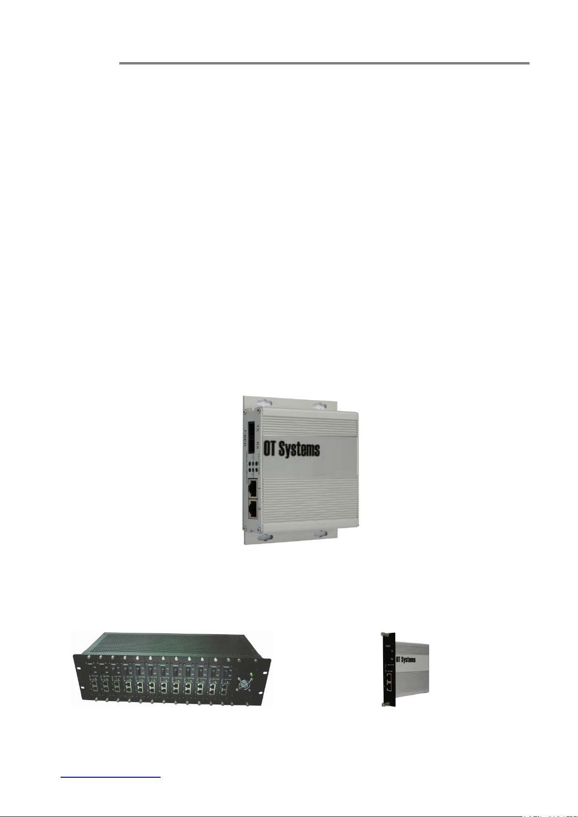
Fig. 3.2 (a) ET-C12
Fig. 3.2 (b) Card module
(3) Installation
3.1 General
All OT Systems products are thoroughly inspected, tested and securely packaged before
delivery to ensure a stable, intact and trouble-free service. Please check the equipment upon
receipt for any visible damage which may have been caused during shipping.
3.2 Package Contents
When you unpack the product package, you shall find the items listed below. Please inspect
the contents, and report any apparent damage or missing items immediately to your authorized
reseller.
Ethernet Switch
Quick Installation Guide
External power adapter & Power Cord (for Standalone Wall-mount type)
The Standalone type ET2111 Series (Fig. 3.1) can be either horizontally or vertically
wall-mounted, or fits within the most camera housings, etc. It works with an external 12VDC
power supply.
Fig. 3.1 ET2111
The Card module can be used as slide-in module to the 19” 3U high converter rack ET-C12.
See Fig.3.2(a) for the 12-slot Rack Mount Chassis which can be purchased separately; Fig.3.2(b)
for card module.
www.ot-systems.com 7
Page 8
ET2111 Series Installation & Operation Manual
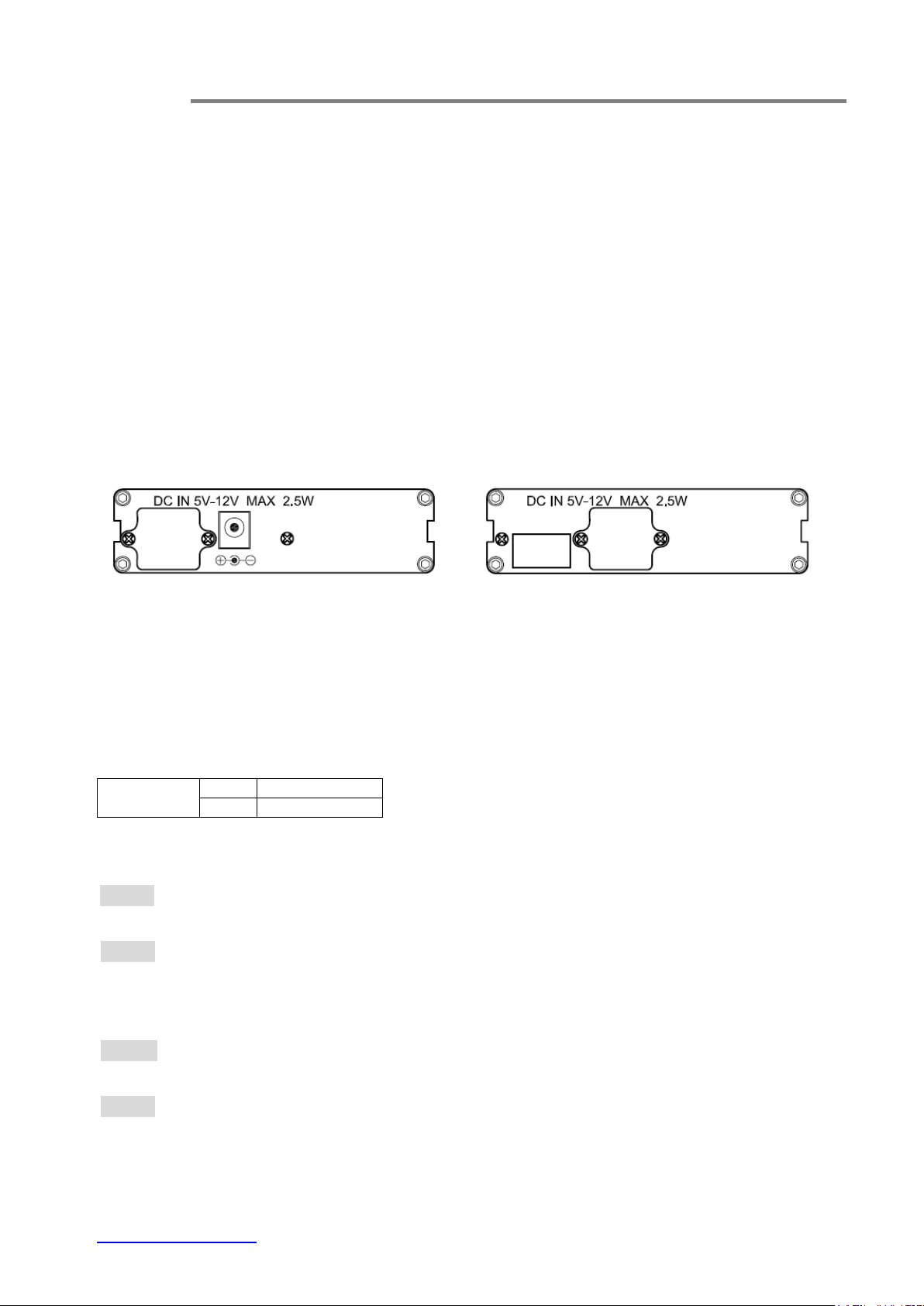
Standalone Wall-mount
Card module
Rear panel
DC IN 12V
Inner
12V
Outer
GND
Size of DC JACK outside diameter (OD): 2.5mm;
Length of the DC Jack:9.5mm
3.3 Selecting a site for the Switch
As with any electric device, you should place the switch where it will not be subjected
to extreme temperatures, humidity, or electromagnetic interference. Specifically, the site
you select should meet the following requirements:
- The ambient temperature should be between -20 to +60 degrees Celsius.
- The relative humidity should be less than 95 percent, non-condensing.
- Surrounding electrical devices should not exceed the electromagnetic field (RFC)
standards.
- Make sure that the switch receives adequate ventilation.
- The power outlet should be within 1.8 meters of the switch.
3.4 Connecting to Power
* The 5-PIN golden finger should be inside the square space that reserve for power input from the 5-PIN connector at ET-C12. The DC
Jack should be covered by the cover panel for power of the card model by using 2 screws.
3.4.1 Standalone Wall-mount
Power Input Assignment
The tip (i.e. the inner conductor) carries the positive (+) pole.
DC Jack Power Input
Step 1: Connect the DC power cord to the DC jack on the rear of switch and then plug it
into a standard DC outlet.
Step 2: Disconnect the power cord if you want to shut down the switch.
3.4.2 Card module
DC Power Input
Step 1: Connect the DC power cord at the rear of ET-PSU/5V and then turn it on for
power up the card modules within the ET-C12.
Step 2: The Card Module can be removed as slide-out module form the ET-C12 (12-slot
Rack Mount Chassis). “Hot-swap” allows any module to be removed and
restored without affecting the operation of any other. Or switch off the
ET-PSU/5V to shut down all switches in the ET-C12.
www.ot-systems.com 8
Page 9
ET2111 Series Installation & Operation Manual
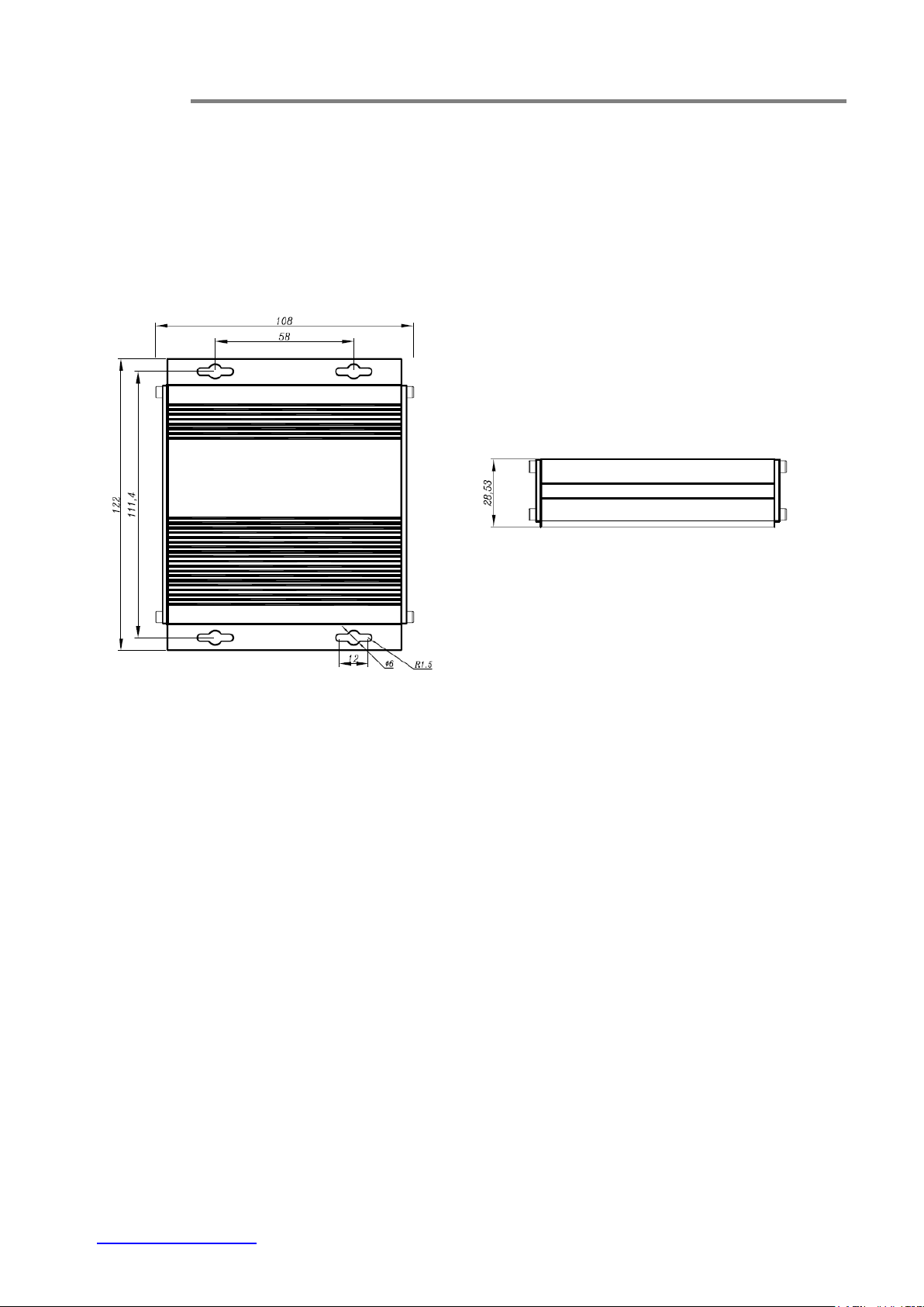
(a) Top view
(b) Side view
3.5 Installation
This chapter gives step-by-step instructions about how to install the switch:
3.5.1 Standalone wall mount type
a) Mount the ET2111 onto a fixture or camera housings, e.g. a plank, (either on the
wall or on a flat surface) with four screws through the holes on the mounting
frame to secure it in position.
Fig. 3.5 Dimension of Micro type units
b) The power supply should also be mounted on the same fixture or in the proximity
for connection of the supply cables to the unit, provided that an AC power supply
socket is nearby for powering the adaptor.
c) Connect all the signal inputs and outputs at the unit with appropriate cables: fiber
optic cable for optical link and UTP/STP Cat 5 cable for Ethernet. Please refer to
Section 4.1 for the details.
d) Once the unit is powered up, check that the POWER LED on the unit is lit. If not,
check the power supply cable connections between the unit and the power
supply socket.
e) With all the signals available at the physical ports, check the status of LEDs
located on the unit. With correct status of each LED, installation is now completed
[for LEDs status, see Operational Guides on this manual’s Section (5)].
www.ot-systems.com 9
Page 10

ET2111 Series Installation & Operation Manual
3.5.2 Card Module
a) Insert the card module into the ET-C12 chassis along the top and bottom card guides of
an empty slot and push the card into the multi-pin socket at the rear firmly. Secure with
the provided thumb screws.
b) Repeat the above procedure for all the rest card modules. Unused slots must be covered
with blank panels provided.
c) Connect all the signal inputs and outputs at the unit with appropriate cables: fiber
optic cable for optical link and UTP/STP Cat 5 cable for Ethernet. Please refer to
Section 4.1 for the details.
d) Once the unit is powered up by ET-PSU/5V, check that the POWER LED on the
unit is lit. If not, check the power supply cable connections between the chassis
and the power supply socket and the connections between the card module and
ET-C12.
e) With all the signals available at the physical ports, check the status of LEDs
located on the unit. With correct status of each LED, installation is now completed
[for LEDs status, see Operational Guides on this manual’s Section (5)].
www.ot-systems.com 10
Page 11
ET2111 Series Installation & Operation Manual
Signal
Type
Cable Type
Connector
For details,
please refer to
Optical
Single-mode or Multi-mode fiber
SC or ST Connector
Section 4.2.2
Ethernet
Twisted-pair Cable
10BASE-T: UTP/STP Cat3, 4, 5
100BASE-TX: UTP/STP Cat 5
RJ45 Connector
Section 4.2.1
12VDC
Power cord
DC JACK (Standalone
Wall-mount type) or
Golden finger (Card Module)
within the ET-C12
Section 3.4
(4) Cable Connections & Setup Procedures
4.1 System cable connections
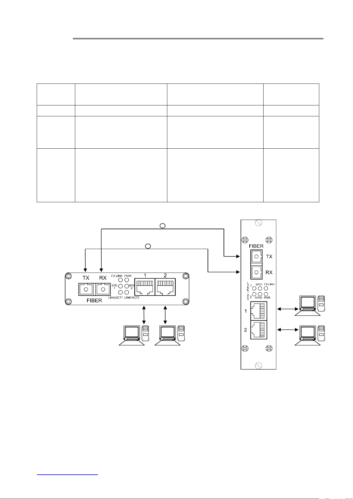
Wiring Diagram
www.ot-systems.com 11
Fig 4.1 Switches connection diagram
Page 12

ET2111 Series Installation & Operation Manual
Speed
Connector
Port Speed
Half/Full Duplex
Cable
Max.
Distance
10Base-T
RJ-45
10/20 Mbps
2-pair UTP/STP Cat. 3, 4, 5
100 m
100Base-TX
RJ-45
100/200 Mbps
2-pair UTP/STP Cat. 5
100 m
100Base-FX
SC, ST
100/200 Mbps
MMF (50 or 62.5μm)
2 km
100Base-FX
SC, ST
100/200 Mbps
SMF (9 or 10μm)
20km
4.2 Connecting to Your Network
Cable Type & Length
It is necessary to follow the cable specifications below when connecting the switch to
your network. Use appropriate cables that meet your speed and cabling requirements.
Cable Specifications
Cabling
Step 1: First, ensure the power of the Switch and end devices are turned off.
<Note> Always ensure that the power is off before any installation.
Step 2: Prepare cable with corresponding connectors for each type of port in use.
Step 3: Consult the previous section for cabling requirements based on connectors and speed.
Step 4: Connect one end of the cable to the Switch and the other end to a desired device.
Step 5: Once the connections between two end devices are made successfully, turn on the power and the
Switch is operational.
4.2.1 The 10/100Base-TX Connector
A standard straight through cable is used for the connection between the Ethernet switch
and device. The products feature an auto-MDIX capability. For the details, Please see Appendix A
for your reference.
www.ot-systems.com 12
Page 13
ET2111 Series Installation & Operation Manual
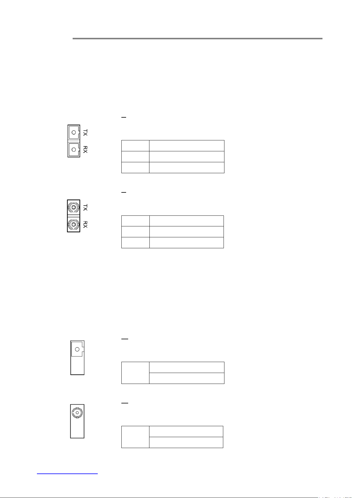
The 100Base-FX Connections
The fiber port pinouts
The TX (transmit) port of device I is connected to the RX (receive) port of device II, and the RX (receive)
port of device I to the TX (transmit) port of device II.
X value:
A for Multimode fiber
B for Singlemode fiber
FIBER
Connector
TX
SC Optical Connector
RX
SC Optical Connector
X value:
G for Multimode fiber
H for Singlemode fiber
FIBER
Connector
TX
ST Optical Connector
RX
ST Optical Connector
The WDM 100Base-FX Connections
The fiber port pinouts
Only ONE optical fiber core is required to transmit and receive data.
* Special note for choosing WDM products:
Pair of products should be used for the optical transmission by different wavelengths (Wavelengths in 1310nm,
1550nm).
i.e. ET2111-C-YY should be match with ET2111-D-YY; ET2111-E-YY should be match with ET2111-F-YY
ET2111-I-YY should be match with ET2111-J-YY; ET2111-K-YY should be match with ET2111-L-YY.
X value:
C and D for Multimode fiber
E and F for Singlemode fiber
FIBER
Connector
SC Optical Connector
X value:
I and J for Multimode fiber
K and L for Singlemode fiber
FIBER
Connector
ST Optical Connector
4.2.2 The 100Base-FX Connectors
www.ot-systems.com 13
Page 14

ET2111 Series Installation & Operation Manual
FIBER -
SC or ST Optical Connector(s) for 100BASE-FX fiber cable connection.
NETWORK -
RJ45 with Cat. 5 for 10/100BASE-TX Ethernet connection.
DC IN-
DC Jack for 5V-12VDC power connection.
LED
State
Indication
PWR
Green
Power on.
Off
Power off.
FX LINK
Green
100Base-FX
SPD1, 2
Green
100Base-TX
Amber
10Base-TX
LINK/
ACT 1, 2
Steady
A valid network connection established
Flashing
Transmitting or receiving data.
ACT Stands for Activity.
(5) Operational Guides
5.1 LEDs Status
5.2 Signal and Power Ports
www.ot-systems.com 14
Page 15

ET2111 Series Installation & Operation Manual
Standards
IEEE 802.3 10BASE-T
IEEE 802.3u 100BASE-TX/FX
IEEE 802.3x
Processing Type
Store-and-Forward
Half-duplex and IEEE802.3x Full-duplex flow control
Forward and Filter Rate
10Base-T
100Base-TX/FX
14,881pps (10Mbps)
148,810pps (100Mbps)
Cabling
10BASE-T
100BASE-TX
UTP/STP Cat. 3, 4, 5 or above
UTP/STP Cat. 5 or above
Maximum Distance
Cat5 UTP
Up to 100m
Connector
10/100BASE-TX
2 X RJ45
Address table size:
2048MAC addresses
Cabling
62.5/125μm (Multi-mode)
9/125μm (Single-mode)
Maximum Distance
Multi-mode fiber
2Km
Single-mode fiber
20Km
Wavelength(s)
1310nm
1310/1550nm
Connector
SC or ST
Input Power
12VDC (DC Jack by power adapter for standalone units)
5VDC (from ET-PSU/5V for card module)
Power Consumption
2.4W Max.
Operating Voltage & Max.
Current Consumption
0.2A @ 12VDC
(6) Specifications
Ethernet
Optical
Electrical and Mechanical
www.ot-systems.com 15
Page 16

ET2111 Series Installation & Operation Manual
Power
Power Status
10/100 TX (Per Port)
Link/Activity, Speed
100FX (Per Port)
Link/Activity
Dimensions
SA: 122 X 30 X 103mm
CM: 130 X 31 X 111mm
Net Weight
SA: 0.33Kg (0.43kg including PA)
CM: 0.33Kg
Casing
Aluminum case
Mounting Options
Wall-Mount
Card Module (in ET-C12 rack mount chassis)
Operating Temperature
-20°C to 60°C (-4°F to 140°F)
Storage Temperature
-40°C to 85°C (-40°F to 185°F)
Humidity
0% - 95% non-condensing
ISO9001
FCC Part 15, Class A
EN55022: 2006 Class A
EN55024: 1998 +A1:2001+A2:2003
LED Indicators
Environmental
Regulatory Approvals
www.ot-systems.com 16
Page 17
ET2111 Series Installation & Operation Manual
(7) Drawings
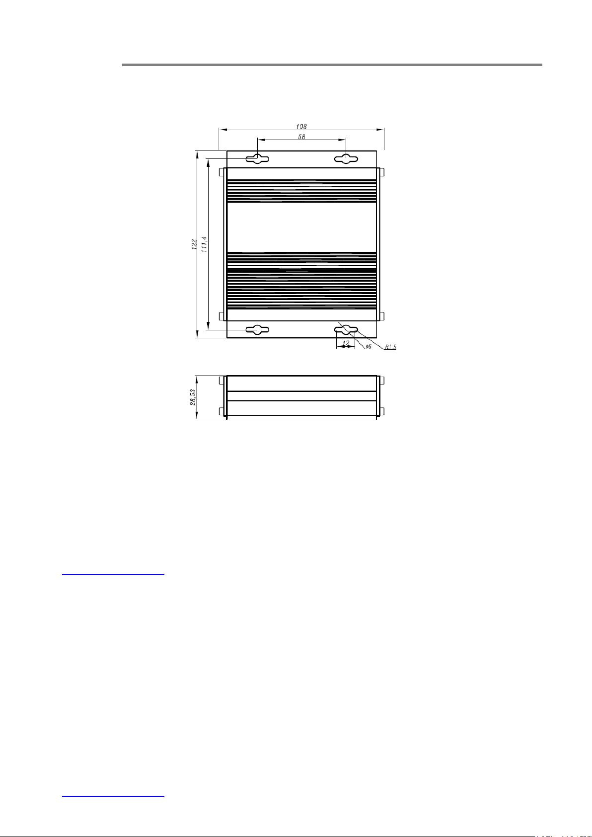
Fig. 7.1 Dimensional drawings of standalone wall-mount ET2111 (mm)
(8) Warranty Information
All OT Systems ET Series products are subject to a three-year limited warranty offered by
the company in normal circumstances. Please refer to the OT Systems Products Warranty
Statement for details. Access to the statement is available in our company website at
www.ot-systems.com.
www.ot-systems.com 17
Page 18

ET2111 Series Installation & Operation Manual
(9) Contact Information
APAC Operation
Address:
Unit 1023, 10/F, Landmark North,
39 Lung Sum Avenue, Sheung
Shui, N.T., Hong Kong
Tel: (852) 2672 5153
Fax: (852) 2679 0756
Sales Inquiries
Technical Support
EMEA Operation
Address:
J. Slovackio str. 4, LT-11107,
Vilnius, Lithuania
Tel: (370) 60730087
Fax: (370) 52051855
Sales Inquiries
Technical Support
AMERICAS Operation
Address:
18 West Main Street, Plano,
IL 60545, U.S.A.
Tel: (1) 630 554 9178
Fax: (1) 630 554 9179
Sales Inquiries
Technical Support
www.ot-systems.com 18
Page 19
ET2111 Series Installation & Operation Manual
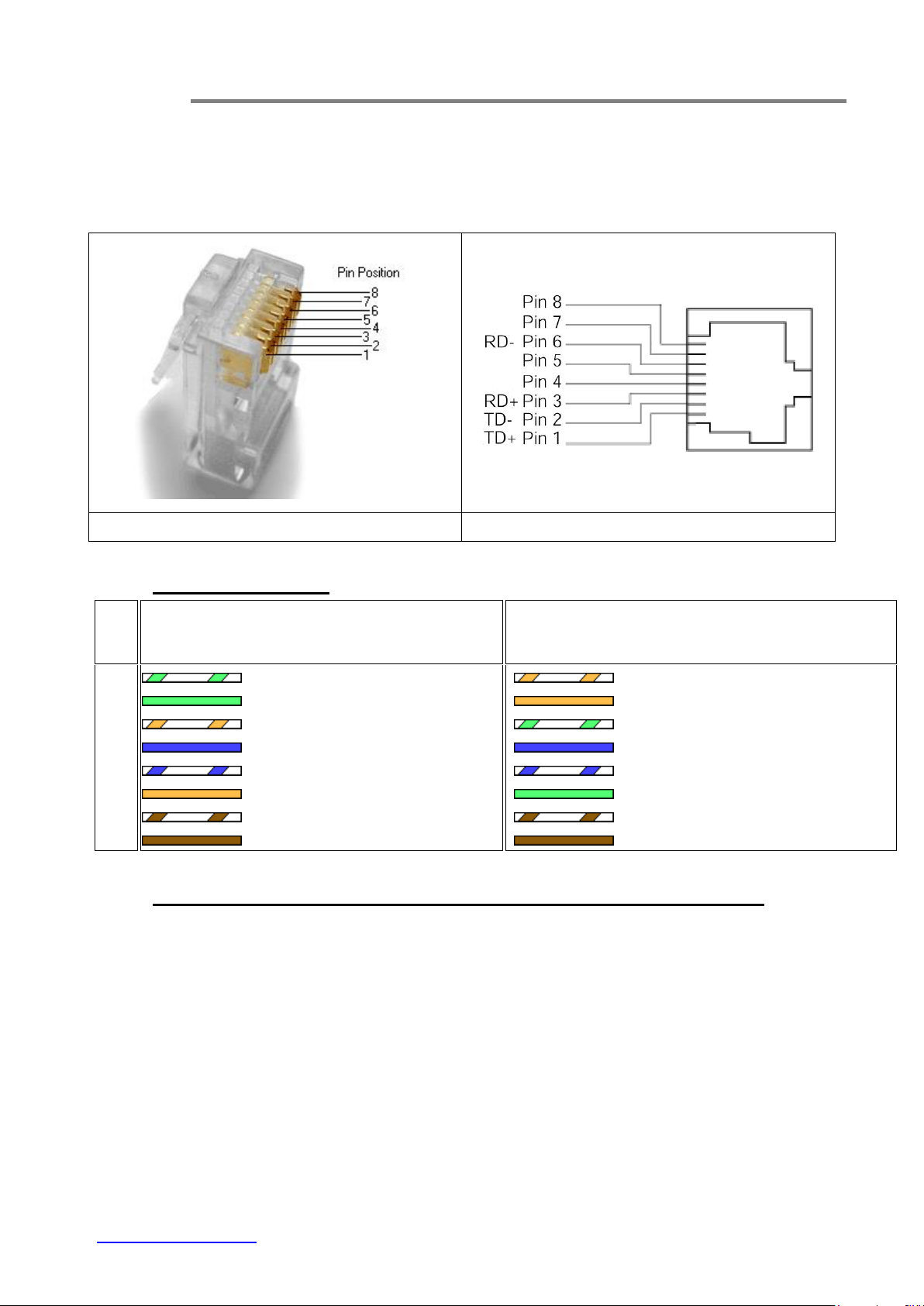
RJ45 Connector (Male)
RJ45 Connector (Female)
RJ45
Pin #
T568A
T568B
Wire Diagram
Wire Color
10Base-T Signal
100Base-TX Signal
Wire Diagram
Wire Color
10Base-T Signal
100Base-TX Signal
1 White/Green
Transmit+
White/Orange
Transmit+
2 Green
Transmit-
Orange
Transmit-
3 White/Orange
Receive+
White/Green
Receive+
4 Blue
Unused
Blue
Unused
5 White/Blue
Unused
White/Blue
Unused
6 Orange
Receive-
Green
Receive-
7 White/Brown
Unused
White/Brown
Unused
8 Brown
Unused
Brown
Unused
Appendix A
1. Connector Pinouts
2. TIA/EIA-568 Cabling
3. Standard, Straight-Through Wiring Diagram(both ends are the same):
The Straight-Through wiring (or called “regular” Ethernet cable), both ends should be use the
same pin out on of RJ45 port.
www.ot-systems.com A
 Loading...