

Page 1
1
ET1111PpH-S-DR/ ET1212PpH-S-DR
Hardened 1-port 100BaseTX to 100Base-FX or 1000Base-T to 1000Base-FX SFP Media Converter with
High Power PoE
This quick start guide describes how to install and use the Hardened SFP Media Converter with High Power PoE. This is the Media Converter of
choice for harsh environments constrained by space.
Overview
ET1111PpH-S-DR/ ET1212PpH-S-DR are a DIN rail type media converter that supports external SFP modules and
meets EN55022 standard. The Ethernet port support high power PoE (Power Sourcing Equipment) which complies
with IEEE 802.3at standard. It is a hardened grade product whose operating temperature range is -40℃ to 75℃ .
ET1111PpH-S-DR supports 100M Ethernet port and 100M SFP port. ET1212PpH-S-DR supports 1000M Ethernet
port and 1000M SFP port. The Ethernet port supports both half-duplex and full-duplex mode. ET1111PpH-S-DR
/ ET1212PpH-S-DR are the same at the transmitter or receiver sides. Users can use different type of SFP modules
(single-mode/multi-mode fiber, 1/2 core) as needed.
General
To ensure trouble free transportation and storage, all OT Systems products must be thoroughly inspected, tested and
properly packed before delivery. Check the product upon receipt for any visible damage which may have been
caused during shipment..
Package Content
ET1111PpH-S-DR/ET1212PpH-S-DR Media Converter x 1
Quick Start Guide x 1
L-shaped wall mount bracket x 1
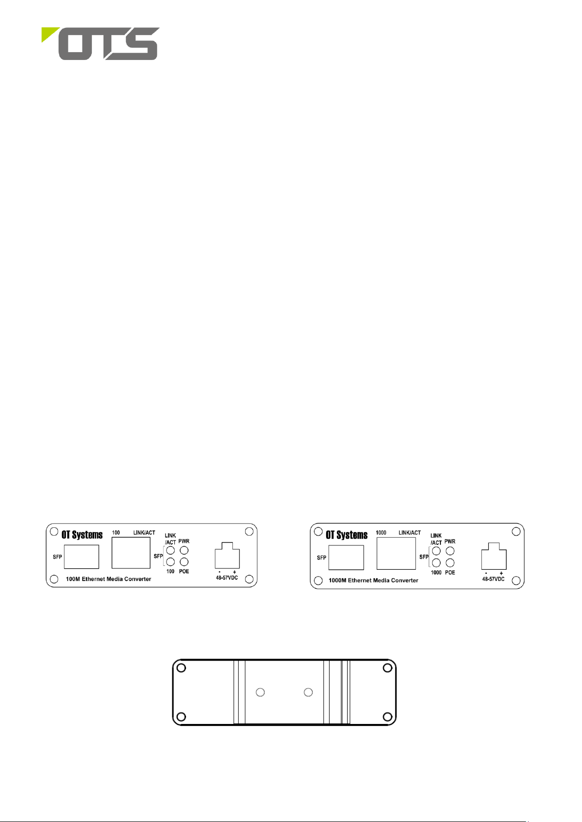
Physical Description
Front Panel
ET1111PpH-S front panel ET1212PpH-S front panel
Rear Panel
V3
Page 2
2
ET1111PpH-S-DR/ ET1212PpH-S-DR
Hardened 1-port 100BaseTX to 100Base-FX or 1000Base-T to 1000Base-FX SFP Media Converter with
High Power PoE
Installation
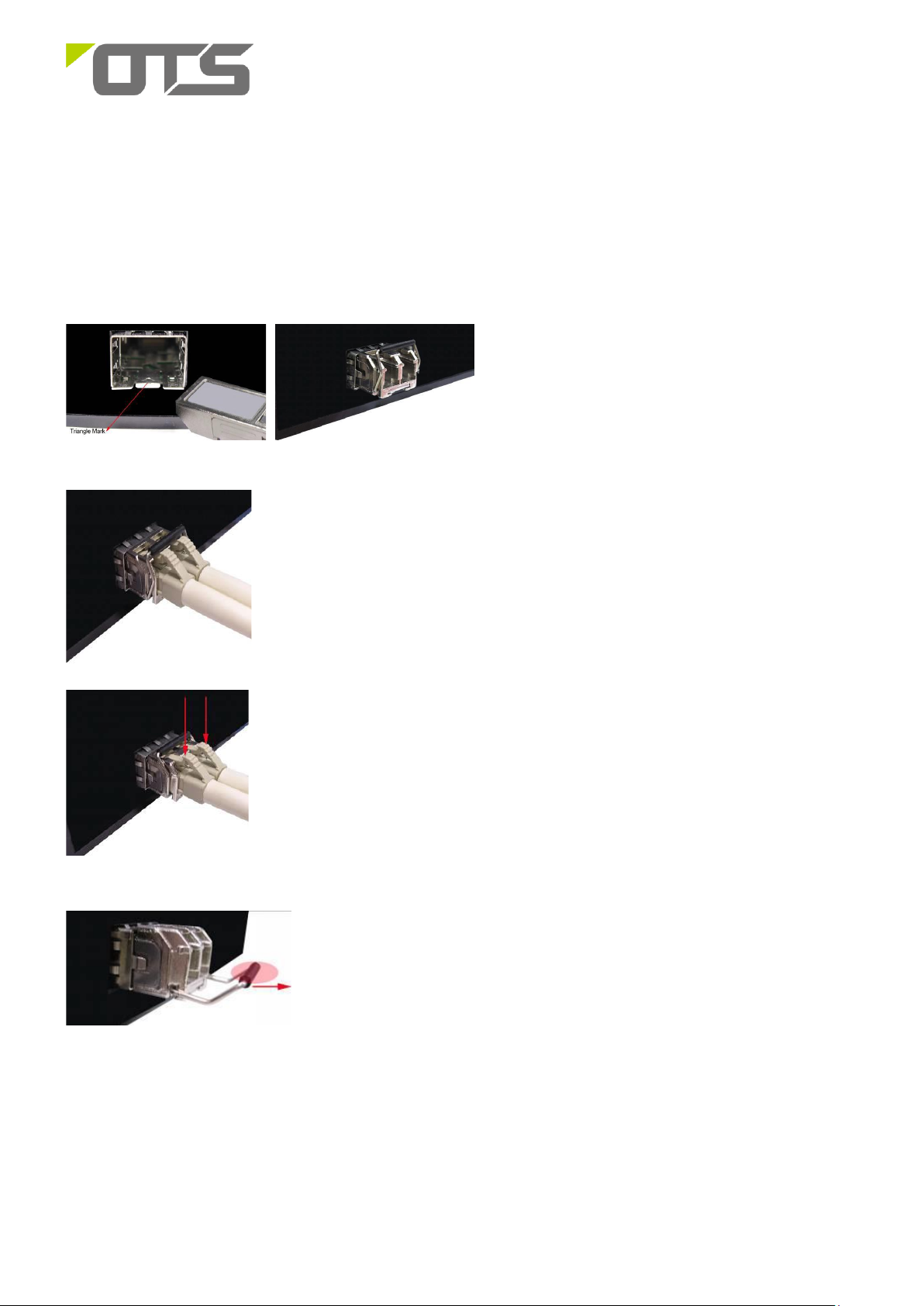
SFP Transceiver Module
You can select different SFP modules as required (Please refer to our SFP selection list for the appropriate module).
To insert/remove the SFP, the procedures are as follow:
1. On the side panel, insert the SFP module into the
SFP port until it is securely locked.
2. Connect the optical fiber (1/2 core) to the LC connector(s) of the SFP.
3. To remove the SFP module, press down the lock of the LC connector of the optical
fiber to pull out the fiber cable.
SFP port.
4. Pull down the SFP lever and hold its position. Pull out the SFP module from the
V3
Page 3

3
1. Tighten the screws to fix the
DIN Rail plate
1. Tighten the screws to fix the
wall mount bracket
2. Mount the switch on the wall
or on a flat surface with 2 screws
piercing through the mounting
holes to secure it in position.
Upper part
2. Lock the upper part of the DIN
rail clip on the upper side of the
track. Gently press it until the clip
is securely locked on the track.
Press
ET1111PpH-S-DR/ ET1212PpH-S-DR
Hardened 1-port 100BaseTX to 100Base-FX or 1000Base-T to 1000Base-FX SFP Media Converter with
High Power PoE
DIN Rail Installation
ET1111PpH-S-DR/ET1212PpH-S-DR can be installed on a DIN rail. Installation steps are as follows:
Wall Mount Installation
ET1111PpH-S-DR/ET1212PpH-S-DR can also be installed on a wall or a flat surface. Installation steps
are as follows:
Setup
a) Connect the Ethernet port of the media converter to a PoE IP camera (PoE device) or network device with a
network cable.
b) Insert the appropriate SFP into the SFP port. Connect the fiber cable from the device (media converter or
switch) on the other end to the LC connector of the SFP.
c) After the device is powered on, the PWR indicator will all be on. If the indicators are not on, check the power
supply connection.
d) After all cables are correctly connected, the indicators will be lit as per port status LEDs (page 3)..
V3
Page 4
4
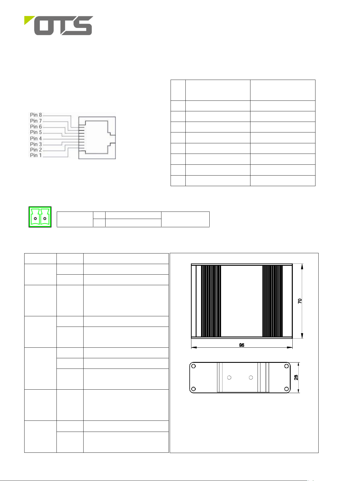
Ethernet Port
RJ-45 Pin Assignment
.
Pin
ET1111PpH-S
Signal Definition
ET1212PpH-S
Signal Definition
1
TD+
TP0+
2
TD-
TP0- 3 RD +
TP1+
4
Positive (VCC+)
TP2+ / VCC+
5
Positive (VCC+)
TP2- / VCC+
6
RD-
TP1-
7
Negative (VCC-)
TP3+ / VCC-
8
Negative (VCC-)
TP3- / VCC-
LED
State
Indication
PWR
Green
Power on.
Off
Power off.
100
1000
(SFP)
Green
100Base-FX Fiber link stable
1000Base-FX Fiber link stable
LINK/ACT
(SFP)
Steady
A valid fiber connection established
Flashing
Transmitting or receiving data.
ACT Stands for Activity.
PoE
Green
PoE is activated.
Flashing
A Power Device (PD) is being detected.
Off
No device is connected or the connected
device is not a PD.
100
1000
(RJ45)
Green
100Base-TX
1000Base-TX.
LINK/ACT
(RJ45)
Steady
A valid network connection established
Flashing
Transmitting or receiving data.
ACT Stands for Activity.
48~57VDC
-
GND
Terminal Block
+
48~57V
Top View
Side View
- +
ET1111PpH-S-DR/ ET1212PpH-S-DR
Hardened 1-port 100BaseTX to 100Base-FX or 1000Base-T to 1000Base-FX SFP Media Converter with
High Power PoE
Interface
Power Connection
The Port Status LEDs, dimension drawing
V3
Page 5

5
ET1111PpH-S-DR/ ET1212PpH-S-DR
Hardened 1-port 100BaseTX to 100Base-FX or 1000Base-T to 1000Base-FX SFP Media Converter with
High Power PoE
Functional Description
Converts100Base-TX port to 100Base-FX (ET1111PpH-S-DR) or 1000Base-T port to 1000Base-X (ET1212PpH-S-DR).
Supports IEEE802.3at Power over Ethernet (POE+)
Supports Full/Half duplex.
Supports External SFP.
Supports Auto-MDI/MDIX.
Support DIN-Rail and Wall-mount installation
Extensive LED indicators for network diagnostics
Environmentally hardened -40℃ to 75℃ (-40℉ to 167℉) operating temperature.
Manual Earth Green manual is available in our website. www.ot-systems.com
V3
 Loading...