

Page 1
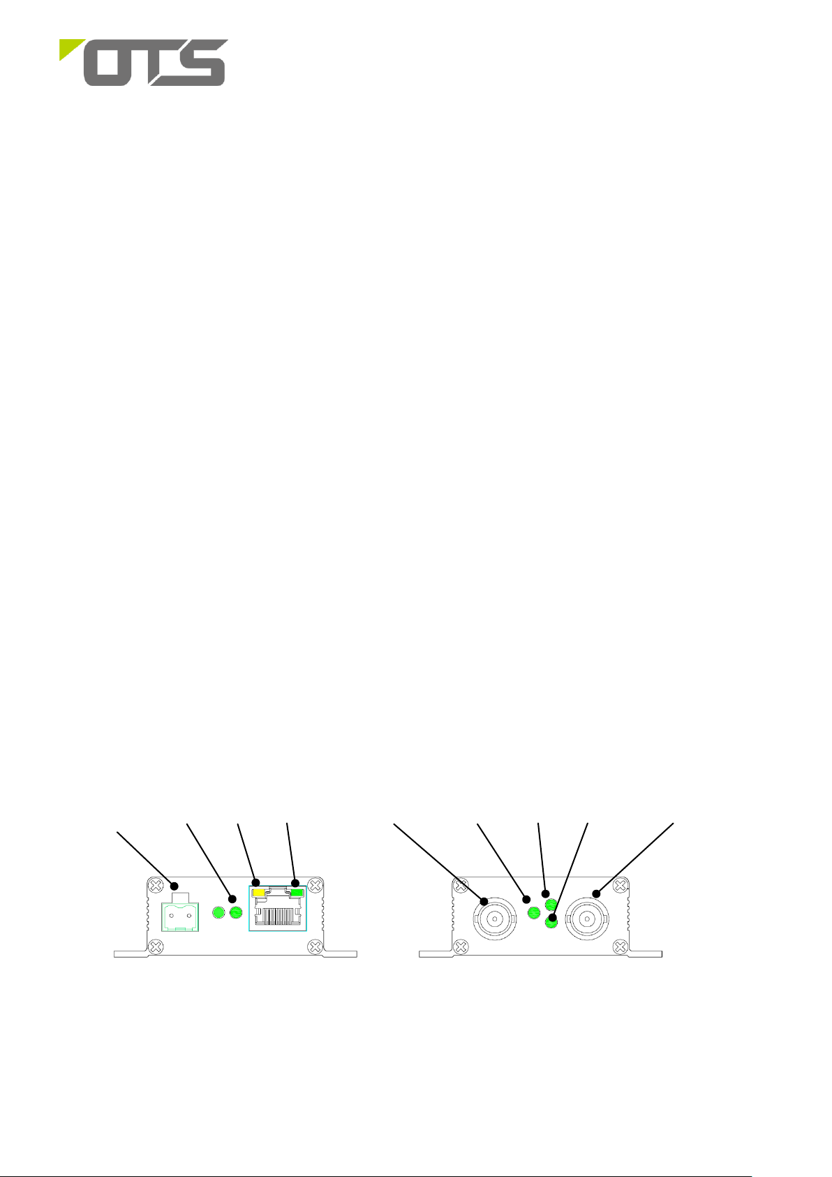
Power Input
Coax Data
SPD
PWR
CVBS
Input / Output
CVBS
In/Out
Link/ACT
ACT
LINK
ET1100C2 Series
Industrial 10/100Base-TX Ethernet plus CVBS Over Coax Converter
This quick start guide describes how to install and use the Industrial Coaxial Converter. This is the Coaxial Converter
of choice for harsh environments constrained by space.
Overview
ET1100C2 is a pair of 10/100Base-TX Ethernet plus CVBS (composite video baseband signal) over coax converters.
It completely complies with the international standards such as IEEE 802.3 10Base-T, IEEE802.3u 100Base-TX,
and IEEE 802.3X.
The product series consists of a transmitter (ET1100C2-T) and receiver (ET1100C2-R). The maximum transmission
distance of a coaxial cable is 300m. The ET1100C2 series products can transmit not only the existing CVBS over the
coaxial cable, but also the IP signals of network products (e.g. IP cameras) at the same time. With ET1100C2 series
products, it is a cost effective way to upgrade the analogue video surveillance system to workable with the IP
cameras to the video surveillance system without laying the cable again.
General
To ensure trouble free transportation and storage, all OT Systems products must be thoroughly inspected, tested
and properly packed before delivery. Check the product upon receipt for any visible damage which may have been
caused during shipment.
Package Content
Transmitter (ET1100C2-T) or Receiver (ET1100C2-R) of Ethernet Extender over Coaxial Converter x1
Power Adapter x 1
Quick Start Guide x 1
Physical Description
Front/Rear Panel
1 V1.3
Page 2
Coaxial line
Network
cable
Network
cable
Camera
Display
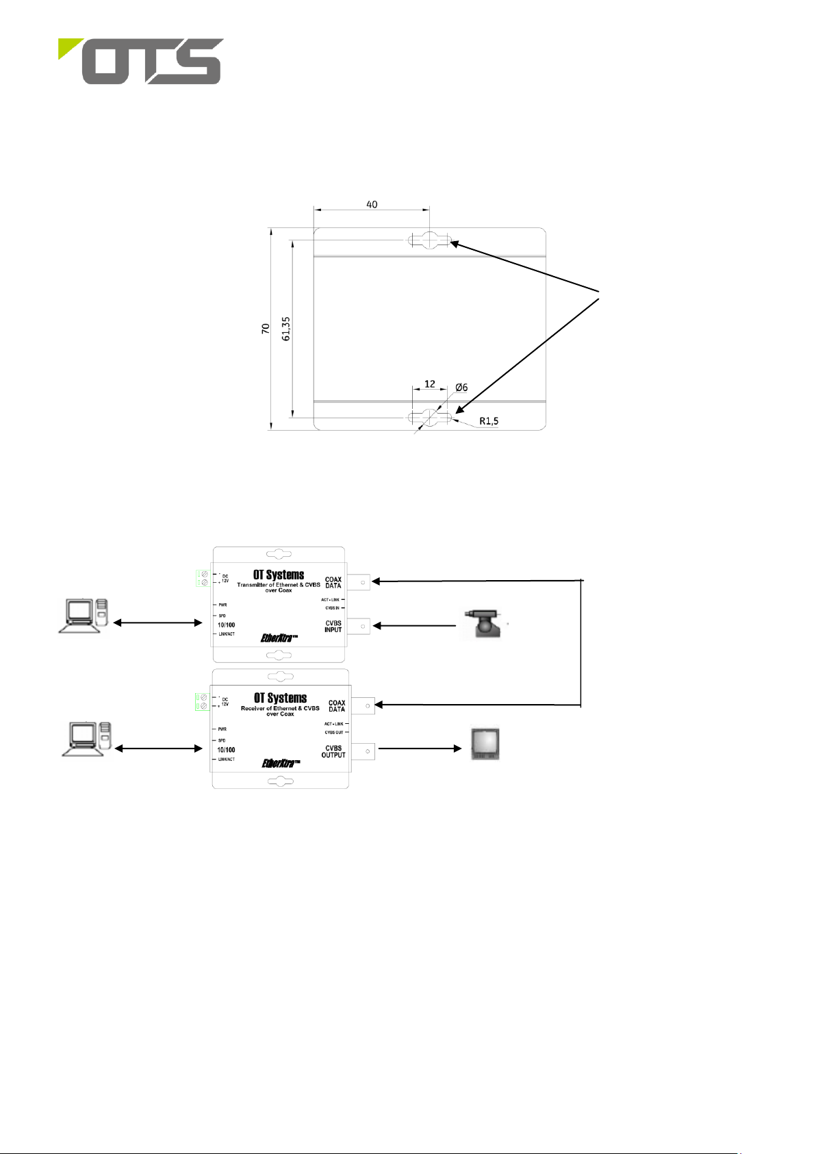
Mounting holes
ET1100C2 Series
Industrial 10/100Base-TX Ethernet plus CVBS Over Coax Converter
Installation
a) The product has two mounting holes. See Figure 1 for its structure. Mount the product on wall or a flat surface.
Figure 1. Case dimensions
b) Typical cable connection diagram:
Installation Steps
a) Connect the COAX DATA connector of the transmitter (TX) and receiver (RX) with coaxial cable.
b) At TX side, connect the analogue camera video signal to the CVBS INPUT connector with coaxial cable, the IP
camera signal to the Ethernet port (10/100) with network cable.
c) At RX side, connect the monitor to the CVBS OUTPUT with the coaxial cable, the NVR/switch to the Ethernet
port (10/100) with network cables to the switch or PC.
d) The PWR light is on when the product is powered on. Check if the power cable is working properly.
e) After all cables are correctly connected, the indicators will be lit as per port status LEDs (page 3).
2 V1.3
Page 3

10/100M Ethernet port pin sequence diagram:
Pin
MDI Signal Definition
MDIX Signal
Definition
1
TD+
RD +
2
TD-
RD-
3
RD +
TD+
4
NC
NC
5
NC
NC
6
RD-
TD-
7
NC
NC
8
NC
NC
12VDC
-
GND
Terminal Block
+
12V
- +
ET1100C2 Series
Industrial 10/100Base-TX Ethernet plus CVBS Over Coax Converter
Interface
Ethernet Port:
a) Ethernet port RJ45:
Power Connection
3 V1.3
Page 4

Indicator
Color
Description
PWR
Green
Power on.
Off
Power off.
COAX
DATA
LINK
Green
The COAX DATA link
(between TX & RX) is
established.
ACT
Flashing
Data is being
transmitted or received.
ACT Stands for Activity.
CVBS IN (TX only)
Green
Video input
CVBS OUT (RX only)
Green
Video output
10/100
(Ethernet)
SPD
Orange
100Base-TX
Off
10Base-TX
LINK/ACT
Steady
A valid network
connection is
established
Flashing
Data is being
transmitted or received.
ACT Stands for Activity.
ET1100C2 Series
Industrial 10/100Base-TX Ethernet plus CVBS Over Coax Converter
The Port Status LEDs, dimension drawing of the Micro unit
Functional Description
Ethernet Extension : Security Link over Coax
Simultaneous transmission of IP and CVBS over single coaxial cable
Constant Data Rate : 36Mbps(Downlink)/11Mbps(Uplink)
Maxiumum distance : 300m over Coax(RG-59/U)
Support Auto MDI/MDI-X
-10℃ to 60℃ operating temperature.
Assembly, Startup, and Dismantling
Installation
Installation: Mount the Micro type unit onto a fixture, or camera housings, e.g. a plank, (either on the wall or on
a flat surface) with at least 2 screws piercing through the holes on the mounting frame to secure it in position.
Startup: Connect the supply voltage to start up the Media Converter via the terminal block.
Dismantling: Locate and remove the securing screws. Usually, but not limited to, at least 2 screws.
Manual Earth Green manual is available on our website www.ot-systems.com
4 V1.3
 Loading...