

OTS FT010AF-SSTLSA, FT010AF-SST, FT010AF-SSTL, FT010AF-SSR, FT010AF-SSRL Installation And Operation Manual
...Page 1
FT010AF Series Installation & Operation Manual
www.ot-systems.com 1
Installation and Operation Manual
FT010AF Series
Digital Series
1-Ch Forward Audio
Fiber Optic Converter
OT Systems Ltd., 2014
Rev 1.2
Page 2

FT010AF Series Installation & Operation Manual
www.ot-systems.com 2
Models covered in this manual
Standalone Units
Single-Mode Transmitters
FT010AF-SSTSA
FT010AF-SSTLSA
Single-Mode Receivers
FT010AF-SSRSA
FT010AF-SSRLSA
Multi-Mode Transmitter
FT010AF-SMTSA
Multi-Mode Receiver
FT010AF-SMRSA
Card Modules
Single-Mode Transmitters
FT010AF-SST
FT010AF-SSTL
Single-Mode Receivers
FT010AF-SSR
FT010AF-SSRL
Multi-Mode Transmitter
FT010AF-SMT
Multi-Mode Receiver
FT010AF-SMR
Remark:
If the optical connector is FC type, the suffix in the model number will be “-FXX”. Eg.
FT010AF-FST
Page 3

FT010AF Series Installation & Operation Manual
www.ot-systems.com 3
Table of Contents
(1) SAFETY INSTRUCTIONS .................................................................................................................................. 4
(2) PRODUCT OVERVIEW .................................................................................................................................... 5
2.1 INTRODUCTION ..................................................................................................................................................... 5
2.2 MODELS SELECTION TABLE ...................................................................................................................................... 6
(3) INSTALLATION................................................................................................................................................ 7
3.1 GENERAL ............................................................................................................................................................. 7
3.2 STANDALONE UNIT INSTALLATION .............................................................................................................................. 7
3.3 CARD MODULE INSTALLATION................................................................................................................................... 8
(4) CABLE CONNECTIONS & SETUP PROCEDURES ................................................................................................ 8
4.1 SYSTEM CABLE CONNECTIONS ................................................................................................................................. 8
4.2 AUDIO CONNECTIONS ........................................................................................................................................... 10
4.3 GROUND CONNECTION ......................................................................................................................................... 11
(5) OPERATIONAL GUIDES ................................................................................................................................. 12
5.1 FT010AF SERIES TRANSMITTER ............................................................................................................................ 12
5.2 FT010AF SERIES RECEIVER .................................................................................................................................. 12
(6) SPECIFICATIONS ........................................................................................................................................... 13
(7) DRAWINGS .................................................................................................................................................. 14
(8) WARRANTY INFORMATION ......................................................................................................................... 14
(9) CONTACT INFORMATION ............................................................................................................................. 15
Page 4

FT010AF Series Installation & Operation Manual
www.ot-systems.com 4
(1) Safety Instructions
Please be familiar with all information in this manual prior to installation and
operation.
Note 1: The products described contain a Class 1 laser or LED fiber optic emitter. The following
safety precautions apply.
Warning: Do not disconnect the fiber optic connector while the unit is powered up.
Exposure to Class I invisible optical radiation is possible when the internal fiber optic
connector is disconnected while the unit is powered up.
Caution: Any access to the controls, adjustments, or performing operations, which are
other than those specified may result in hazardous radiation exposure. Permanent eye
damage or other bodily injuries may be resulted from such exposure even for only
seconds.
Note 2: This assembly contains parts sensitive to damage by electrostatic discharge (ESD). ESD
precautionary procedures should be applied in the course of touching, removing or inserting parts
or assemblies.
Page 5

FT010AF Series Installation & Operation Manual
www.ot-systems.com 5
(2) Product Overview
2.1 Introduction
The FT010AF Series products comprise of either single-mode or multi-mode fiber optic
transmitters and receivers for the optical transmission of ONE bi-directional (Tx ↔ Rx) audio
signal on one fiber. The products work at wavelengths of 1310nm or 1550nm with either a
9/125um or 62.5/125um fiber for single-mode or multi-mode transmission respectively.
A 24-bit digital PCM transmission scheme is employed for analogue audio transmission.
Both balanced and unbalanced audio inputs and outputs are supported. Optical Wavelength
Division Multiplex (WDM) technique is also employed for simultaneous reverse audio signal
transmission.
For single-mode transmission, we also offer specifically designed products for long-haul
transmissions up to 60km. These models include the letter “L” in the suffix, e.g. FT010AF-SSTL
for Tx, FT010AF-SSRL for Rx, etc.
The FT010AF Series units are available as standalone units, which can be mounted
horizontally or vertically wall-mounted on any fixture. The standalone unit comes with an external
power supply FT-PA/12V, which can be powered by local 110/220V power.
The FT010AF Series units are also available as plug-in card modules installed in a 19”
rack-mount chassis. Each plug-in card occupies one slot in the rack-mount chassis. The rack
mount chassis has to be ordered separately, and comes with its own power supply for powering
the installed card modules.
Page 6

FT010AF Series Installation & Operation Manual
www.ot-systems.com 6
2.2 Models selection table
Type
Mode
Models1
Descriptions
Installation
requirements
Remarks
Standalone Units
Single-Mode
FT010AF-SSTSA
Single-mode 1 forward Audio Transmitter
Standalone unit
Horizontally
or vertically
wall-mounted
Standalone
unit
FT-PA/12V
external
power
supply is
included for
the
Standalone
unit
2
FT010AF-SSTLSA
Single-mode Long-haul 1 forward Audio
Transmitter Standalone unit
FT010AF-SSRSA
Single-mode 1 forward Audio Receiver
Standalone unit
FT010AF-SSRLSA
Single-mode Long-haul 1 forward Audio
Receiver Standalone unit
Multi-Mode
FT010AF-SMTSA
Multi-mode 1 forward Audio Transmitter
Standalone unit
FT010AF-SMRSA
Multi-mode 1 forward Audio Receiver
Standalone unit
Card Modules
Single-Mode
FT010AF-SST
Single-mode 1 forward Audio Transmitter
Card Module
Housed in
FT-C18
chassis
3
FT-C18
chassis has
to be
ordered
separately
FT010AF-SSTL
Single-mode Long-haul 1 forward Audio
Transmitter Card Module
FT010AF-SSR
Single-mode 1 forward Audio Receiver
Card Module
FT010AF-SSRL
Single-mode Long-haul 1 forward Audio
Receiver Card Module
Multi-Mode
FT010AF-SMT
Multi-mode 1 forward Audio Transmitter
Card Module
FT010AF-SMR
Multi-mode 1 forward Audio Receiver Card
Module
1
If the optical connector is FC type, the suffix in the model number will be “-FXX”. Eg. FT010AF-FST
2
FT-PA/12V works under 100 -240VAC, 50/60Hz power supply
3
Refer to FT-C18 product manual for specifications
Page 7

FT010AF Series Installation & Operation Manual
www.ot-systems.com 7
(3) Installation
3.1 General
All OT Systems products are thoroughly inspected, tested and securely packaged before
delivery to ensure a stable, intact and trouble-free service. Please check the equipment upon
receipt for any visible damage which may have been caused during shipping.
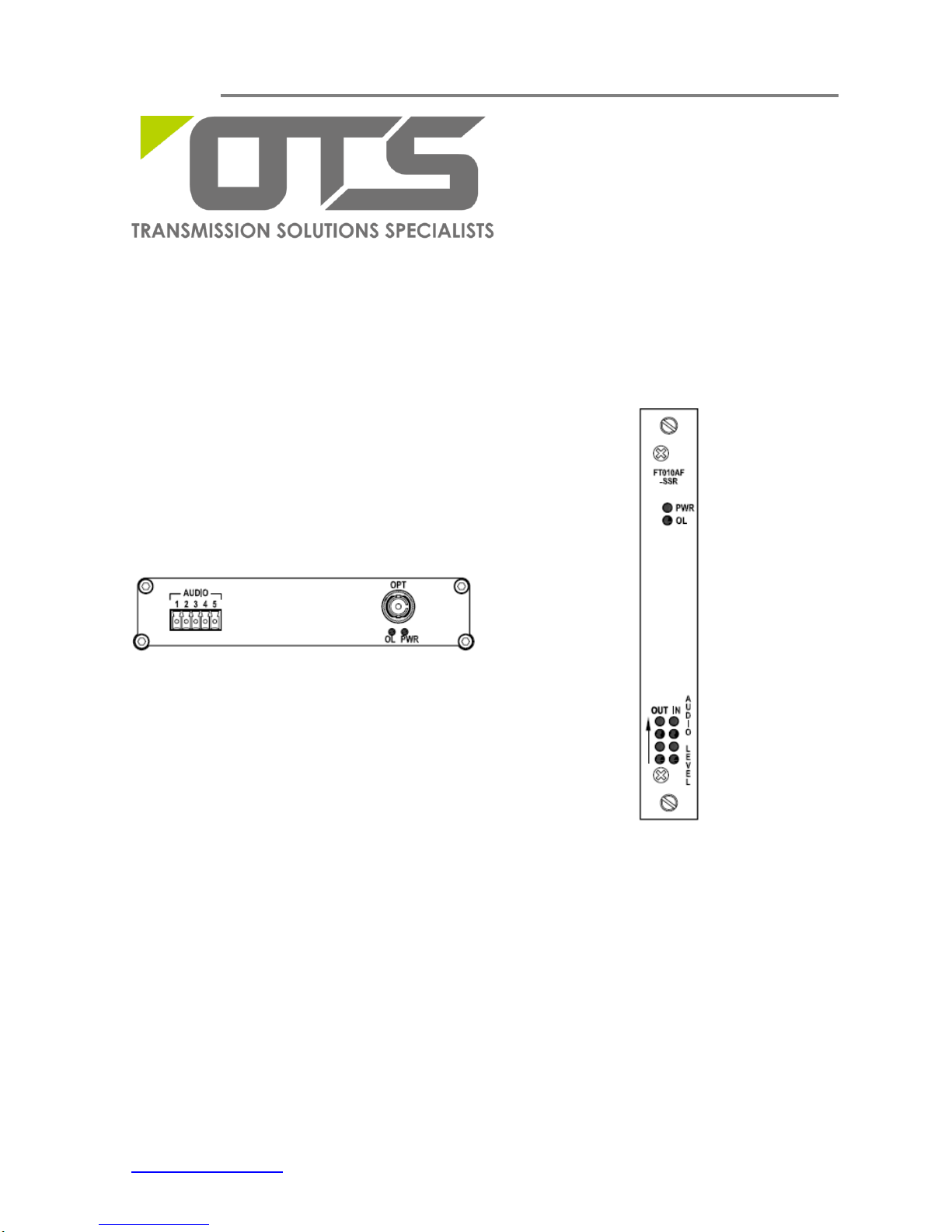
The FT010AF Series standalone units (Fig.3.1) can be either horizontally or vertically
wall-mounted, or mounted on any fixture. The Standalone unit works with an external power
supply FT-PA/12V powered by local 110/220V power.
The FT010AF Series card modules are housed inside the FT-C18 rack-mount chassis (Fig.
3.2) with an included power supply unit. The whole chassis is powered by local 110/220V power.
FT-C18 is a standard 19” (483mm) rack-mount chassis which occupies 4 rack units (177.8mm) in
height. Each FT010AF card module occupies one slot and a total of 18 cards can be housed
inside the chassis.
3.2 Standalone unit installation
a) Mount the standalone unit onto a fixture, (either on the wall or on a flat surface) with four
screws through the holes on the mounting frame to secure it in position.
b) The provided power supply should also be mounted on the same fixture or in the proximity
for connection of the supply cables to the unit, provided that an AC power supply socket is
nearby for powering the adaptor.
c) Connect all the signal inputs and outputs at the back of the unit with appropriate cables:
fiber optic cable for optical link, UTP cable for audio input/output (Tx/Rx).
d) Once the unit is powered up, check that the red POWER LED on the unit is lit. If not, check
the power supply cable connections between the unit and the power supply socket.
e) With all the signals available at the input and output ports, check the status of LEDs located
on the unit. With correct status of each LED, installation is now completed [for LEDs status, see
Operational Guides on this manual’s section (5)].
Fig. 3.1 Standalone unit
Fig. 3.2 FT-C18 chassis
Page 8

FT010AF Series Installation & Operation Manual
www.ot-systems.com 8
3.3 Card module installation
a) Insert the card module into the FT-C18 chassis along the top and bottom card guides of an
empty slot and push the card into the multi-pin socket at the rear firmly. Secure with the provided
thumb screws.
b) Repeat the above procedure for all the rest card modules. Unused slots must be covered
with blank panels provided.
c) Connect all the signal inputs and outputs at the back of the unit with appropriate cables:
fiber optic cable for optical link, UTP cable for audio input/output (Tx/Rx).
d) Once the chassis is powered up, check that the red POWER LED on the front and back
panels of the card modules are lit. If not, check the power supply cable connections between the
chassis and the power supply socket. For failures of individual card’s POWER LEDs, check the
corresponding card modules, whether they have been inserted properly.
e) With all the signals available at the input and output ports, check the status of LEDs located
on the unit. With correct status of each LED, installation is now completed [for LEDs status, see
Operational Guides on this manual’s section (5)].
(4) Cable Connections & Setup Procedures
4.1 System Cable Connections
Signal Type
Cable Type
Connector
Optical
Single-mode or Multi-mode fiber
ST (or FC) Connector
Audio
Twisted-pair cable
Screw Terminal Block
Typical System Cable Connections Diagrams:
Standalone Transmitter Standalone Receiver
Fig. 4.1 Standalone unit to Standalone unit connection diagram
Page 9

FT010AF Series Installation & Operation Manual
www.ot-systems.com 9
Standalone Transmitter Card Module Receiver
Fig. 4.2 Standalone unit to Card Module connection diagram
Card Module Transmitter Card Module Receiver
Fig. 4.3 Card Module to Card Module connection diagram
Page 10

FT010AF Series Installation & Operation Manual
www.ot-systems.com 10
4.2 Audio connections
For audio input and output connections, please note the following pin assignment:
Pin Assignment
(Screw Terminal
Block)
Data format
1 2 3 4 5
Balanced signal
IN (+)
IN(-)
OUT(+)
OUT(-)
N/A
Un-Balanced signal
IN
Sig. COM
PIN2 connect to PIN5
OUT
Sig. COM
PIN4 connect to PIN5
Balanced Audio signal connection diagram:
Transmitter End Receiver End
User’s Equipment
AUDIO PORT
(5-PIN)
AUDIO PORT
(5-PIN)
User’s Equipment
Audio OUT(+)
1 IN(+)
1 N/A
Audio OUT(-)
2 IN (-)
2 N/A
3 N/A
3 OUT(+)
Audio IN(+)
4 N/A
4 OUT(-)
Audio IN (-)
5 N/A
5 N/A
Fig. 4.4.1 Connector Pin Assignments for balanced audio signal at Audio port
Un-Balanced Audio signal connection diagram:
Transmit End Receive End
User’s
Equipment
AUDIO PORT
(5-PIN)
AUDIO PORT
(5-PIN)
User’s
Equipment
Audio OUT
1 IN
1 N/A
2 Sig. COM
2 N/A
3 N/A
3 OUT
Audio IN
4 N/A
4 Sig. COM
Sig. COM
5 Sig. COM
5 Sig. COM
Sig. COM
*Jumper wires provided and connected by customer
Fig. 4.4.2 Connector Pin Assignments for un-balanced audio signal at Audio port
*Jumper wires
Page 11

FT010AF Series Installation & Operation Manual
www.ot-systems.com 11
4.3 Ground connection
For enhanced safety to reduce the risks of electrical shock and physical damage, caused by
lightning and other power surges, as well as a connection to the surge suppresion devices in the
product, a screw terminal is provided on the Standalone cabinets (Fig. 4.5). It is highly
recommended that the Standalone unit have good ground connections to the buildings ground in
accordance with the local codes.
Fig. 4.5 Standalone unit earth ground terminal location
Page 12

FT010AF Series Installation & Operation Manual
www.ot-systems.com 12
(5) Operational Guides
5.1 FT010AF Series Transmitter
LED Indicators
Indicator
Color
Description
PWR
Red
Lit when power is supplied to the Transmitter.
OL
Yellow
Lit when optical signal from receiver to transmitter is active.*
Audio Level
(front panel)
IN
Red
a) Each audio channel has a single column of Four LEDs assigned
for displaying the input or output audio levels.
b) The LEDs (Input/Output) are lit in proportion to the signal strength.
c) An increase/decrease of signal level of about 3dB will light up/turn
off an individual LED. All LEDs will go out at or less than -16dBm,
and all are lit when the level attains +6dBm or over.
OUT
N/A
* For products with uni-directional signal transmission, the OL LED on the Tx is not lit because optical signal from the Rx to the Tx is
always inactive.
Signal Ports
OPT -
ST (or FC) Optical Connector for fiber cable connection.
AUDIO -
5-pin Screw Terminal Block for audio signal.
5.2 FT010AF Series Receiver
LED Indicators
Indicator
Color
Description
PWR
Red
Lit when power is supplied to the Receiver.
OL
Yellow
Lit when optical signal from transmitter to receiver is active.
Audio Level
(front panel)
IN
N/A
a) Each audio channel has a single column of Four LEDs assigned
for displaying the input or output audio levels.
b) The LEDs (Input/Output) are lit in proportion to the signal strength.
c) An increase/decrease of signal level of about 3dB will light up/turn
off an individual LED. All LEDs will go out at or less than -16dBm,
and all are lit when the level attains +6dBm or over.
OUT
Green
Signal Ports
OPT -
ST (or FC) Optical Connector for fiber cable connection.
AUDIO -
5-pin Screw Terminal Block for audio signal.
Page 13

FT010AF Series Installation & Operation Manual
www.ot-systems.com 13
(6) Specifications
MODELS*
PARAMETERS
FT010AF-SST(R)SA
FT010AF-SST(R)
(Single-Mode)
FT010AF-SST(R)LSA
FT010AF-SST(R)L
(Single-Mode)
FT010AF-SMT(R)SA
FT010AF-SMT(R)
(Multi-Mode)
OPTICAL
No. of Fiber / Connector
1 / ST (or FC)
1 / ST (or FC)
1 / ST (or FC)
Wavelength
1310 nm
1310 nm
1310 nm
Optical Power Budget
17 dB
24 dB
23 dB
Max Distance
40 km
60 km
4 km
AUDIO
Channel / Connector
1 / 5-pin Screw Terminal
Direction
Bi-directional (Duplex)
Input Level / Impedance
0dBm(normal), 10K ohms, Balanced or Unbalanced
Audio bandwidth
20Hz~20KHz
Output Level
4dBm@1KHz
SNR
>70dB
POWER
Power consumption
12VDC @ 3W
Power Supply
Standalone unit: FT/PA12V DC Adaptor
Card module: Powered by FT-C18 chassis
Connector (Standalone unit)
2-pin Screw Terminal
PHYSICAL
Weight (Kg)
Standalone unit: 0.58 Card module: 0.2
Dimensions (W x H x D) (mm)
Standalone unit: 156 x 30.5 x 223 (MAX)
Card module: 148 x 20.4 x 213 (MAX)
ENVIRONMENTAL
Operating Temperature
-40oC ~ +75oC
Storage Temperature
-40oC ~ +85oC
Relative Humidity
0 ~ 95% non-condensing
MTBF
>100’000 Hours
*If the optical connector is FC type, the suffix in the model number will be “-FXX”. Eg. FT010AF-FST
Page 14
FT010AF Series Installation & Operation Manual
www.ot-systems.com 14
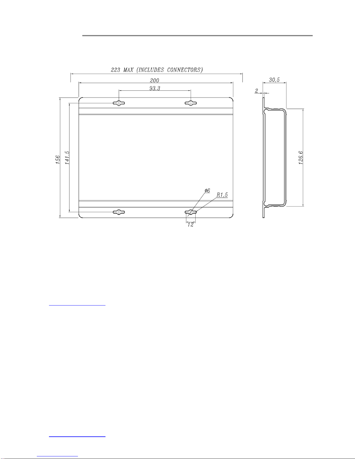
(7) Drawings
Fig. 7.1 Dimensional drawings of Standalone unit (mm)
(8) Warranty Information
All OT Systems FT Series products are subject to a limited life-time warranty offered by the
company in normal circumstances. Please refer to the OT Systems Products Warranty
Statement for details. Access to the statement is available in our company website at
www.ot-systems.com.
Page 15

FT010AF Series Installation & Operation Manual
www.ot-systems.com 15
(9) Contact Information
APAC Operation
Address:
Unit 1023, 10/F, Landmark
North, 39 Lung Sum Avenue,
Sheung Shui, N.T., Hong Kong
Tel: (852) 2672 5153
Fax: (852) 2679 0756
Sales Inquiries
sales@ot-systems.com
Technical Support
techsupport@ot-systems.com
EMEA Operation
Address:
J. Slovackio str. 4, LT-11107,
Vilnius, Lithuania
Tel: (370) 60730087
Fax: (370) 52051855
Sales Inquiries
sales@ot-systems.com
Technical Support
techsupport@ot-systems.com
AMERICAS Operation
Address:
18 West Main Street, Plano,
IL 60545, U.S.A.
Tel: (1) 630 554 9178
Fax: (1) 630 554 9179
Sales Inquiries
sales.usa@ot-systems.com
Technical Support
techsupport.usa@ot-systems.com
 Loading...