

Page 1
User’s Guide
“Technology in Depth”
Two- or One-Diver Intercom
AQUACOM MK2-DCI
®
Page 2

Undersea Systems International, Inc.
dba
Ocean Technology Systems
- NOTICE -
This manual and the information contained herein are provided for the use as a
maintenance and operation guide. No license or rights to manufacture, preproduce,
and/or sell either the manual or articles described herein are given. Undersea Systems International, Inc., dba Ocean Technology Systems, reserves the right to
change specifications without notice. We recommend that all users read and fully
understand this manual before using MK2-DCI.
All statements, technical information, and recommendations herein are based on
tests we believe to be reliable, but the accuracy or completeness thereof is not
guaranteed. The following is made in lieu of all warranties, expressed or implied,
including the implied warranties of merchantability and fitness for purpose: Seller’s
and Manufacturer’s only obligation shall be to replace such quantity of the product proved to be defective. Before using, user shall determine the suitability of the
product for intended use, and user assumes all risk and liability whatsoever in
connection therewith. Neither Seller nor Manufacturer shall be liable either in tort
or in contract for any loss or damage—direct, incidental, or consequential—arising from the use of or the inability to use the product. No statement or recommendation not contained herein shall have any force or effect unless in an agreement
signed by officers of the Seller and Manufacturer.
- IMPORTANT SAFETY NOTICE -
(Please read before using product.)
It is absolutely essential that all divers are properly trained and equipped
and fully understand the owner’s manual before attempting to use the
Aquacom® MK2-DCI.
While Aquacom® MK2-DCI provides divers with good underwater communications, it does not change or eliminate the potential hazards of diving!
Do not attempt to charge batteries before reading the battery charging instructions in Section 4. Without following proper procedures, damage to the
MK2-DCI, an explosion, and/or injury may occur.
PN 506049-000 Rev. F
i
© Copyright 2001 by Ocean Technology Systems. All rights reserved.
Specifications are subject to change without prior notice.
Refer to the Library page of our Web site, www.otscomm.com,
for a list of any changes made to this manual since its publication.
Page 3

TABLE OF CONTENTS
Section 1:Introduction ............................................................. 1
Section 2:Specifications .......................................................... 2
Section 3:Operating Instructions ............................................. 3
3.1 System Components ........................................ 3
3.2 Two-Wire Mode ............................................... 4
3.3 Four-Wire Mode .............................................. 5
Section 4:Batteries .................................................................. 7
Section 5:Helpful Hints ......................................................... 10
Limited Warranty ................................................................... 13
Illustrations
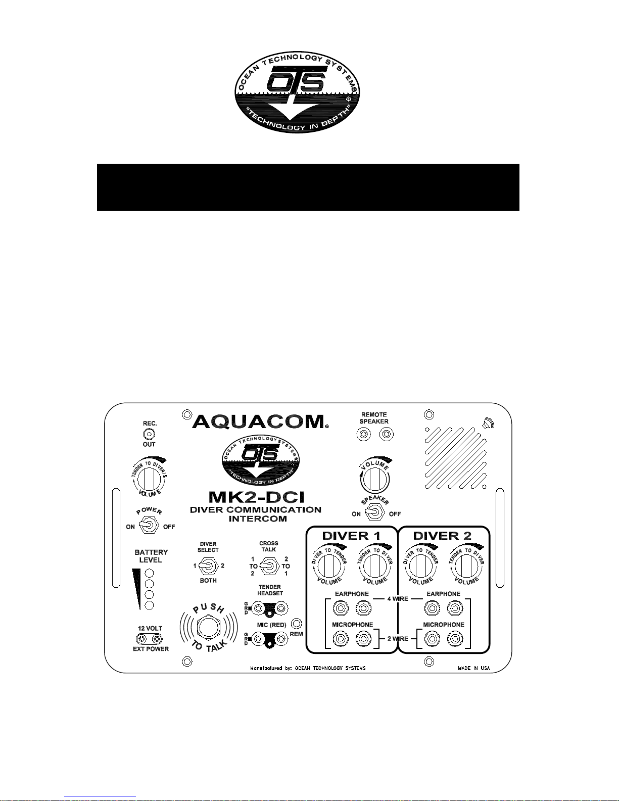
Figure 1. MK2-DCI Two-Diver Air Intercom ......................... 4
Figure 2. Two-Wire Mode ....................................................... 6
Figure 3. Four-Wire Mode ....................................................... 6
Figure 4. Battery Setup ............................................................ 8
Figure 5. Battery PC Board...................................................... 8
ii
Page 4

SECTION 1: INTRODUCTION
Congratulations! You have just purchased the finest, state-of-the-art hard-wire intercom in the world. Your new MK2-DCI Two- or One-Diver Air Intercom represents state-of-the-art technology and innovation—the choice of discriminating divers
throughout the world. Please take the time to read this owner’s manual. With proper
care and use, your Ocean Technology Systems product will provide you with the
ultimate in high-quality communications and reliability.
The MK2-DCI is a compact, self-contained Two- or One-Diver Air Intercom providing clear communications between the operator and diver(s). The MK2-DCI
offers two- or four-wire communications.
This manual will cover specifications, operating instructions, two-wire or fourwire communications, batteries, helpful hints, and warranty information.
These guidelines and illustrations are presented to assist you. If you need additional information, do not hesitate to confer with your local OTS dealer or representative. If you require service, contact Ocean Technology Systems:
Address: 3133 West Harvard Street, Santa Ana, California 92704 USA
Toll-Free: (800) 550-1984
Telephone: (714) 754-7848
Fax: (714) 966-1639
E-mail: ots@otscomm.com
Web: http://www.otscomm.com
1
Page 5

SECTION 2: SPECIFICATIONS
Battery Life: 20 hours continuous use
Battery Type: Two 6-volt lantern batteries, recommended batter-
ies (Eveready Heavy-Duty Alkaline #528 or Duracell
Heavy-Duty Alkaline ID #9150) or an external 12volt source; optional 6-volt rechargeable batteries.
Power Output: 20 watts
Frequency Response: 600 to 12,000 Hz
Cabinet Material: ABS plastic
Front Panel: 1/8” aluminum, chemically treated and coated with
a tough, durable, urethane finish to withstand the
marine environment.
Size: Height: 6-5/8” (16.8 cm)
Width: 16-3/8” (41.6 cm)
Depth: 8-3/8” (21.3 cm)
Weight: 14.0 lbs.
2
Page 6

SECTION 3: OPERATING INSTRUCTIONS
3.1 SYSTEM COMPONENTS
See Figure 1 for a panel description.
1) Record Out: Permits tender to record diving operations (Line level).
2) Volume: Tender-to-diver(s) volume control.
3) Power ON: Turns the power ON or OFF.
4) Battery Level: Color LEDs illuminate to alert tender to conditions of
batteries.
5) Ext. Power: A 12-volt, DC power source can be used.
6) Push-to-talk: Push button used in two-wire mode by tender to talk to
divers.
7) Tender Headset: Tender-worn earphones connect via banana plug connec-
tors.
8) Mic. (RED): Used for hand-held or boom mic. via banana plug con-
nector.
9) Volume: Diver #1 diver-to-tender volume control.
10) Earphone: Diver #1 earphone connection (banana or bare-wire style).
11) Microphone: Diver #1 microphone connection (banana or bare-wire
style).
12) Volume: Diver #1 tender-to-diver volume control.
13) Microphone: Diver #2 microphone connection (banana or bare-wire
style).
14) Earphone: Diver #2 microphone connection (banana or bare-wire
style).
15) Handle: Front panel handle (right & left side).
16) Volume: Diver #2 tender-to-diver volume control.
17) Volume: Diver #2 diver-to-tender volume control.
18) Speaker: Front-panel speaker.
19) Thumb Screw: One of four front panel screws (captive).
20) Speaker: Remote speaker output (speaker level).
21) Volume: Volume control for front panel speaker.
22) Speaker: Switch to turn the front panel speaker ON or OFF.
23) Cross Talk: Switch used to cross-talk Diver 1 to Diver 2 or vice versa.
Tender must hold the switch in the direction of the cross
3
Page 7

4
Figure 1. MK2-DCI Two-Diver Air Intercom
talk. This is a momentary switch.
24) Diver Select: Switch used to select Diver 1, Diver 2, or Both-Divers
communications.
25) REM: This connector is used if a headset/boom microphone
with a PTT switch is used.
3.2 TWO-WIRE MODE
In normal two-wire operations, the two wires within the diver communication
cable are connected to the corresponding binding post (Divers #1 and #2) on the
surface unit (Fig. 2). If a four-wire cable is used, two wires are normally twisted
together for one side of the microphone binding post, and the remaining two wires
twisted together for the other microphone binding post.
This configuration allows the tender to talk to the divers individually or both divers
simultaneously. The diver(s) may also communicate with each other when the
tender engages the cross-talk switch. The divers’ speaker and the surface unit
speaker both function as speaker and microphone. If required, a separate microphone and earphone can be used with the divers’ masks or helmets. If a speaker is
Page 8

5
located in a diving bell or recompression chamber, the MK2-DCI can be used as
the communications link between the divers and the outside. When the system is
used where conditions are noisy, the tender can switch off the speaker and use a
headset and boom microphone. However, when using a headset with a boom microphone, the tender must use a push-to-talk (PTT) button to communicate. Our
headset with a boom microphone has a PTT button located on one side of the
headset. The MK2-DCI also has a PTT. The divers’ communication is the primary
signal. When the tender uses the PTT button, his signal becomes the primary signal. If the diver is trying to say something while the tender is talking, the tender
will not hear the diver until he releases the PTT button.
The divers’ helmets and/or full-face masks typically are wired with the earphones
and microphones tied together. When wired like this, the divers’ earphones and
microphones function together. Bubbles passing by the earphones while the diver
is talking will be picked up via the earphones, causing the communications to be
noisy. When the tender is talking to the diver, his voice is heard not only from the
diver’s earphone, but also from the microphone!
3.3 FOUR-WIRE MODE
The four-wire mode provides continuous open-line communications between the
tender and up to five divers, or any combination of recompression chambers or
diving bells. The four-wire mode will give you optimum performance and intelligibility by the MK2-DCI. Using this method, everyone hears each other simultaneously. Therefore, the earphones, speakers, and microphones must be isolated to
prevent feedback. All earphones are connected in parallel. A four-wire cable is
required for all stations. Two of the wires are used for the microphone and two for
the headset(s) and earphone(s) (Fig. 3). The diver earphones should be connected
to the “EARPHONE” binding post on the surface unit (via the black banana plug
located in the 1 or 2 Diver sections). The banana plug on the tender’s OTS headset
should be connected to the “EARPHONE” banana plug (black; Tender section).
The remote plug on the headset should be connected to the “REM” receptacle
located in the Tender section. The tender’s microphone should be connected to
the red banana plug labeled “MICROPHONE” (Tender’s section). The diver’s
microphone should be connected to the “MICROPHONE” banana plug (red) in
the Diver’s setion of the MK2-DCI. When in the four-wire mode, everyone is online together. It is similar to a telephone conference call.
NOTE: The “Diver Select” must be in the “BOTH” position for four-wire communications in order to hear everyone. A headset with a boom microphone has
to be used by the tender when using the MK2-DCI in the four-wire mode. If you
experience feedback from the headset’s microphone, turn off the front panel
speaker.
Page 9

6
Figure 2. Two-Wire Mode
Figure 3. Four-Wire Mode
Page 10

SECTION 4: BATTERIES
The MK2-DCI Two-Diver Air Intercom can be powered by two 6-volt heavy duty
alkaline batteries, rechargeable 6-volt batteries (Ocean Technology Systems’ model
no. RB-6), or a 12-volt alternate source. To recharge RB-6 batteries, obtain an
RCS-13 universal smart charger from OTS or your local OTS dealer.
The following are options for the desired power source:
1) LANTERN BATTERIES: The MK2-DCI is designed to use two 6-volt springconnector–type batteries. We recommend the use of 6-volt alkaline batteries,
to achieve optimum performance. Eveready or Duracell alkaline batteries provide the best results for most diving operations. You can use standard 6-volt
lantern batteries with spring connectors as well; however, battery life will be
greatly reduced, and you will notice a substantial power drop when transmitting.
INSTALLATION OF 6-VOLT BATTERIES: Locate and loosen the four screws
located on the front panel (Fig. 1, #19). These screws are captive and will not
come off the front panel. Remove front panel from housing. Remove cotter pin
from battery strap (Fig. 4, #3). Remove battery strap from battery housing
(Fig. 4, #2). Insert both 6-volt, spring-type lantern batteries, springs facing
toward battery PC board (Fig. 4, #4). Verify that the batteries are secure on the
bottom of the housing and the backs are being held by the back plate. You will
notice the batteries can be installed with springs in any direction on the PC
board (Fig. 5). After batteries are installed, replace the battery strap and cotter
pin, dress the wires so they are not pinched when you put the front panel back
in place, replace the panel, and tighten the four screws (do not overtighten).
2) 6-VOLT RECHARGEABLE BATTERY (RB-6V): When utilizing the optional
RB-6V sealed lead acid battery, you will attain the maximum performance of a
self-contained battery (two are required).
Note: The batteries you receive may have upgraded specifications from what
is stated in this manual. Due to advancing battery technologies, we continually upgrade our batteries and chargers. Contact OTS or your OTS dealer to
find out the latest available battery and charger.
Install the RB-6V batteries per the instructions found on page 9, “INSTALLATION OF 6-VOLT BATTERIES.”
The RCS-13 universal smart charger is available for rapid charging of RB-6
rechargeable batteries. It closely monitors the batteries’ voltage level to charge
them only as necessary. Power cords compatible with the electrical outlets of
various regions of the world are available for use with the RCS-13.
7
Page 11

8
To recharge the RB-6V batteries, you need
not remove them from the MK2-DCI. Just
connect the RCS-13 universal smart battery charger to the front-panel 12-volt external power jack. Then connect the
charger’s power plug to any 90-260–volt,
60-cycle power outlet. For further instructions and important information about
charging with the RCS-13, refer to the instructions provided with the charger.
IMPORTANT SAFETY NOTE
Before you connect the battery charger to the external power jack, verify
that the installed batteries are rechargeable batteries. We recommend that
rechargeable batteries be used when external power is supplied. The external source should provide a voltage greater than 12 but less than 15
volts. It will recharge the batteries while the system is operating. Never
attempt to recharge
Before powering up the MK2-DCI, always wait at least 20 minutes for
any gasses expelled during charging to dissipate. While charging batteries, avoid smoking, open flames, or striking a match.
3) ALTERNATE POWER SOURCE: The external receptacle (Fig. 1, #5) provides an easy terminal for a marine or automotive 12-volt DC source. The
power source should provide 12 volts and a minimum of 3 amps capacity. The
Figure 4. Battery Setup
Figure 5.
Battery PC Board
Page 12

9
alternate power source connection is also used for charging the battery.
4) LOW-BATTERY LEDs: The four LEDs illuminate one at a time, starting with
the upper LED. Green represents fresh or fully charged batteries. As long as
the power is 11 volts or higher, the top green LED will illuminate. As the
power decreases to approximately 10 volts, the second green LED will illuminate. The top green LED shuts off. When power falls to approximately 9 volts,
the yellow LED will illuminate and the green LED will shut down. When power
reaches approximately 8 volts, the red LED will illuminate and the yellow
LED will shut down. At this point the MK2-DCI will audibly start warning you
of lower seconds. When power falls below 8 volts, the red LED will start blinking and the warning beeps will come every 15 seconds.
At this point the MK2-DCI will audibly start warning you of lower power with
a beeping sound every 30 seconds. When the voltage falls to about 7 volts, the
red LED will start blinking and the warning beeps will come every 30 seconds.
When the voltage falls below 7 volts, the beep occurs every 15 seconds. Below
6 volts the LED blinks quickly for a few seconds, after which the unit shuts off
to save the battery from damage. The warning mode continues until the user
installs fresh batteries, charges the batteries, or connects a 12-volt power source,
or until the power drops enough to shut down the MK2-DCI (see the “LED
Chart”).
COLOR VOLTAGE ON BEEPING
Green 11 volts DC or above Solid None
Green Approximately 10 volts Solid None
Yellow Approximately 9 volts Solid None
Red Approximately 8 volts Solid Every 30 seconds
Approximately 7 volts Blinking Every 30 seconds
Below 7 volts Blinking Every 15 seconds
LED CHART
Page 13

SECTION 5: HELPFUL HINTS
1) Before diving operations begin, check to be sure the microphone, earphones,
and wire connections are secure and operating properly. Ninety percent of all
problems in communications turn out to be a problem with one of the above.
2) When in the four-wire mode, you must use a headset with a boom microphone,
and the Diver Select switch must be in the “BOTH” position. If feedback is
present, switch off the front panel speaker (Fig. 1, #24).
3) Avoid excessive tender-to-diver volume. Most of the time, when there is too
much volume, the diver will hear distortion and ask for more volume!
4) Before diving operations, always check the battery power level, and replace or
recharge the batteries if necessary.
5) Make certain the headphone and remote PTT plugs are securely inserted into
the proper receptacle.
6) When in the four-wire mode and a wire breaks, try setting the system up in the
two-wire communication mode (Fig. 2), and continue diving operations.
7) Secure the MK2-DCI if using the unit on a vessel that is rolling about. Also
strain-relief the umbilical(s) so they will not pull on the MK2-DCI.
8) Ensure the umbilicals are dressed out so as not to trip anyone.
10
Page 14

11
TROUBLESHOOTING FOR MK2-DCI
PROBLEM PROBABLE CAUSE REMEDY
No Power Battery exhausted Replace battery
Battery leads loose Check battery
connectors
Defective ON/OFF Change switch
switch
Board connector not Clean pins
making contact
Open circuit on board Repair or replace board
Power only for a short Defective boot circuit Repair or replace
time when power switch board
is turned on
Defective CPU chip Replace CPU or
replace board
No diver voice Loose connection at Check connector;
ribbon lead connector clean or reconnect
Board connectors Clean pins and
loose reconnect
Defective PCB Replace board
Defective speaker Replace switch
ON/OFF switch
Defective volume Replace control
controls
Defective panel Replace speaker
speaker
Defective pre-amp Replace
chip
Defective relay Replace
PTT logic circuits Repair or replace
defective board
No tender voice Defective board Replace
Defective relay Replace
Page 15

PROBLEM PROBABLE CAUSE REMEDY
Defective pre-amp Replace
chip
Open trace on board Repair trace or
replace board
PTT logic circuits Repair or replace
defective board
Weak battery Charge (if
rechargeable) or replace
Microphone pre-amp Trace signal to find
circuit defective fault and replace
defective part
No record-out function Board connector not Clean pins or replace
making contact defective connector
Defective record amp Trace fault around
record op-amp and
replace faulty part
Replace board
Weak output to divers Power amplifier Replace power
and tender defective amplifier chip
Defective component Trace part and replace
that supports the power
amplifier is defective
Distorted unintelligible Bias supply faulty Check supply and
speech replace defective part
Cannot cross-talk Defective cross-talk Replace cross-talk
divers switch switch
Defective relays Replace relays
CPU defective Replace CPU
Tender-to-diver faulty Defective PTT switch Replace PTT switch
in two-wire mode
Defective relays Replace relays
Defective CPU Replace CPU
12
Page 16

13
Undersea Systems International
dba
Ocean Technology Systems
LIMITED WARRANTY
The MK2-DCI is fully warrantied against defects in materials and workmanship for a period of 1 year from the time
of purchase. Our obligation under this warranty is limited
to the replacing of any part or parts that prove to our satisfaction to have been defective and that have not been misused or carelessly handled. Labor is warrantied for 1 year
from time of purchase. The complete unit and/or part must
be returned to our factory, transportation charges prepaid.
We reserve the right to decline responsibility where repairs
have been made or attempted by other than an Ocean Technology Systems factory-trained service center or properly
trained personnel. In no event shall Ocean Technology Systems be liable for consequential damages.
© Copyright 2001 Ocean Technology Systems
3133 West Harvard Street, Santa Ana, CA 92704, USA
Telephone (714) 754-7848 • Toll-Free (800) 550-1984 • Fax (714) 966-1639
www.oceantechnologysystems.com
You can now register your product online at the OTS Web site. Just visit
http://www.otscomm.com/register1.html.
 Loading...