

OTMT SC4 User Manual And Installation Manual

1
SC4 Bench Lathe
User’s Guide and Installation Manual
Version date: 02-09-11
Please Read This Manual Carefully Before Operating this Machine.
Copyright by Travers Tool Co., Inc., February 2011
PDF created with pdfFactory Pro trial version www.pdffactory.com

2
Table of Contents
IMPORTANT SAFETY INSTRUCTIONS.............................................................................................4
Lathe Features...................................................................................................................................5
Welcome............................................................................................................................................6
User Manual....................................................................................................................................6
Capabilities of the Lathe..................................................................................................................6
Setting up the Lathe..........................................................................................................................7
Electrical Requirements...................................................................................................................7
Lifting the Lathe...............................................................................................................................7
Bench Mounting...............................................................................................................................8
Machine Cleanup.............................................................................................................................8
Operating Controls and Features.....................................................................................................9
Carriage Handwheel........................................................................................................................9
Cross-Feed Handwheel...................................................................................................................9
Compound Handwheel....................................................................................................................9
Carriage Lock Screw......................................................................................................................10
Power Feed (Half-Nut) Lever.........................................................................................................10
X-Y Auto Feed Lever.....................................................................................................................10
Tailstock Handwheel......................................................................................................................11
Tailstock Quill Lock........................................................................................................................11
Tailstock Locking Handle...............................................................................................................11
Tailstock Offset Feature.................................................................................................................11
Electronic Controls.........................................................................................................................12
Control Panel.................................................................................................................................12
Setting the Spindle Speed..............................................................................................................12
Emergency Stop Button.................................................................................................................12
Spindle Disengagement Knob........................................................................................................13
Tooling and Accessories................................................................................................................14
High Speed Steel Cutting Tools.....................................................................................................14
4-Jaw Independent Chuck.............................................................................................................14
Digital Caliper................................................................................................................................14
Center Drills...................................................................................................................................14
Tailstock Chuck and Arbor.............................................................................................................15
Drill Sets........................................................................................................................................16
End Mills........................................................................................................................................16
Eye Protection...............................................................................................................................16
Cutting Fluid...................................................................................................................................17
Initial Safety Checks........................................................................................................................18
Regular Safety Checks – Each Time Machine is Used..................................................................18
Using the 3-Jaw Chuck..................................................................................................................20
Basic Lathe Operations..................................................................................................................22
Stock Preparation..........................................................................................................................22
PDF created with pdfFactory Pro trial version www.pdffactory.com

3
Cutting Tool Selection....................................................................................................................22
Setting the Tool Height..................................................................................................................23
Quick Change Tool Posts..............................................................................................................24
Positioning the Tool.......................................................................................................................24
Rotational Speed Selection............................................................................................................25
Facing a Workpiece.......................................................................................................................25
Cleaning up a Facing Cut...............................................................................................................27
Facing with Power Feed................................................................................................................27
Center Drilling a Workpiece...........................................................................................................29
Drilling a Workpiece.......................................................................................................................30
Turning a Workpiece......................................................................................................................32
Turning with Power Feed...............................................................................................................33
Cutting Short Tapers......................................................................................................................35
Cutting Screw Threads..................................................................................................................37
Setting Up a Gear Train.................................................................................................................37
Thread Cutting Exercise................................................................................................................40
Maintenance....................................................................................................................................43
Periodic Lubrication.......................................................................................................................43
Bearing Race Lubrication...............................................................................................................43
Bare Metal Surfaces......................................................................................................................43
Adjusting the Gibs..........................................................................................................................43
Appendices......................................................................................................................................44
Appendix A – Specifications...........................................................................................................44
Lathe..........................................................................................................................................44
Milling Head Accessory..............................................................................................................44
Appendix B – Parts Diagrams........................................................................................................45
Appendix C – Parts List.................................................................................................................47
Appendix D – Circuit Diagram........................................................................................................49
Appendix E – Packing List.............................................................................................................50
PDF created with pdfFactory Pro trial version www.pdffactory.com

4
IMPORTANT SAFETY INSTRUCTIONS
Common sense and caution are factors which cannot be built into any product. These factors
must be supplied by the operator.
PLEASE REMEMBER:
1. When using electric tools, machines or equipment, basic safety precautions should
always be followed to reduce the risk of fire, electric shock, and personal injury.
2. Keep work area clean. Cluttered areas invite injuries.
3. Consider work area conditions. Do not use machines or power tools in damp, wet or
poorly lit locations. Don not expose equipment to rain, keep work areas well lit. do not
use tools in the presence of flammable gases or liquid.
4. Keep children away; all children should be kept away from the work area.
5. Guard against electric shock. Prevent body contact with grounded surfaces such as
pipes, radiators, ranges and refrigerator enclosures.
6. Stay alert. Never operate a power tool if you are tired.
7. Do not operate the product if under the influence of alcohol or drugs. Read warning labels
on prescriptions to determine if your judgment or reflexes might be impaired.
8. Do not wear loose clothing or jewelry as they can be caught in moving parts.
9. Wear restrictive hair covering to contain long hair.
10. Use eye and ear protection. Always wear.
11. Keep proper footing and balance at all times.
12. Do not reach over or across running machines.
Before operations
1. Be sure the power switch is OFF when not in use and before plugging in.
2. Do not attempt to use inappropriate attachments in an attempt to exceed the tool’s
capacity.
3. Check for damaged parts before using the machine. Any part that appears damaged
should be carefully checked to determine that it will operate properly and perform its
intended function.
4. Check for alignment and binding of all moving parts, broken parts or mounting fixtures
and any other condition that may affect proper operation. Any part that is damaged
should be properly repaired or replaced by a qualified technician.
5. Do not use the machine if any switch does not turn off properly.
Operation
1. Never force the machine or attachment to do the work of a larger industrial machine. It is
designed to do the job better and more safely at the rate for which it was intended.
2. Always unplug the cord by the plug. Never yank the cord out of the wall.
3. Always turn off the machine before unplugging.
PDF created with pdfFactory Pro trial version www.pdffactory.com

5
Lathe Features
PDF created with pdfFactory Pro trial version www.pdffactory.com

6
Welcome
Congratulations on selecting the OTMT SC4
Bench Lathe (SC4). You have chosen a
precision machine tool that can perform a wide
range of complex and precise lathe operations.
With proper maintenance and care, it will
provide many years of service. Should you
have any questions regarding the operation of
your lathe, please contact Travers Technical
Support for assistance.
Technical Support
(1-800-234-9985, press 4)
Fax: 718-661-5637
Email: tech@travers.com
User Manual
The purpose of this manual is to familiarize the
lathe operator with the installation and controls
of the machine and basic lathe procedures. To
become proficient in using the lathe, the
operator should seek in-depth training using
reference books, resources available on the
Internet, training courses at community
technical schools or from an operator already
skilled in the use of a similar lathe.
Capabilities of the Lathe
A precision metal-working lathe is one of the
most useful and productive tools in the
machine shop. The lathe provides the
capability to produce cylindrical and tapered
shapes with very accurate dimensions in a
wide variety of materials such as steel, brass,
aluminum and many plastics. With appropriate
tooling it is even possible to create round,
concave and cubical shapes on the lathe.
The SC4 lathe is equipped with a powerful
1000-watt brushless DC motor with electronic
speed control, providing strong torque at all
speeds, electronic braking and instant direction
reversal for operations such as tapping. The
motor is completely sealed from dirt, dust, oil,
metal chips and other shop contaminants and
is permanently lubricated and maintenancefree.
While the ultimate precision of a finished
workpiece depends on many factors, such as
the material, shape of the cutting tool, proper
adjustment of the lathe and skill of the lathe
operator, dimensions of one-one-thousandth of
an inch (0.001”) or better are possible.
With the provided set of change gears, power
feed rates may be adjusted and a wide range
of both metric and SAE external and internal
threads can accurately be cut. The optional
milling head accessory (Item # 87-116-027)
adds light vertical milling and precision drill
press capabilities to the SC4.
PDF created with pdfFactory Pro trial version www.pdffactory.com

7
Setting up the Lathe
The SC4 lathe should be located in a welllighted and well-ventilated area free from
excessive humidity or moisture that could
cause rusting of the precision metal surfaces
or tooling.
Electrical Requirements
The SC4 lathe configured for U.S. operation
uses standard 120V AC 60-cycle single-phase
power and has a peak current demand of 12
amps. While a 15-amp circuit may be sufficient
for powering the lathe, a 20-amp circuit is
recommended. The circuit must not be shared
with other high-current devices, such as an air
compressor, window air conditioner or coffee
pot, that may be operating, or switch on, while
the lathe is in use. Low current devices, such
as a work lamp, may share the same circuit as
the lathe.
A plug-in power failure emergency light that will
automatically turn on in the event of a power
failure or tripping of an overloaded circuit
breaker is recommended for safety. In the
event that power to the lathe, or workspace
lighting, should be interrupted while the lathe is
in use, the emergency light will enable the
operator to safely turn off the power switch to
the lathe and move away from the lathe until
power is restored. Suitable lights are available
at most hardware and home-supply stores.
Care should be taken to ensure a safe work
area with electrical wiring and grounding
approved by local electrical codes. The lathe
uses a three-prong electrical plug to protect the
operator from risk of shock or electrocution.
The lathe must be plugged into a properly
grounded outlet to ensure safe operation. Do
not attempt to modify the plug to fit a 2-prong
outlet or extension cord by removing the
ground conductor or by using an adaptor.
Doing so may result in shock or electrocution.
If it is necessary to plug the lathe into an
extension cord, the extension cord must have
a properly functioning 3-prong electrical ground
plug and outlet, plugged into a properly
grounded 3-prong wall outlet. The extension
cord must have at least 15 Amps of currentcarrying capacity to avoid overheating the cord,
which could cause a risk of fire. A cord rated
for 20 Amps or more is recommended. In no
case should the length of the extension cord
exceed 20 feet.
Lifting the Lathe
The SC4 lathe weighs approximately 275 lbs.
(125 kg.) and must be mounted on a strong
table or bench capable of supporting 350 lbs.
or more. A shop crane with a nylon lifting strap
or other suitable lifting apparatus should be
used to safely lift the machine onto the table or
bench.
Shop crane (Item # 96-004-166)
Using a shop crane to lift the lathe
Proper lifting techniques (e.g. bend at the
knees, not at the back) should be used to
minimize any risk of personal injury. Consult
the Internet for information on proper lifting
techniques.
PDF created with pdfFactory Pro trial version www.pdffactory.com

8
Bench Mounting
For stability and safe operation the lathe must
be bolted to a sturdy machine stand or
workbench capable of safely supporting at
least 350 lbs. A carpenters or machinists level
should be used to verify that the lathe bed is
level. Large diameter metal fender washers or
shims may be used under mounting feet to
level the lathe. Sufficient clearance must be
provided on the left side of the lathe to allow
the access door to swing open and provide
working room to adjust the gears
Machine Cleanup
The lathe is protected from rust during shipping
by a waxy red grease that must be removed
before putting the machine to use. This is best
done using disposable shop rags and paint
brushes together with a solvent such as
kerosene or WD-40. Avoid solvents such as
paint thinner that may damage the painted
surfaces of the lathe, and highly volatile
solvents such as acetone that present a fire
and inhalation hazard.
Good ventilation must be provided when
solvents are used and care must be taken to
avoid open flames, smoking materials or
electrical sparks that could ignite solvent fumes.
Care should be taken to clean the shipping
grease from all moving parts, including parts
that may be hidden from view, such as
leadscrews under the cross-slide and
compound slide.
PDF created with pdfFactory Pro trial version www.pdffactory.com
9
Operating Controls and Features
Carriage Handwheel
The carriage handwheel moves the carriage
back and forth along the ways. Turning the
handwheel clockwise moves the carriage
towards the tailstock; turning it counterclockwise moves the carriage towards the
headstock.
Carriage Handwheel
When the carriage is moved by power feed,
the carriage handwheel may be disengaged by
pulling it towards the operator. This prevents
the handwheel from rapidly rotating and
causing a potential hazard. To re-engage the
handwheel, press it inwards while slowly
rotating it until the gears engage.
Carriage Handwheel Disengaged
Cross-Feed Handwheel
The cross-feed handwheel (also known as the
cross-slide handwheel or cross-feed) advances
or retracts the carriage across the ways. This
motion may control the depth of a cut for a
turning or boring operation or may advance the
cutting tool across the face of a workpiece in a
facing operation.
Cross-Feed Handwheel
Compound Handwheel
The compound handwheel (also known as the
compound feed) advances or retracts the
toolpost along the angle at which the
compound is set as indicated by the protractor.
The compound handwheel typically is used for
making short tapered cuts, limited by the range
of motion of the compound slide, and for
thread cutting operations.
Both the cross-slide and compound
handwheels have graduated collars that can
be used to measure the movement of the
cutting tool towards or away from the
workpiece. By grasping the graduated dial
while holding the handwheel steady, the
graduated dial can be set to a zero reading to
facilitate making a cut to a specific depth.
Calibrated Handwheel Dial
PDF created with pdfFactory Pro trial version www.pdffactory.com
10
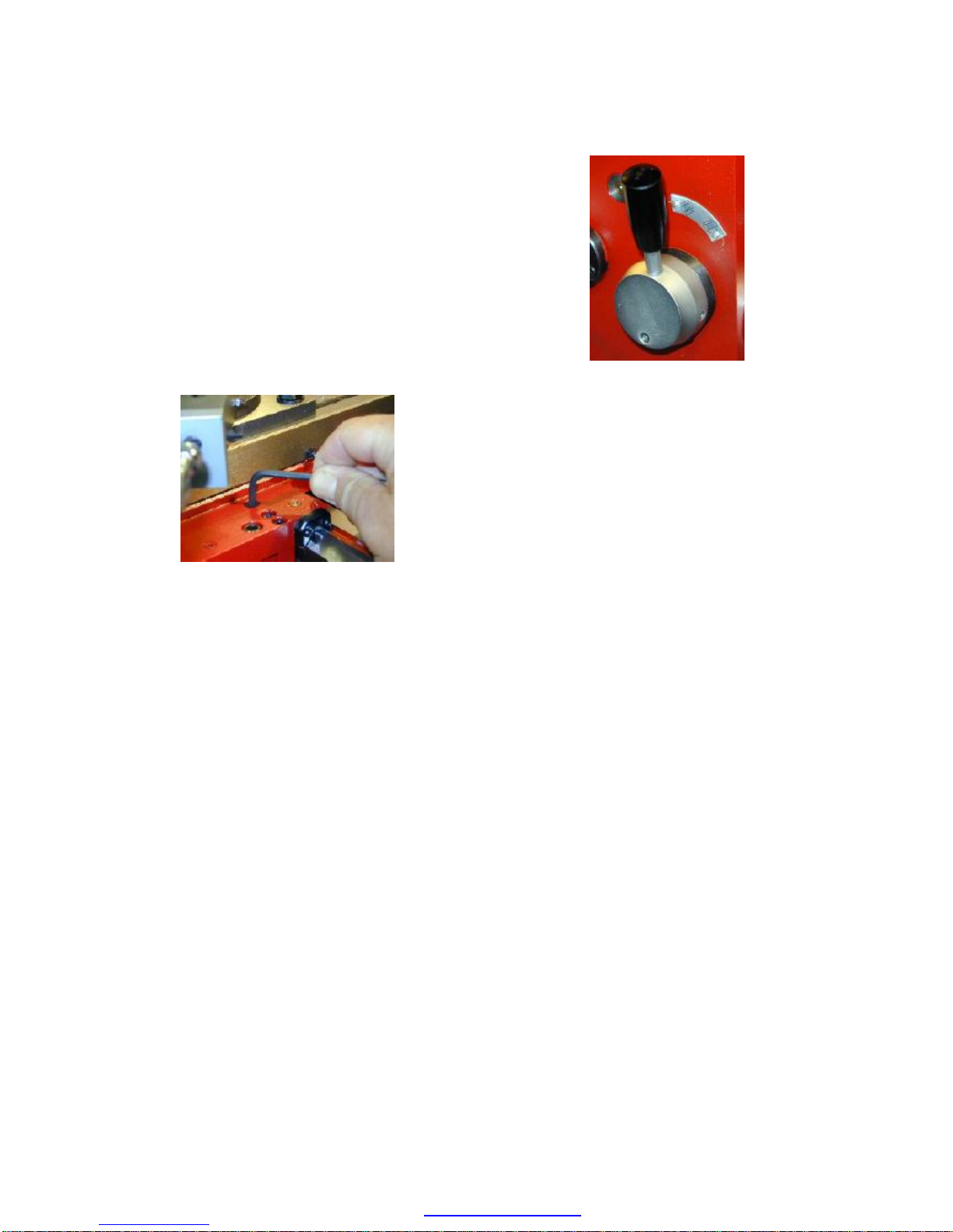
Carriage Lock Screw
For certain operations such as facing, in which
the tool is advanced across the face of the
work by the cross-feed handwheel, it is good
practice to lock the carriage to the ways to
prevent the carriage from moving during the
cut. If the carriage were to move during a
facing cut, the result would be a slightly
concave or convex cone-shape rather than a
perfectly flat surface on the end of the
workpiece.
Locking the carriage
The carriage is locked by turning the carriage
lock screw clockwise using a 5mm hex wrench.
When the locking screw is used for the first
time it may be in the locked position as
shipped from the factory to prevent the
carriage from shifting position during shipment.
Always check to make sure that the locking
screw is unlocked before attempting to move
the carriage with the carriage handwheel or
power feed.
Power Feed (Half-Nut) Lever
The Power Feed Lever, also known as the
Half-Nut Lever, is located on the right side of
the apron at the front of the lathe, next to the
carriage handwheel. It is used to drive the
carriage under power for turning and threading
operations.
Power Feed (Half-Nut) Lever
When turned about 45 degrees to the right, it
clamps a pair of “half-nuts” around the thread
of the lead screw. If the lead screw is engaged
and rotating, the carriage will be moved along
the ways under power from the leadscrew.
Before engaging the Power Feed Lever,
ensure that the carriage is not locked to the
ways by the Carriage Lock Screw.
When the spindle is rotating in the Forward
direction, the carriage is moved towards the
headstock. With the spindle rotating in the
Reverse direction, the carriage moves away
from the headstock. Moving the lever back to
the vertical position disengages the half-nuts
from the leadscrew and stops the motion of the
carriage.
X-Y Auto Feed Lever
Located on the right side of the apron, next to
the Power Feed Lever, the X-Y Auto Feed
Lever controls the motion of the carriage when
used with the optional milling head accessory,
but can also be used for lathe operations.
When using the X-Y Auto Feed Lever, the
Power Feed lever must be disengaged.
PDF created with pdfFactory Pro trial version www.pdffactory.com
11
X-Y Auto Feed Lever
In the lower position, the X-Y Auto Feed lever
moves the carriage along the ways, much like
the Power Feed lever, but at a slower speed.
This feature is useful for making fine finishing
cuts using power feed.
In the upper position it functions as a power
cross-feed control and moves the cross slide
away from the operator towards the back of the
lathe. When the motor is reversed, the power
cross feed moves the cross slide towards the
operator. In the center, “0” or neutral position,
the feed is disengaged.
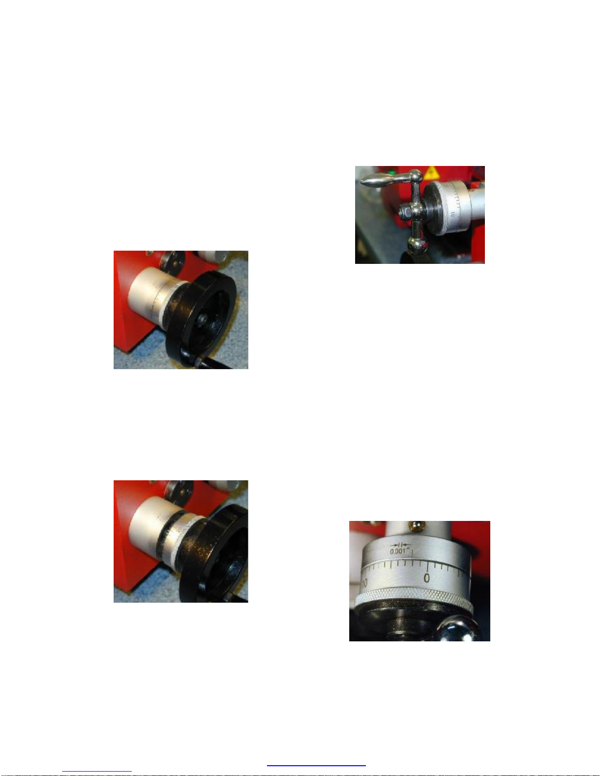
Tailstock Handwheel
Rotating the tailstock handwheel moves the
tailstock quill (also known as the tailstock ram)
in and out of the tailstock. This feature is used
during drilling operations and when a center is
used in the tailstock to support long stock.
Tailstock Quill Lock
When the tailstock is used in stationary
operations, as when supporting the end of long
stock, the quill may be locked in place using
the tailstock quill lock. A quarter turn of the
handle is sufficient to lock or unlock the quill.
Tailstock Locking Handle
The tailstock locking handle on the rear of the
tailstock locks the tailstock at any location
along the ways. The tailstock is locked by
pulling the lever towards the operator and
released by pushing the lever away from the
operator. If necessary, the clamping action
may be adjusted by removing the tailstock from
the end of the lathe ways and adjusting the
locking nut on the underside of the tailstock.
A stop screw located between the ways at the
right end of the lathe prevents the tailstock
from falling off the end of the lathe. This screw
must be removed before sliding the tailstock off
the end of the ways for adjustment.
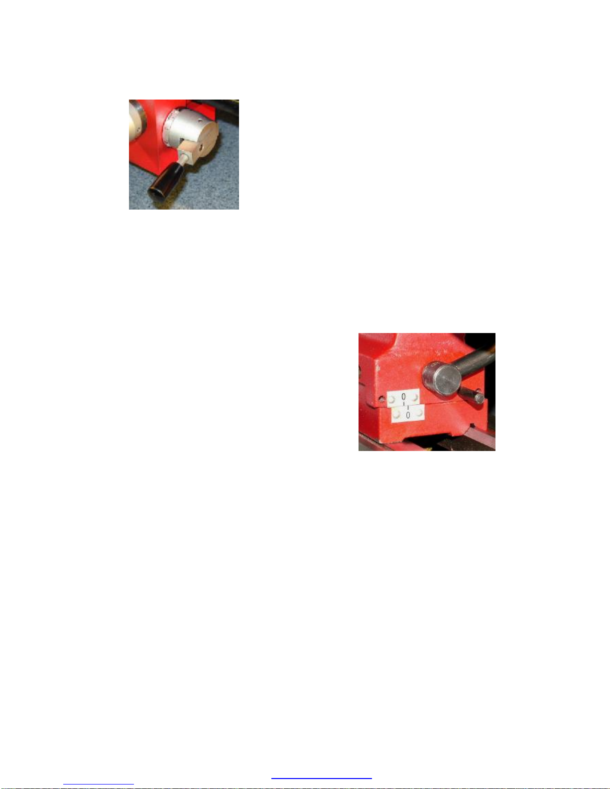
Tailstock Offset Feature
To turn long tapers on a workpiece mounted
between centers, the tailstock may be offset
horizontally from the lathe centerline. To offset
the tailstock, loosen the two small setscrews
below the cam lever on the right side of the
tailstock, then loosen the two setscrews on the
front and back sides of the tailstock.
Tailstock Offset Indicator
The two screws on the front and back of the
tailstock work in opposition to each other to
offset the tailstock; as one screw is tightened
the other must be loosened by a corresponding
amount. The amount of offset may be gauged
by observing the offset indicator guide on the
right end of the tailstock.
After completing the taper operation, the
tailstock is restored to its normal position at the
horizontal centerline. Accurate alignment using
a test bar and dial indicator is recommended.
PDF created with pdfFactory Pro trial version www.pdffactory.com

12
Electronic Controls
The main power switch for the lathe is the red
rocker switch located on the control panel. A
green pilot lamp illuminates when the power is
on. A fuse holder above the pilot lamp contains
a replaceable 20 Amp fuse to protect the lathe
from electrical overloads.
Control Panel
Control Panel
A soft-touch panel of buttons controls the lathe
spindle speed and direction:
é - Increase spindle RPM speed
ê - decrease spindle RPM speed
Start – start the spindle motor
P – set spindle to forward rotational
direction
Q – set spindle to reverse rotational
direction
Stop – stop the spindle motor
Setting the Spindle Speed
To start the spindle rotation, press the Start
button. The current spindle rotational speed
and direction (FOR or REV) are displayed on
the digital display.
Spindle-speed tachometer
When the lathe is powered on or the
Emergency Stop button is reset, the display
will momentarily display 8888, then will display
0000.
To increase the speed of spindle rotation,
depress and hold down the é button. To
decrease spindle speed, depress and hold
down the ê button. Small incremental changes
to the spindle speed may be made by
momentarily pressing the buttons. To stop the
spindle rotation, press the Stop button.
The first time that the Start button is pressed
after turning on the power to the lathe, of after
resetting the Emergency Stop button, the
spindle will begin turning at its slowest speed,
about 100 RPM.
When the operating speed is adjusted to a
higher RPM, the new speed is saved when the
Stop button is pressed. When Start is pressed
again, the lathe will resume operating at the
saved speed. The saved speed is cleared
when the lathe is powered off or the
Emergency Stop button is pressed.
Emergency Stop Button
Located below the Start button, the red
Emergency Stop button is used to quickly
stop the spindle in the event of an emergency,
PDF created with pdfFactory Pro trial version www.pdffactory.com

13
such as a workpiece working loose from the
chuck.
Emergency Stop button
Pressing the Emergency Stop button firmly
with the heel of the hand will bring the spindle
to a stop and keep the lathe from restarting
until the Emergency Stop button is reset by
rotating the knurled rim of the button in a
clockwise direction.
Pressing the Start button, or any other control
on the panel, will have no effect until the
Emergency Stop button is reset. When the
Emergency Stop button is reset, the spindle
speed will also be reset to the minimum speed
of about 100 RPM.
Spindle Disengagement Knob
The large silver knob to the right of the
Emergency Stop button engages and
disengages the spindle from the motor drive
while still allowing the leadscrew to turn and
move the carriage under power from the gear
train.
Spindle Disengagement Knob
When performing milling operations using the
milling head accessory (Item # 87-116-027) the
spindle should be disengaged for safety so that
the rotating chuck does not pose a hazard.
With the lathe stopped, turn the knob to the
right about ¼ turn to disengage the spindle. To
re-engage it, rotate the knob to the left while
also turning the chuck by hand to allow the
gears inside the head to mesh. The knob
should not be moved while the motor is
running.
PDF created with pdfFactory Pro trial version www.pdffactory.com
14
Tooling and Accessories
Operation of the lathe requires certain basic
necessities such as cutting tools. Optional
accessories such as a 4-jaw chuck and milling
head extend the capabilities of the lathe to
perform advanced types of work. Safety gear,
such as safety glasses and eye shields help to
protect the lathe operator.
This section describes some useful
accessories and tooling for the SC4 lathe.
High Speed Steel Cutting Tools
For the home machinist and light industrial
user of the lathe, High Speed Steel (HSS)
cutting tools are used for most cutting
operations. Along with finished versions, these
tools can be purchased as blanks and ground
to the desired cutting shape using a bench
grinder.
Set of HSS cutting bits
Item # 22-501-102
Aside from low cost, the main benefit of HSS
tools is that specialized tool shapes can be
ground as needed for operations such as
chamfering, material cut-off and boring.
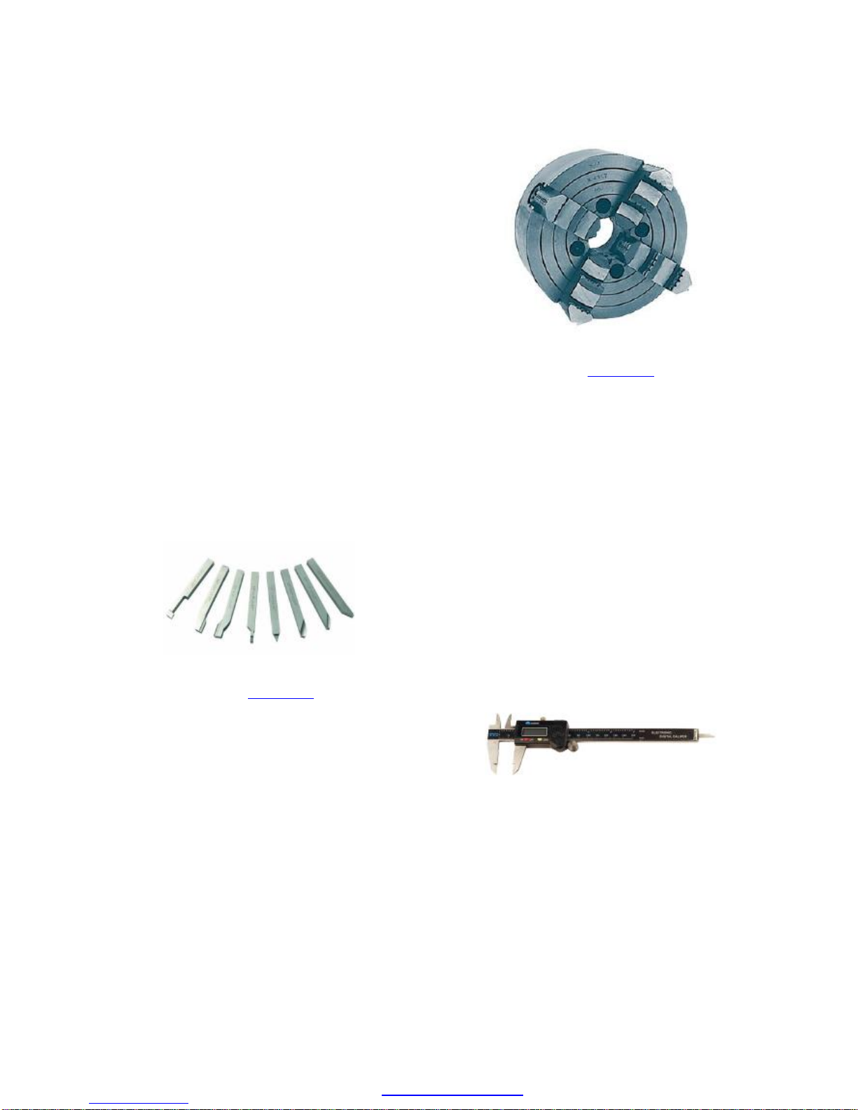
4-Jaw Independent Chuck
A 4-jaw chuck can hold stock with a square or
rectangular cross-section in addition to round
and octagonal stock. Unlike the standard 3-jaw
chuck, in which all of the jaws move together,
on the 4-jaw chuck the jaws adjust
independently, enabling them to clamp
irregularly-shaped stock.
4-Jaw Chuck
Item # 87-116-026
Adjusting the jaws individually makes it
possible to center a round workpiece, or a
reference point on an irregular workpiece, with
great precision. This feature is useful when a
workpiece has features on opposite ends that
must be machined on exactly the same axis.
Offsetting the workpiece also makes it possible
to drill off-center holes and to turn cam lobes.
Digital Caliper
Digital calipers are convenient measuring
tools for many lathe operations. They measure
outside and inside diameters as well as hole
depths to a resolution of 0.0005”. They switch
instantly between metric and inch units, so you
work in either format.
Digital Caliper
Item # 57-016-060
Center Drills
Center drills, also known as a drill &
countersink, are short and stiff and therefore
do not flex.
PDF created with pdfFactory Pro trial version www.pdffactory.com

15
Standard-length drills may flex and wander a
small amount when they first start to penetrate
the surface of the work. The flexing may cause
the starting point to be off-center and therefore
the drilled hole may be off-center and not
perfectly parallel to the axis of the workpiece.
Therefore, it recommended always to use a
center drill to start a drilled hole
Center Drill
Center drills are available in many sizes and
made of various materials, much like drill bits.
For work on the SC4, a set of 5 HSS center
drills, #1 through #5 in size, will meet most of
the needs the operator is likely to encounter.
Set of five Center Drills
Item # 01-095-000
Tailstock Chuck and Arbor
For most drilling operations, the drill bit is held
in a Jacobs-type chuck mounted in the
tailstock by means of a #2 Morse Taper arbor.
Jacobs-style chuck
Item # 63-100-004
Since the chuck and the arbor are purchased
separately, care must be taken that the front
taper of the arbor that mates with the chuck is
the proper size for the chuck.
Chucks for use on a lathe usually have a
female Jacobs Taper, so an arbor is needed
with a #2 Morse Taper on one end and a
Jacobs Taper matching the chuck taper on the
other end.
Arbor for tailstock chuck
Item # 63-004-821
Arbors, such as the one in the photograph,
often have a flat tang at the end of the Morse
Taper, used to drive the arbor in some types of
machinery. For use in the SC4 tailstock, the
tang needs to be cut off using a hacksaw,
metal-cutting bandsaw or abrasive cutoff wheel.
Part of the Morse Taper may also need to be
cut off in order for the arbor to fit properly in the
tailstock bore.
The chuck generally is permanently mounted
to the arbor. To do this, first wipe the JT end of
the arbor and the corresponding JT taper in the
end of the chuck with a clean shop rag to
remove any oil, grease, chips or grit. It is
important that both mating surfaces be free
from any contamination to ensure a tight,
secure fit. Insert the JT taper end loosely into
the chuck taper, then rap the opposite end of
the arbor firmly on a board to drive the tapered
PDF created with pdfFactory Pro trial version www.pdffactory.com
 Loading...