

Page 1
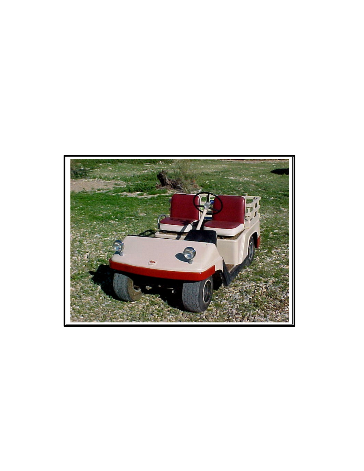
OTIS S-71 GOLF CART
TECHNICAL INFORMATION
Jim Kaness
Revised 4/10/2005
Page 2

2 Page
ACKNOWLEDGEMENTS
The following people have generously provided information to me:
Stephen Showers
Corporate Archivist
Otis Elevator Company
Five Farm Springs Road
Farmington, CT 06032
860-676-5577
Mark Eyestone
Westcoaster Info Center
2306 Crystal Way
Crystal Lake, IL 60012-2221
815-455-2179
AUTHOR’S NOTE
This manual was written without the knowledge, consent, or participation of the Otis
Elevator Company, and it does NOT have their endorsement. This manual is my own
work on my own initiative and the responsibility for its content is mine alone.
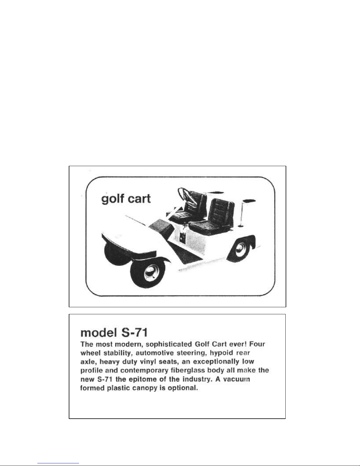
No official Otis S-71 technical or maintenance manual has been located. Except for the
sales brochure excerpt on page 3, the text, drawings, and photographs in this document
are my own work from my own reverse engineering done on my own S-71, and
comparison with other S-71’s available for inspection. Despite 40-odd years of
electronics engineering, technician work, technical writing, and “jack of all trades” it is
still possible for me to err. I reserve the right to update and correct this document as new
information becomes available. Comments, suggestions, and corrections are welcomed.
© 2005 by Jim Kaness
Jim Kaness
4267 Varsity Street
Ventura, CA 93003-3803
805-644-3237
Page 3
3 Page
OTIS S-71 HISTORY
The Otis S-71 golf cart was produced between 1970 and 1976 by Westcoaster, a
subsidiary of Otis Elevator Company. In 1970 Otis Elevator Company acquired West
Coast Machinery Company of Stockton, CA (renamed Westcoaster Company) who
manufactured a full line of electric and gasoline powered vehicles for use off the public
roads- on airports, factories, farms and ranches and golf courses. In 1976 Otis sold the
Westcoaster / Otis product line to EVA-Chloride, who then was engaged in development
of electric vehicles for highway use. In 2005 many of these S-71 golf carts are still in use.
EXCERPT FROM WESTCOASTER BROCHURE “full line” [1]
(Undated, early 1970’s)
Page 4
4 Page
Brake
Assembly
Shaft to
Differential
DC MOTOR
1
OTIS S-71 GENERAL INFORMATION
INTRODUCTION
The Otis S-71 Golf Cart has a fiberglass body on a tubular steel frame, and uses six 6-volt
batteries to power a GE 36-volt series (the field and armature are connected in series) DC
motor. Speed is controlled by adding or removing resistance in series with the motor
voltage. The S-71 provides four speeds forward and reverse. Reverse is accomplished by
reversing connections to the motor armature. The S-71 weighs 740 pounds without
batteries [1] and about 1100 pounds with batteries. Top speed is 12 miles per hour [1].
SERIAL NUMBER
If the S-71 was ever given a serial number I have found no mention of it, or where it
might have been placed.
OTIS S-71 ELECTRICAL
MOTOR
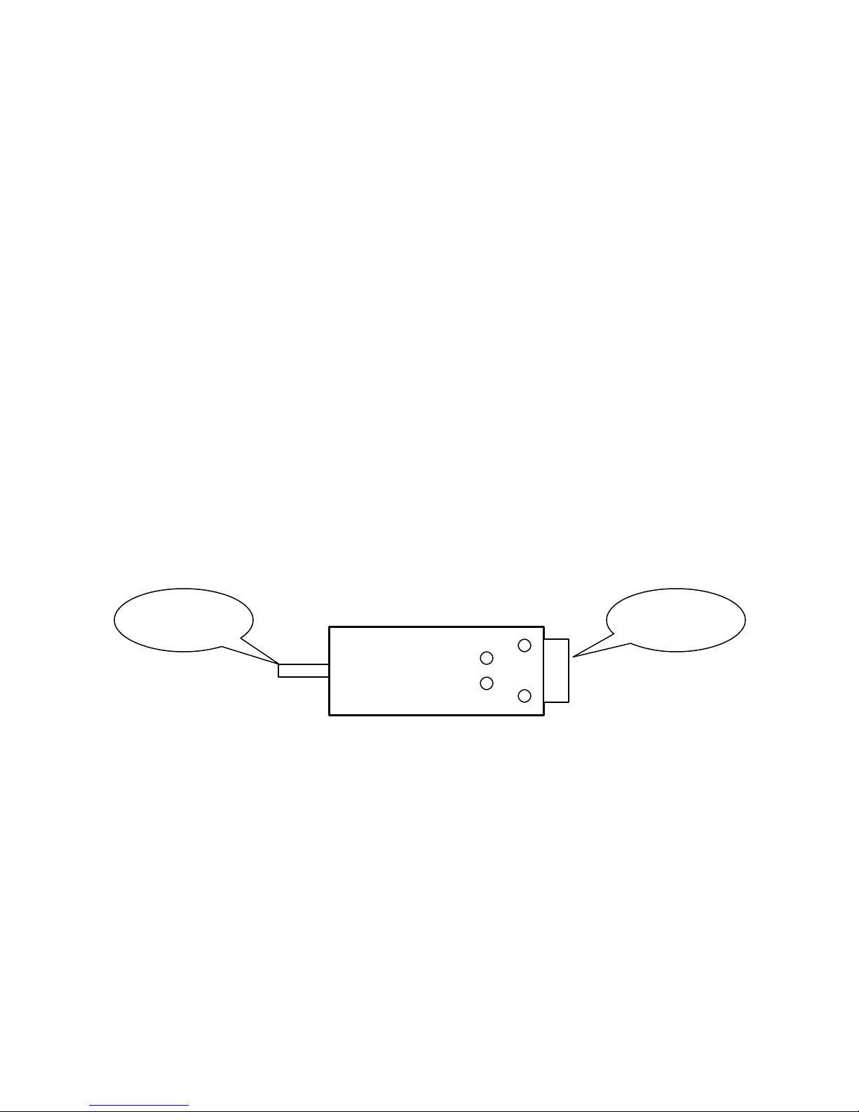
The motor is a General Electric DC Motor, Model 5BC48JB517B rated on the nameplate
for 55-amperes at 36-volts DC. The nominal shaft horsepower rating is 2.0. The motor
terminals are not labeled- I have arbitrarily labeled them 1 through 4 for correspondence
with the diagrams on the following pages. Terminals 1 and 2 go to the field winding.
Terminals 3 and 4 go through brushes to the armature. Brushes are accessible by
removing the rubber plugs next to the terminals.
(Top View)
Most electric motors have the field and armature connected in parallel. When motors are
used for propulsion the field and armature are usually connected in series as this provides
maximum torque at low speed. However a series-connected motor MUST always have a
load on it or its speed may rise to an unsafe value [2]. This will not be a problem here
unless the motor is removed from the S-71 for bench testing.
DIRECTION CONTROL AND INTERLOCK
The Forward / Reverse lever directly operates the high-current DC polarity reversing
switch. To prevent arcing, a microswitch is activated when the lever is in the full
“Forward” or “Reverse” position. These “normally-open” switches close ro allow the
solenoids to operate ONLY when the lever is in the full “Forward” or “Reverse” position.
3
2
4
Page 5

5 Page
SPEED CONTROL
The accelerator pedal operates a pushrod connected to a series of switches inside the
enclosed box on which the solenoids are mounted. As the accelerator is pressed down,
power is applied to the motor through two solenoids, and through resistors (they look like
coils of heavy wire) mounted under the motor. As the accelerator pedal is pressed further
other solenoids reduce the amount of resistance in the circuit. Five solenoids and two
resistors (one with a tap) offer four speeds. This approach has been used in electric street
railways for over a century [3].
Solenoids LT and LB together in series are used to apply or remove power from the
motor. The S-71 uses these two solenoids (LT and LB) with their contacts in series,
apparently to guarantee that power can be removed from the motor in the event the
contacts on one of the solenoids should weld themselves closed. The other three
solenoids (RT, RM, and RB) are used to short out various parts of the resistance for speed
control.
The accelerator, as it is pressed, offers OFF and positions sequentially labeled (by me) A
(slowest), B, C, and D (fastest). With any one of the motor wires disconnected, and key
ON, you can hear the solenoids turn ON as the accelerator is depressed through its range.
The pushrod between the accelerator pedal and the switches can be adjusted in length so
that, at rest, NO switches are engaged, and so just before the accelerator bottoms on the
floorboard ALL switches are engaged.
The five solenoids are basically automotive starter solenoids with all terminals isolated
from the metal case. The solenoid coils are rated at 12 VDC and show a measured DC
resistance of 12 to 14 ohms. In my S-71 they are each operated on 18 VDC.
NOTE: THE S-71 MOTOR USES UP TO 55 AMPERES. FOR
SATISFACTORY OPERATION IT IS VERY IMPORTANT THAT ALL
CONNECTIONS TO THE MOTOR, BATTERIES, RESISTORS, AND
REVERSING SWITCH BE CLEAN AND TIGHT.
LT, Left Top A, B ,C ,D
LB, Left Bottom A, B, C ,D
RT, Right Top B, C, D
RM, Right Middle C, D
RB, Right Bottom D
Solenoid ON Accelerator Position
Page 6
6 Page
REVER
SING
HIGH CURRENT SCHEMATIC
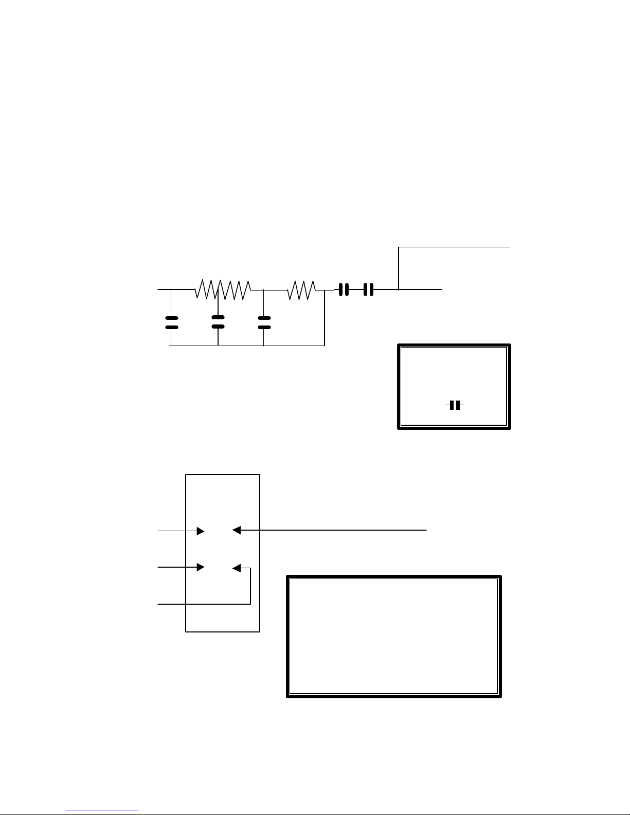
This schematic shows the high-current connections between the batteries and the motor.
MOTOR 1 and MOTOR 2 are the field winding. MOTOR 3 and MOTOR 4 are the
armature winding.
The Forward – Reverse switch swaps connections to the armature winding.
NOTE: The resistors shown are a fraction of an Ohm each and will measure zero Ohms
with the usual bench multimeter.
MOTOR 2
MOTOR 3
MOTOR 4
MOTOR 1
SWITCH
LT LB
RT RM RB
FORWARD
MOTOR 1 TO MOTOR 3,
AND MOTOR 4 TO BATTERY NEGATIVE
REVERSE
MOTOR 1 TO MOTOR 4,
AND MOTOR 3 TO BATTERY NEGATIVE
Red, From Internal Charger
Positive Output
36V BATTERY
POSITIVE
SOLENOID HIGH
CURRENT
CONTACTS ARE
SHOWN AS
36V BATTERY
NEGATIVE
Page 7
7 Page
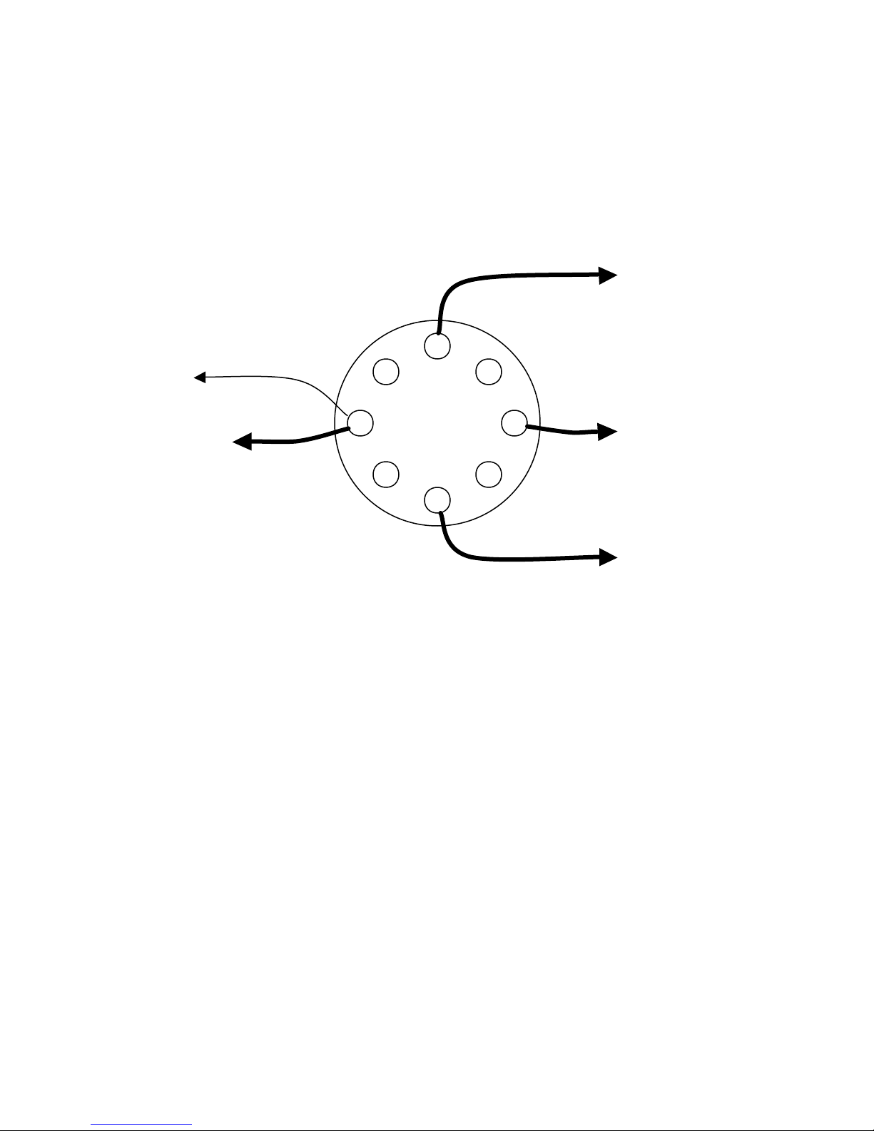
REVERSING SWITCH CONNECTIONS
Viewed from passenger side with control panel pulled forward. The MOTOR 4
connection is at the top. The four unused bolt connections are only there to help the
switch contacts slide smoothly over them to the intended connections.
BATTERY NEGATIVE TO
SOLENOID CONTROL
CIRCUIT (low current schematic)
BATTERY
NEGATIVE
36 VOLTS
MOTOR 4
MOTOR 1
MOTOR 3
Page 8
8 Page
Switch
ACCELERATOR
Two Micro
Key
Switch
20A Inline
20A Fuse on
20A
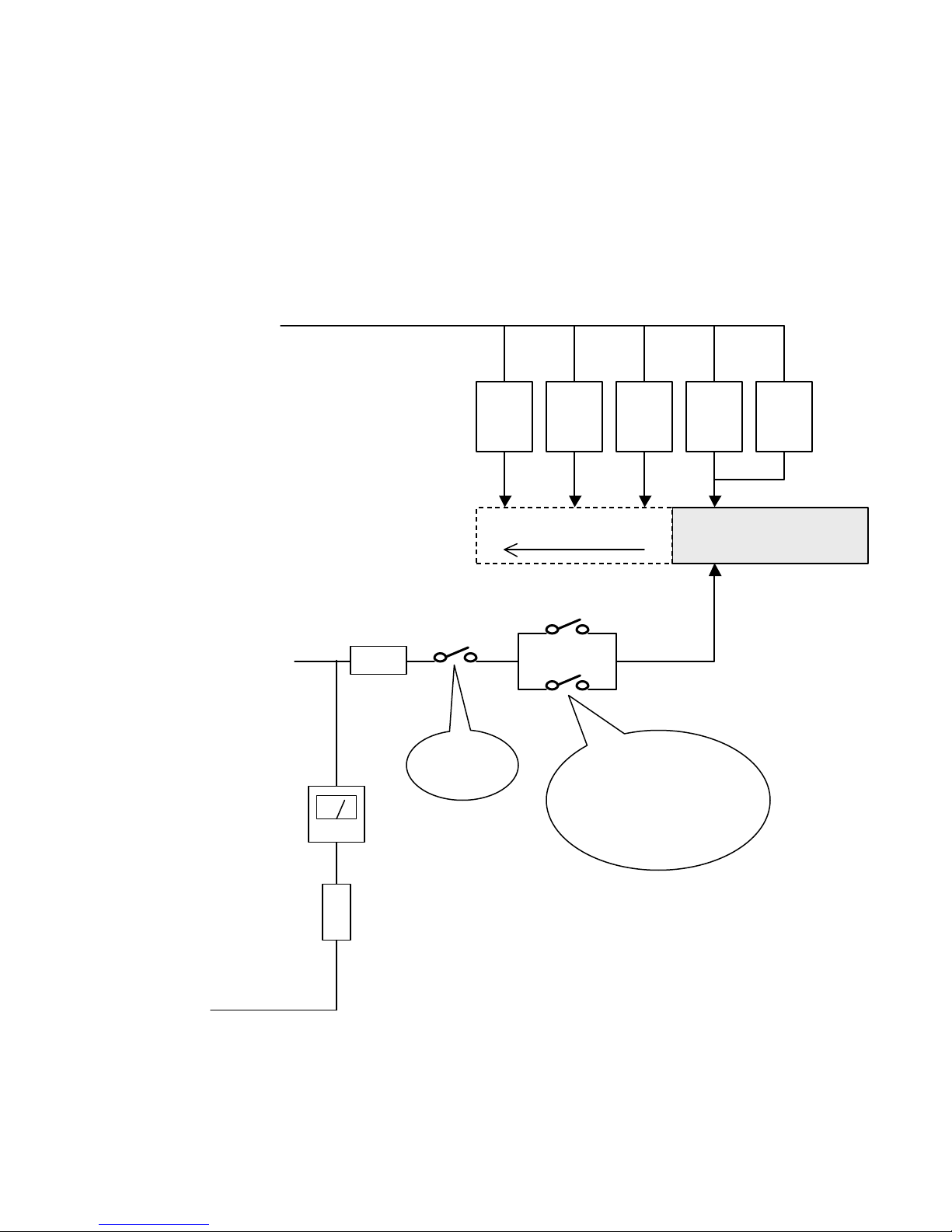
LOW CURRENT SCHEMATIC
This schematic is for the low-current wiring, showing the solenoid coils, switches, and
fuses. The accelerator switch progressively connects more solenoids as the pedal is
pressed down. With the accelerator resting, none of the solenoids is energized. The
drawing shows the switch having energized LB and LT, for the slowest of the four
speeds.
PLUS 18 VOLTS
From center of
36V battery bank
MINUS 18 VOLTS
AND
MINUS 36 VOLTS
From Fwd -Rev
Meter
RB
(faster speed)
Fuse
Switches on Fwd-
Rev Switch
Assembly
LT LB RT RM
SWITCH
Brown, From Internal
Charger Rectifier
Negative Output
Fwd-Rev Switch
Assembly
Page 9

9 Page
OTIS S-71 BATTERIES
BATTERY SPECIFICATIONS
My S-71 uses six 6-volt Trojan batteries, model T-105, rated at 185 ampere-hours for 5
hours. Each measures 7 1/8” wide by 10 3/8” long by 10 7/8” high. The two 5/16 -18
threaded post connections are at diagonal corners. Other high-quality deep-cycle Golf
Cart batteries may be used.
Each T-105 weighs 62 pounds. Use a battery-lifting strap rated for this weight when
removing or installing batteries.
TROJAN BATTERY DA TE CODES
The Trojan date code is a letter-number combination stamped on the negative post. The
code is MY, with the Month being A = January, B = February, etc. The Year is a single
digit such that 3 = 2003, 4 = 2004, etc. Thus A3 indicates January 2003.
WARNING: WHILE 6 OR 36 VOLTS WILL NOT PRESENT A SHOCK
HAZARD, THE HIGH AMPERAGE AVAILABLE FROM THESE
BATTERIES CAN WELD JEWELRY OR TOOLS THAT MAY
ACCIDENTALLY SHORT ONE OR MORE OF THESE BATTERIES.
TO ENSURE YOUR SAFETY, REMOVE RINGS AND WATCHES
FROM HANDS AND ARMS, AND WRAP ALL TOOL HANDLES
WITH TAPE.
WARNING: THESE BATTERIES CONTAIN SULFURIC ACID. IF
THIS ACID CONTACTS SKIN, EYES, OR OTHER BODY PARTS
IMMEDIATELY FLUSH WITH LOTS OF WATER.
BATTERY MAINTENANCE
Periodically check the fluid level in the batteries- in all 18 cells. Hot weather and the
battery charging process will normally cause the batteries to lose water. Remove the caps
and verify that the fluid level is above the lead plates. If it is not, slowly add DISTILLED
water until it is over the plates. DO NOT USE TAP WATER, as the impurities in it will
shorten the life of the batteries.
Periodically check and, if any corrosion is observed, clean the battery terminals.
Corrosion may be neutralized using a solution of baking soda dissolved in tap water. Pour
the solution over the corrosion and use an old toothbrush to brush away the corrosion.
Page 10
10 Page
+36V to LB
EXTERNAL CHARGER INPUT
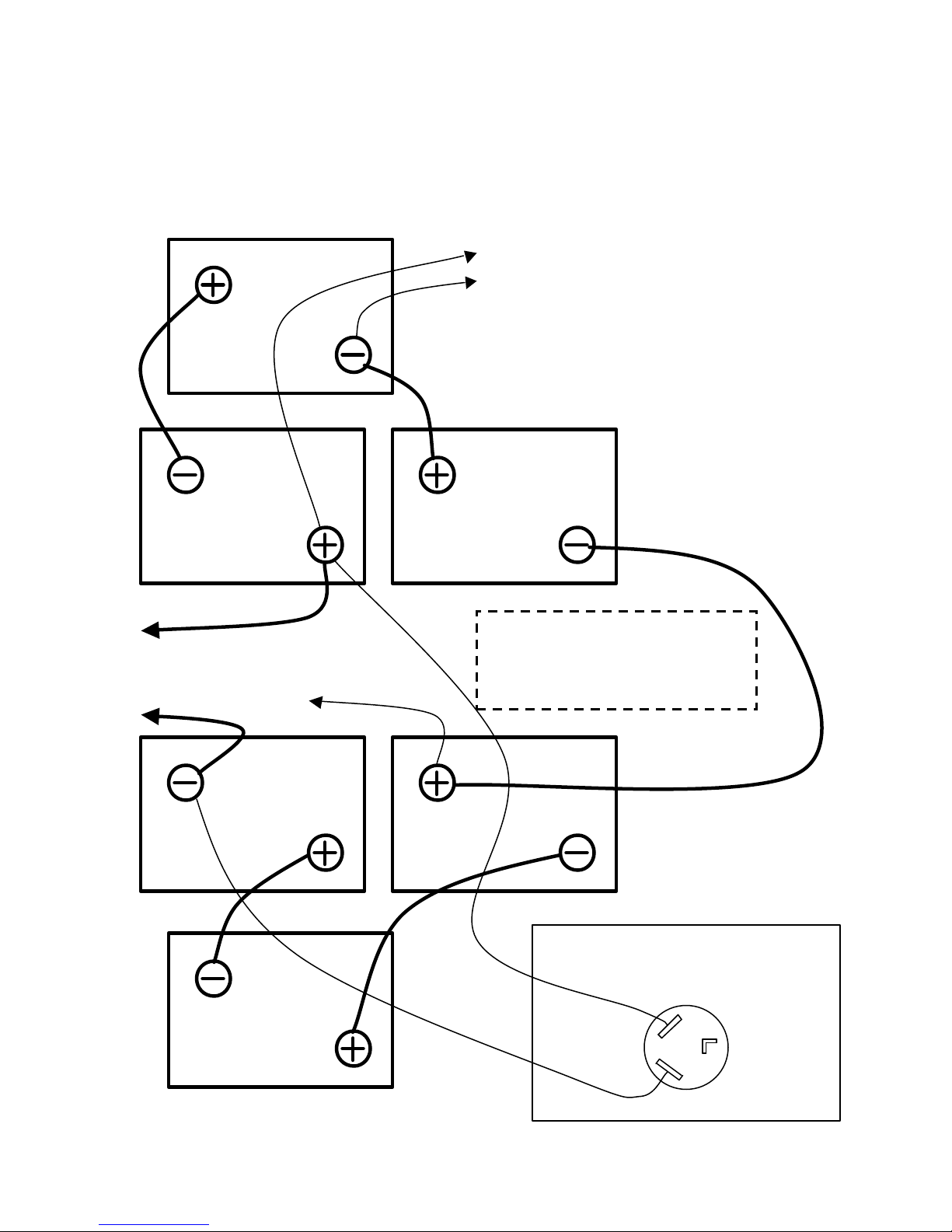
BATTERY LAYOUT AND WIRING
View looking down on the batteries with the seat raised. Top of the page is the passenger
side of the S-71. Left side of the page is toward the front of the S-71.
-36V to FwdRev Switch
+18V to All Solenoids
12V to Lights
GE 36-VOLT
SERIES MOTOR
Viewed From Front
Page 11
11 Page
120
Red, Positive, to LB
Brown, Negative
, to 20A Fuse and Ammeter
Red Red Black
White
Timer
Transformer
Ground to Chassis
BUILT-IN CHARGER
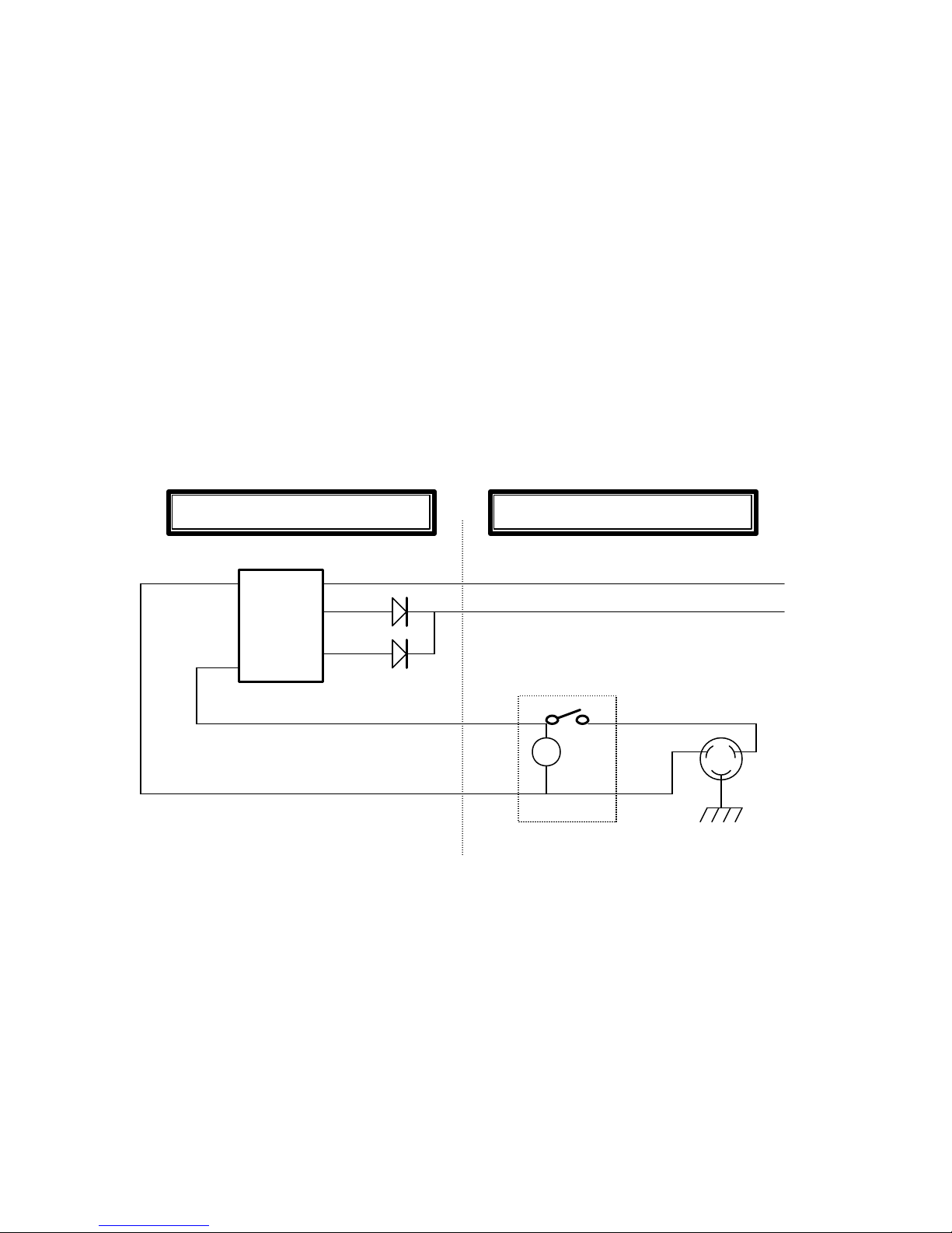
The Otis S-71 originally came with a built-in battery charger. In 2005 most of these are
not functioning and an external charger must be used. In my S-71 the transformer
apparently has an internal short. The transformer and rectifiers are under the front “hood”
behind the dash. The 20-ampere ammeter, timer, and AC power cord connector are on the
operator control panel between the seats. Behind this panel, located on the Fwd-Rev
Switch Assembly, is a 20-ampere fuse between the charger output and the batteries.
The built-in charger uses a transformer and two diodes (my S-71 has two silicon diodes)
in a standard full-wave rectifier circuit. The timer operates off the AC input and allows
charging for the desired number of hours to prevent overcharging. The ammeter confirms
that charging is taking place. The transformer and diodes may be accessed by removing
the glove box in the dash. The glove box mounts with two bolts and tapped L-brackets
that grip behind the dash. To remove, unscrew the two bolts about 8-turns each. It should
then be possible to wiggle the glove box free of the dash. The transformer and diodes are
just inside and to the left.
115
110
The recessed male AC power connector on the S-71 is a type no longer made in 2005. I
made a mating female connector from an L5 -15R female connector by sawing the plastic
connector body to lengthen the arc of the opening for the ground terminal.
Mounted on Control Panel Mounted Behind Dash
Page 12
12 Page
ADDED ACCESSORIES
The Otis S-71 did not originally come with the following accessories. Various owners
have added them to my S-71.
EXTERNAL CHARGER INPUT (added)
The external-charger input is wired directly to the 36-volt connections to the battery
bank. The char ger connector is a standard 30-ampere female connector used for 240VAC
electric clothes dryers. The ground terminal is not used. Any commercial 36-volt charger
may be used for charging the batteries. Mine is a Club-Car model 10470 “Solid State
Fully Automatic” charger.
LIGHTS (added)
The front and rear lights use 12-volts from two of the 6-volt batteries as shown. This
wiring has a 5-ampere fuse for safety. An SPST toggle switch on the dash controls the
lights.
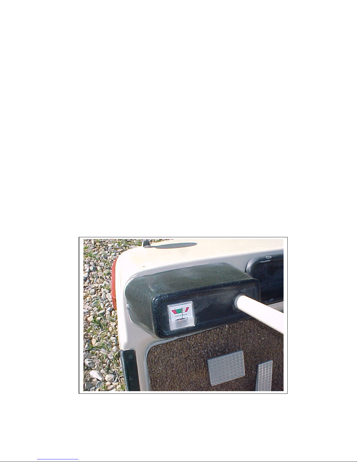
BATTERY STATE OF CHARGE METER (added)
This expanded voltmeter is widely available (in 2005) at golf cart shops for about $30.
This “fuel gauge” is connected to the positive 36-volt battery post. The negative lead
goes to the key switch so the meter only works when the key is ON. A 5-ampere fuse in
the negative lead protects the wiring.
Page 13
13 Page
BRAKE
MOTOR BRUSH
OTIS S-71 MECHANICAL
WHEELS AND TIRES
The S-71 uses 18 x 8.50 – 8 standard golf cart tires widely available in many tread
designs. I am using 8-PSI tire pressure for a smooth ride on gravel roads. The Otis is
unique in using a five-lug rim. The current standard golf cart rim mounts with only four
lugs.
BRAKING
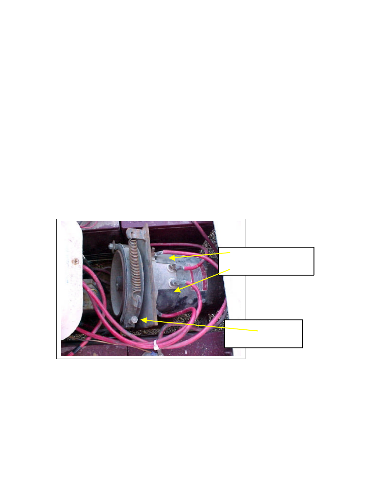
The brake pedal operates a single brake shoe that is pulled against a drum attached (using
a key and an Allen screw) to the forward-end of the motor shaft. The brake pedal is
attached to a flexible cable, the other end of which pulls on the shoe through a spring.
Pushing the brake pedal further engages a pawl that holds the brake ON as a parking
brake. The brake pedal is also interlocked with the accelerator pedal. Simply pushing on
the accelerator pedal will release the parking brake. An adjusting nut and locking nut are
provided where the brake cable attaches to the shoe. The shoe should be adjusted so that
the parking brake functions reliably. The photo b elow is taken from the driver’s side with
the seats raised, looking down on the motor.
ACCESS COVERS
ADJUSTMENT
Page 14
14 Page
REAR SUSPENSION
Rear suspension on each side consists of a coil spring, with a shock absorber inside each
spring (like a strut), and a swing-arm tha t bolts to the rear axle and pivots at the frame
attachment.
The two rear swing-arms are of different construction. The right (passenger) side is made
of hollow steel pipe. The left arm is of flat steel. The reason for this is unknown to me at
this writing.
The rear shock absorbers are stamped “Monro-Matic” with the part number “1034”. The
date code is “C10C71”. The rear coil springs are pre-loaded. The spring must be
compressed about an inch in order to safely bolt or unbolt the shock. We jacked up the
frame and set it on blocks located at the rear of the battery framework, just at the forward
edge of the rear trailing arms, and then used a floor-jack under the rear axle to raise the
axle until the shocks could be fastened without tension. The rubber bushings for the
shocks may be replaced with HELP! part number 31018 or Napa part number 650-1113.
FRONT SUSPENSION
Front suspension on each side consists of a flat single-leaf spring and a flat half-leaf, and
shock absorber. The rear end of the leaf spring and half leaf are solidly bolted to the
frame. The forward end of the whole leaf spring is solidly bolted to the front axle. The
shock absorbers are located between the front axle and the frame.
The front shock absorbers are stamped “MAECO” with the part number “A40099”. The
date code is “C2D73”.
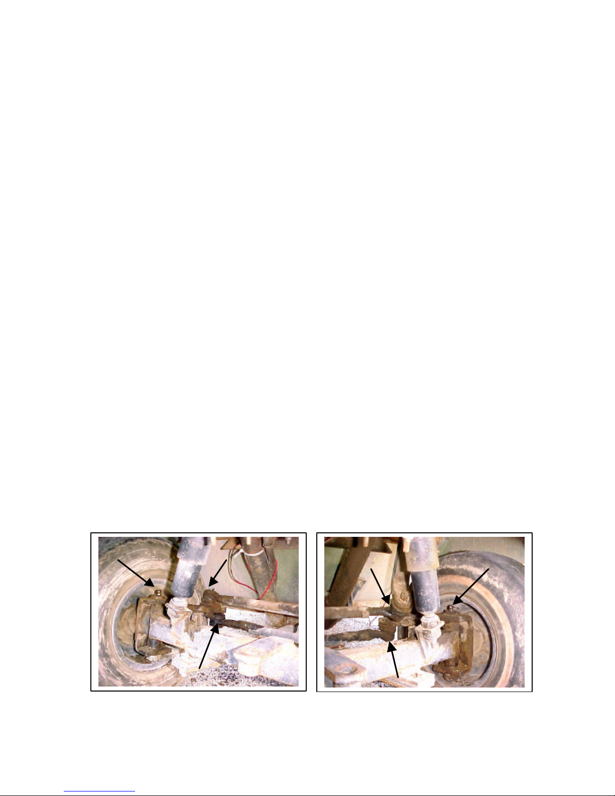
STEERING
Steering is a conventional automotive type. I strongly suspect the S-71 uses the same
components as were used for Otis gasoline-powered products of higher power and speed.
The steering assembly has a total of six grease fittings, three on each side as indicated by
the arrows on the photos below.
Page 15
15 Page
REAR AXLE AND DIFFERENTIAL
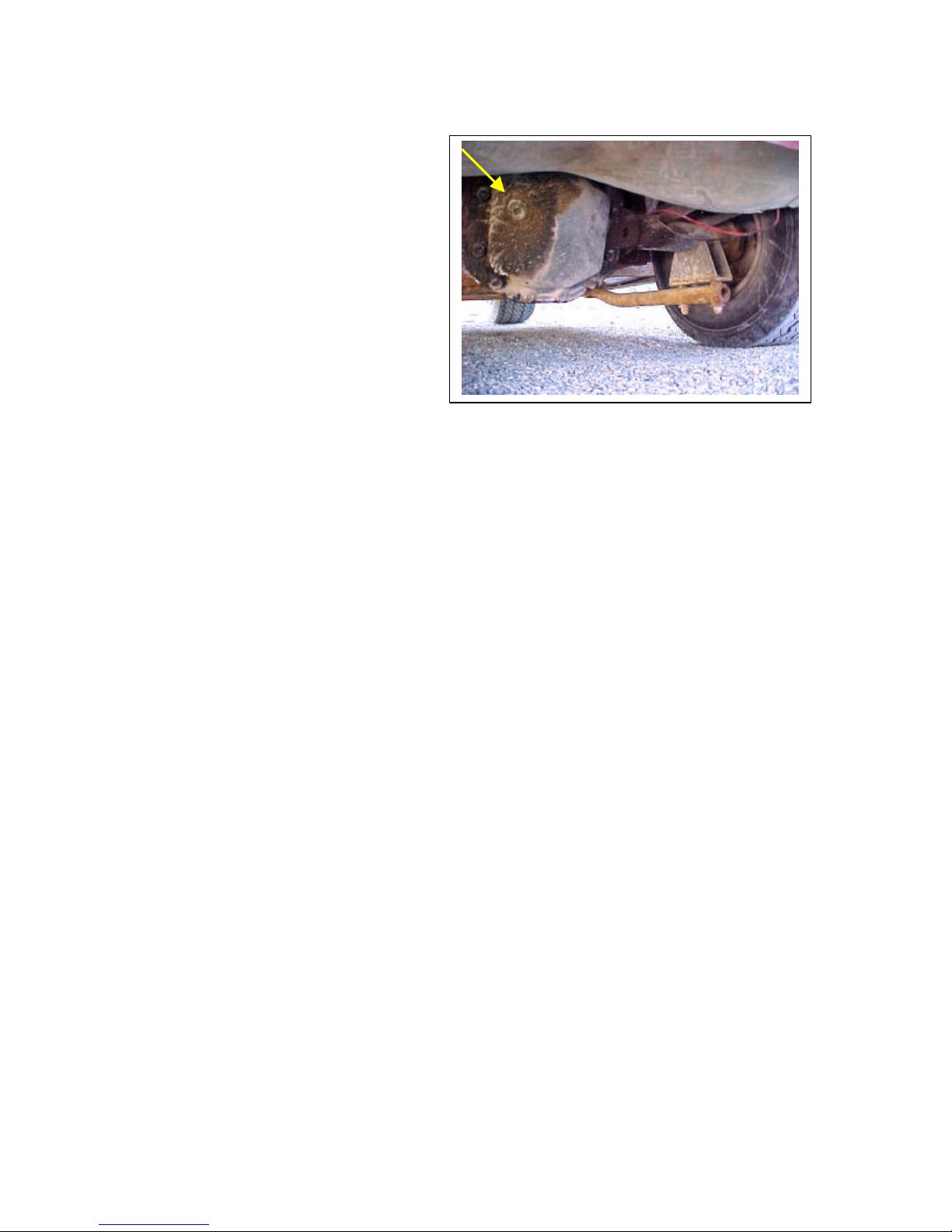
The rear axle and differential are of the
automotive type. The differential can
provide power to either rear wheel. I
strongly suspect the S-71 uses the
same components as were used for
Otis gasoline-powered products of
higher power and speed.
The differential cover (facing rear) has
an oil plug for inspecting and adding
gear oil (see photo). Standard 90weight gear oil is recommended.
Each rear wheel uses a ball-bearing wheel bearing located in the end of the axle. For
access, jack up the rear axle and remove the rear wheel. Remove the cotter pin and castle
nut holding the hub and pull the hub straight off- it is splined to the axle shaft. The
bearing will be visible at the end of the axle. This bearing should be flooded with clean
grease. I have not removed one of these so cannot say further the exact procedure for
bearing removal. The bearing appears to be retained by a plate that bolts to the end of the
axle housing (with a large opening for the axle and through which the bearing may be
viewed). To replace the hub align the splines of the hub and rear axle and push on.
Replace the castle nut and tighten until it is tight, then back off the nut until the cotter pin
can be inserted through the castle nut and axle and locked in place. Then replace the
wheel. The wheel lug nut torque is unknown to me but I use a 3/8 hand -ratchet and ¾inch deep well socket for this with good results.
SEATS AND BATTERY ACCESS
The two individual seats are bolted to a piece of ½-inch plywood (covered with indooroutdoor carpet) that is hinged at the front edge for access to the batteries. A rod and rodholder (for propping up this cover during battery maintenance) are located on the battery
side behind the driver’s seat. The passenger seat mounts with four bolts from the rear of
this cover into tapped nuts in the seat. The driver’s seat mounts to adjustable tracks so it
can be moved fore a nd aft to accommodate the driver. The tracks have threaded studs that
extend through the cover and are attached with washers and nuts. One of these nuts also
secures the rod and another one secures the rod holder.
Page 16
16 Page
OPERATOR CONTROL PANEL
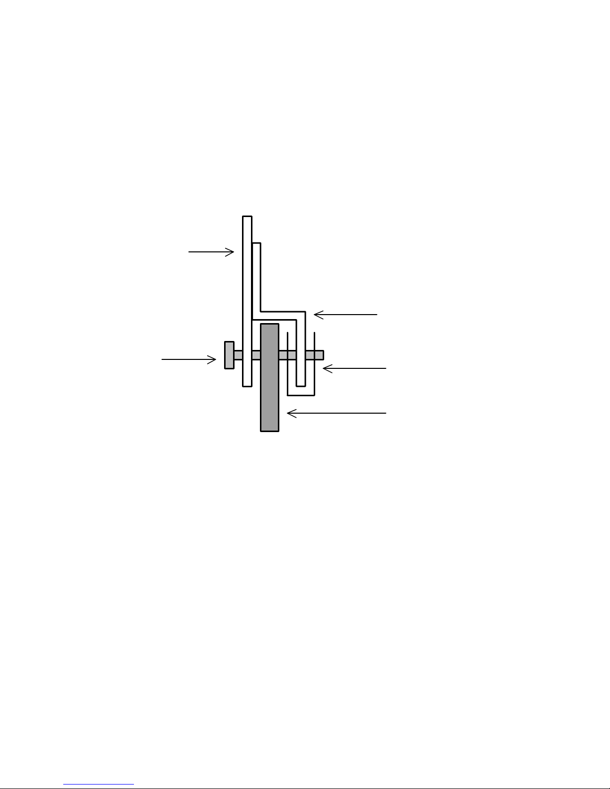
The operator cont rol panel mounts to the fiberglass body using a bolt, nut, and washer at
the top end (between the seats) and using either a bolt or sheet metal screw at the bottom
edge near the floor. Remove the upper bolt first. Then remove the bottom fastener- it
screws into a captive Tinnerman U-type self-retaining speed nut on the inside lip behind
the fiberglass. When the bolts are removed, lift up on the panel about ½-inch so the
bottom lip clears the fiberglass. The panel may then be pulled forward a few inches for
access to the components mounted on it. The heavy battery cables and studs on the
reversing switch may hang up on the fiberglass but a little patience and care will free the
panel for maintenance.
Bottom end of
control panel
Fastener
Lip part of control panel
Tinnerman speed nut
Fiberglass body (partial)
Page 17

17 Page
REFERENCES
[1] Otis / Westcoaster sales brochure entitled “full line”
Undated, circa early 1970’s. No Copyright in evidence.
[2] Circuits and Machines in Electrical Engineering, Volume II Machines
By John O. Kraehenbuehl and Max A. Fawcett
Second Edition, 1947, John Wiley & Sons, Inc., New York
Page 251.
[3] I.C.S. Reference Library (4 volumes)
Volume: Electric Railways, Interior Wiring
1904, International Textbook Company, Scranton
Section 24, Page 16.
INTERESTING WEBSITES
SUBJECT WEBSITE LINK
Electric Vehicle History www.econogics.com/ev/evhista.htm
EVA-Chloride See listing at www.econogics.com/ev/evhiste.htm
Otis Elevator Company www.otis.com
Otis Elevator Company See listing at www.econogics.com/ev/evhisto.htm
Trojan Batteries www.trojanbattery.com
Westcoaster No listing found
 Loading...