

OTIS OI-6900-X-X-T-2B Operation Manual


CAUTION
CAUTION: FOR SAFETY REASONS, THIS EQUIPMENT MUST BE OPERATED AND
SERVICED BY QUALIFIED PERSONNEL ONLY. READ AND UNDERSTAND THE
INSTRUCTION MANUAL COMPLETELY BEFORE OPERATING OR SERVICING.
DANGER
DANGER: OTIS INSTRUMENTS INC. OI-6900-X-X-T-2B IS AN AMBIENT AIR TOXIC GAS
SENSOR ASSEMBLY AND ONLY MONITORS IN THE IMMEDIATE VICINITY OF THE
SENSOR HOUSING. A SITE SURVEY IS REQUIRED IN ORDER TO DETERMINE THE BEST
PLACEMENT AND QUANTITY OF SENSOR ASSEMBLIES. IMPROPER INSTALLATION
CAN LEAD TO AN UNDETECTABLE GAS LEAK WHICH COULD RESULT IN PERSONAL
INJURY OR LOSS OF LIFE.


TABLE OF CONTENTS
TABLE OF CONTENTS
1 PRODUCT OVERVIEW .......................................................................................................................................... 1
1.1 INTRODUCTION .................................................................................................................................................... 1
1.2 PRODUCT SPECIFICATIONS ............................................................................................................................... 2
1.3 SYSTEM DIAGRAMS ............................................................................................................................................. 3
1.3.1 EXTERNAL SYSTEM DIAGRAM ........................................................................................................................... 3
1.3.2 INTERNAL SYSTEM DIAGRAM............................................................................................................................. 4
1.3.3 ASSEMBLY DIAGRAM ........................................................................................................................................... 5
2 INSTALLATION AND START-UP .......................................................................................................................... 6
2.1 PRODUCT PLACEMENT ....................................................................................................................................... 6
2.2 PRODUCT MOUNTING ......................................................................................................................................... 7
2.3 WIRING CONFIGURATIONS ................................................................................................................................. 7
2.3.1 OPENING THE ENCLOSURE ................................................................................................................................ 8
2.3.2 CONNECTING THE BATTERIES ........................................................................................................................... 8
2.3.3 CLOSING THE ENCLOSURE ................................................................................................................................ 9
2.4 SYSTEM START-UP .............................................................................................................................................. 9
2.5 NORMAL OPERATING MODE............................................................................................................................. 10
3 PRODUCT SETTINGS AND CONFIGURATION ................................................................................................. 11
3.1 RELAY TEST ........................................................................................................................................................ 11
3.1.1 PERFORMING THE RELAY TEST ...................................................................................................................... 12
3.2 NETWORK ID ....................................................................................................................................................... 12
3.3 SYSTEM INFORMATION ..................................................................................................................................... 13
3.4 NULL/CALIBRATION TIMER INFORMATION ..................................................................................................... 13
3.5 UNIT INFORMATION ........................................................................................................................................... 14
3.6 BACKGROUND SETTING.................................................................................................................................... 14
3.7 CALIBRATION METHOD ..................................................................................................................................... 15
3.8 DISPLAY SCREEN CONTRAST SETTING ......................................................................................................... 16
3.9 RETURN TO FACTORY DEFAULT SETTINGS .................................................................................................. 17
4 OPERATION SETTINGS ..................................................................................................................................... 19
4.1 POWERING THE DEVICE ................................................................................................................................... 19
4.1.1 POWERING ON ................................................................................................................................................... 19
4.1.2 POWERING OFF .................................................................................................................................................. 19
4.2 SENSOR CALIBRATION ...................................................................................................................................... 20
4.2.1 NULLING THE SENSOR (AUTO NULL) .............................................................................................................. 20
4.2.2 CALIBRATING THE SENSOR (MANUAL CAL) ................................................................................................... 22
4.2.3 CALIBRATING THE SENSOR (AUTO CAL) ........................................................................................................ 23
4.3 SENSOR RADIO ADDRESS ................................................................................................................................ 25
4.3.1 SENSOR RADIO ADDRESS SETTING ............................................................................................................... 25
5 PRODUCT MAINTENANCE................................................................................................................................. 26
5.1 SCHEDULED MAINTENANCE ............................................................................................................................. 26
5.2 SENSOR REPLACEMENT ................................................................................................................................... 27
5.3 BATTERY REPLACEMENT ................................................................................................................................. 28
5.4 PRODUCT TROUBLESHOOTING ....................................................................................................................... 30
5.5 PRODUCT REPLACEMENT PARTS AND ACCESSORIES ................................................................................ 31
OI-6900-X-X-T-2B OPS GUIDE_REV 1.1 i

TABLE OF CONTENTS
APPENDIX A: PRODUCT WARRANTY STATEMENT ............................................................................................................. 33
APPENDIX B: INFORMATION ABOUT RMA SERVICE REPAIRS ......................................................................................... 35
APPENDIX C: INFORMATION ABOUT RMA RETURNS FOR CREDIT .................................................................................. 37
ii OI-6900-X-X-T-2B OPS GUIDE_REV 1.1

PRODUCT OVERVIEW
NOTICE
This document should be read in its entirety before the initial operation of the product.
1 PRODUCT OVERVIEW
1.1 INTRODUCTION
The Otis Instruments, Inc. (Otis) GEN II Model OI-6900-X-X-T-2B (OI-6900) Non-Explosion-Proof Ambient Air Toxic
Gas Detector is designed to detect a wide range of toxic gases in many environments. The OI-6900 features nonintrusive magnetic switches that allow for complete system configuration, regular calibration, and product
maintenance to be performed in the field, without opening the enclosure and breaking the seal of the enclosure. Nonintrusive interface with the OI-6900 is made possible by use of the Otis Magnetic Tool included in the purchase of
the device.
The OI-6900 continuously monitors the gas level of the surrounding environment and reports once every minute, the
reporting rate will increase to once every five seconds when the detected gas is above the Background Gas setpoint. This set-point is adjustable to account for sites that may have a constant low level of gas always present
allowing the OI-6900 to maintain a long battery life. When the gas level drops below the set-point the reporting rate
will return to once every minute. The OI-6900 display screen will always show the present concentration of gas being
detected by the sensor assembly. More information about the Background Gas Set-point is found later in this manual.
This document is an operation manual containing diagrams and step-by-step instructions for the proper and safe
installation, start-up, configuration and settings, normal operation, and product maintenance of the OI-6900.
In this manual, the instructions reference the use of push-buttons, located on the front panel of the device. In certain
environments, the activation of the non-intrusive magnetic switches, through the use of the Otis Magnetic Tool, will
replace the directive of the button-press actions. To apply the Otis Magnetic Tool, hold the tool to the side of the
device enclosure adjacent to the push-button that you wish to activate. When the magnetic switch is toggled, an onscreen indicator will appear on the display screen, signifying that a connection was made.
Should a question arise during the use of the product, this document will serve as a first reference for the end-user.
For inquiries beyond the information and instructions provided within this manual, contact the sales representative
of this product for assistance.
OI-6900-X-X-T-2B OPS_GUIDE_REV 1.1 1

PRODUCT OVERVIEW
System Specifications
Operating Voltage
3.6 VDC 19Ah each, 38 Ah total Lithium-Thionyl (Li-SOCl2) Battery
Estimated Battery Life
Electrochemical Sensor - 2 Years Maximum
Photo Ionization Detector Sensor – 14 Days Maximum
Operating Temperature Range
-20⁰C to +54⁰C
Humidity Range
0% to 98% Relative Humidity, Noncondensing
Measurement Range
Varies based on gas type
Response Time
Varies based on gas type
WireFree Radio Option
GEN II 900 MHz – 52 Networks, 255 Sensors per Network
GEN II 2.4 GHz – 78 Networks, 255 Sensors per Network
RF Connection
N-Female Radio Frequency (RF) Connector
Display
Transflective (sunlight-readable)
102x64 LCD Screen
LED Back-Light
Interface
3 Push-Buttons (MENU, ADD, SUB)
3 Magnetic Switches for Non-Intrusive Calibration
Mechanical Specifications
Enclosure Materials
Aluminum Device Enclosure with Plastic Lid
Sensor Housing Material
Black Polypropylene Plastic with Stainless Steel Mesh Screen
Product Dimensions
5.37" L x 5.11" W x 15.76" H (Maximum w/ Attachments)
Product Weight
3.25 lbs
1.2 PRODUCT SPECIFICATIONS
2 OI-6900-X-X-T-2B OPS_GUIDE_REV 1.1
PRODUCT OVERVIEW
⑫
⑪
⑬
1.3 SYSTEM DIAGRAMS
Refer to the following diagrams for identification of the external and internal system components that may be referred
to in this manual.
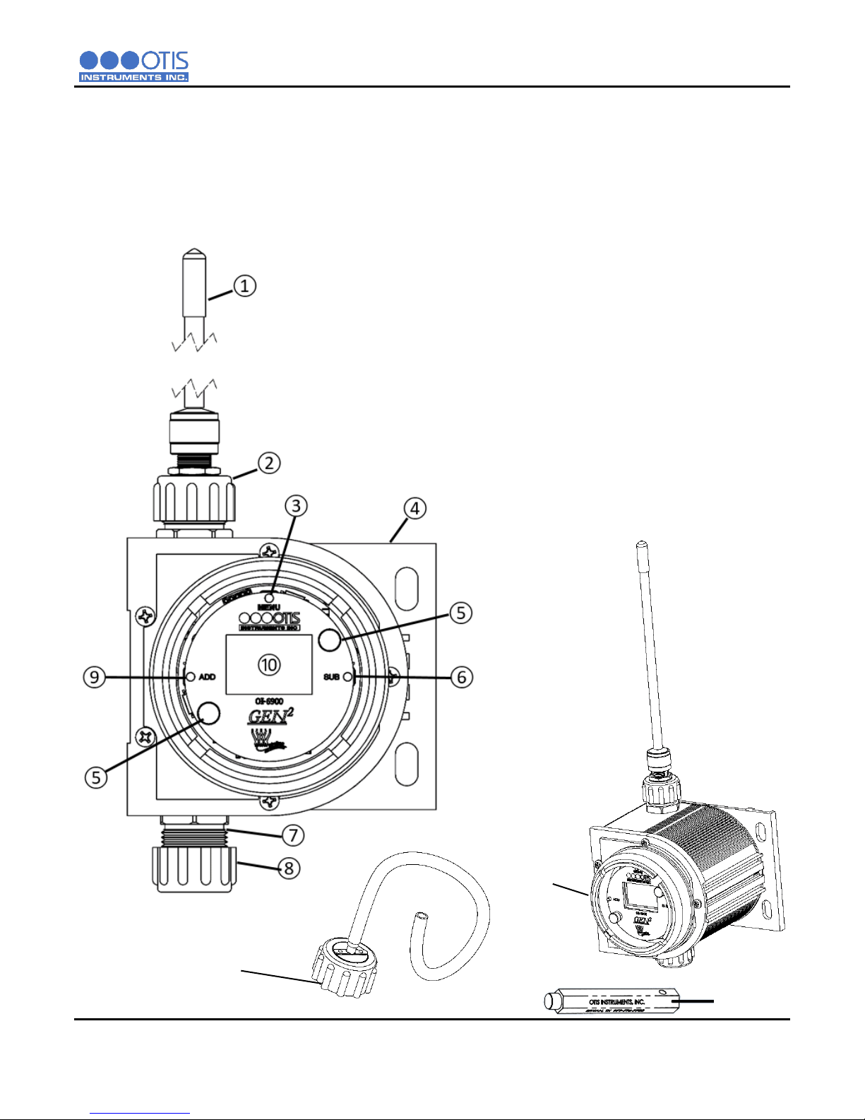
1.3.1 EXTERNAL SYSTEM DIAGRAM
1 Antenna
2 Antenna Fitting
3 MENU Button
4 Enclosure
5 Front Panel Thumbscrew
6 SUB Button
7 Sensor Housing Base
8 Sensor Housing Cap
9 ADD Button
10 LCD Display Screen
11 Enclosure Lid
12 Otis Magnetic Tool
13 Cal Adapter Kit
OI-6900-X-X-T-2B OPS_GUIDE_REV 1.1 3

PRODUCT OVERVIEW
1.3.2 INTERNAL SYSTEM DIAGRAM
1 Sensor Housing Connector
2 Sensor Housing Plug
3 Batteries
4 Radio Module
5 Battery Connectors
6 Antenna Fitting Connector
7 Battery Spring Clips
4 OI-6900-X-X-T-2B OPS_GUIDE_REV 1.1
PRODUCT OVERVIEW
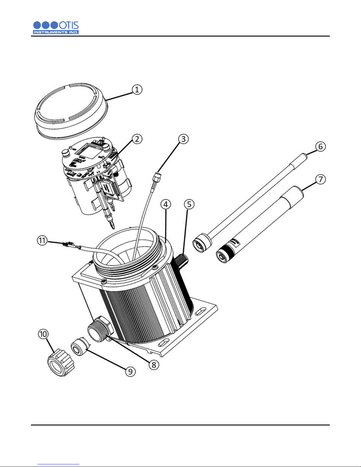
1.3.3 ASSEMBLY DIAGRAM
1 Enclosure Lid
2 Internal System
3 Antenna Fitting Connector
4 Enclosure
5 Antenna Fitting
6 900 MHz Antenna
OR
7 2.4 GHz Antenna
8 Sensor Housing Base
9 Sensor Element
10 Sensor Housing Cap
11 Sensor Housing Plug
OI-6900-X-X-T-2B OPS_GUIDE_REV 1.1 5

INSTALLATION AND STARTUP
NOTICE
These guidelines are ONLY intended as a general directive for the placement of the OI-6900. This information
should NOT serve as a complete list when considering all potential parameters for the proper location of the unit.
It is STRONGLY advised that a third party Certified Industrial Hygienist, or other Certified Safety Professional,
conduct a site survey and annotate the location and quantity of detection devices that should be installed for
EVERY installation of EVERY site.
2 INSTALLATION AND START-UP
2.1 PRODUCT PLACEMENT
The installation instructions, and any other information supplied by Otis, provide only basic guidelines relating to the
properties of toxic gas and the effects of environmental conditions on the OI-6900 device. Sensor placement should
be determined in consultation with the site safety personnel, as well as those knowledgeable of: (1) the site/facility
where the equipment is being installed and (2) the potentially present gas types and their dispersion. Otis strongly
recommends that the end-user consults with the appropriate third party Health, Safety and Environmental (HSE) and
Industrial Hygiene (IH) professionals to determine the final quantity and placement of your gas detection devices.
The primary purpose of the OI-6900 is to provide an early warning of the accumulation of toxic gas, in order to
minimize hazards to people and property. Proper placement of the device is paramount to achieving this goal.
The following general guidelines should be considered when determining the placement of the OI-6900:
The unit should be placed greater than 6.5 Feet/2 Meters away from a monitor in order to ensure reliable
communications
The unit shall be placed such that the position of the sensor housing is pointing downward to the ground.
Avoid installing the unit in a location where airborne particles could cover or coat the sensor head.
The unit should be placed in an area that will produce the highest gas concentration. Enclosed corners and
stopping points of moving devices are two areas susceptible to a buildup of toxic gas.
In order to provide an accurate representative sample of a room, care should be taken to avoid locating the
unit near a room entrance, fresh air intake vent, or vehicle/generator exhaust point.
The unit should be placed as close as physically possible to the source of the potential toxic gas leak.
Consider placing the unit in a seldom used area, such as a warehouse, storage area, or other unfrequented
location.
Consider accessibility for regular calibration and other required maintenance.
When monitoring a ventilated gas cylinder storage area, the unit should be placed near the air return vent.
When monitoring an outdoor or open-air area, the unit should be placed near the air intake of the HVAC
system of the building.
When monitoring for the potential presence of multiple toxic gas types, the unit should be calibrated for the
least cross-sensitive toxic gas.
6 OI-6900-X-X-T-2B OPS_GUIDE_REV 1.1

INSTALLATION AND STARTUP
CAUTION
The internal components can be static sensitive. Use caution when opening the enclosure and handling
internal components.
DO NOT use any metal objects or tools to remove the terminal board from the internal system.
DO NOT mix old and new batteries.
WARNING
When securing the lid onto the device, tighten the enclosure lid by hand ONLY. Overtightening of the lid by
use of hand-tools could result in damage to the O-ring, potentially compromising the moisture seal, resulting
in an unsafe environment.
Use ONLY Otis supplied batteries in this device.
2.2 PRODUCT MOUNTING
It is recommended to mount the unit to a solid structure (such as a concrete wall, steel column, or angle iron) where
a minimum of vibration will be transmitted to the unit. Alternately, a pole may be used along with a strap or a U-bolt,
as long as it is rigid and of sufficient strength. Wooden structures are not recommended for mounting, as they trap
moisture (which could affect sensor performance) and their mounting rigidity degrades over time (screws/bolts
weaken and fall out or corrode).
Any style of bolt or screw may be used as long as it is steel and meets or exceeds the following:
Maximum ¼"-20 bolt or ؼ" screw (length varies with user need)
Flat washers for bolts/nuts/screws
Minimum Grade 5 (or better)
Corrosion protection for all hardware (paint, galvanize, zinc plating, etc.)
2.3 WIRING CONFIGURATIONS
The OI-6900 is powered by dual 3.6V/19AH Lithium-Thionyl batteries. The batteries should be replaced in pairs and
you should not mix old and new batteries.
OI-6900-X-X-T-2B OPS_GUIDE_REV 1.1 7
INSTALLATION AND STARTUP
NOTICE
Disconnecting the sensor connector plug from the sensor housing connector and the antenna fitting
cable will allow for the complete removal of the internal system from the device enclosure.
Disconnecting the internal system may provide ease in accessing the control board terminals for
connecting the battery plug into the battery connectors. If this step is performed, it is essential that all
connections are rejoined before returning the internal system back into the enclosure.
2.3.1 OPENING THE ENCLOSURE
To prepare the OI-6900 for installation, you must first open the device, exposing the control board and its
components to connect the batteries.
1. Remove the enclosure lid, unscrewing it from the device enclosure. Set aside.
2. Gripping the front panel thumbscrews, lift the internal system out of the enclosure and rest it against
the rim of the enclosure opening.
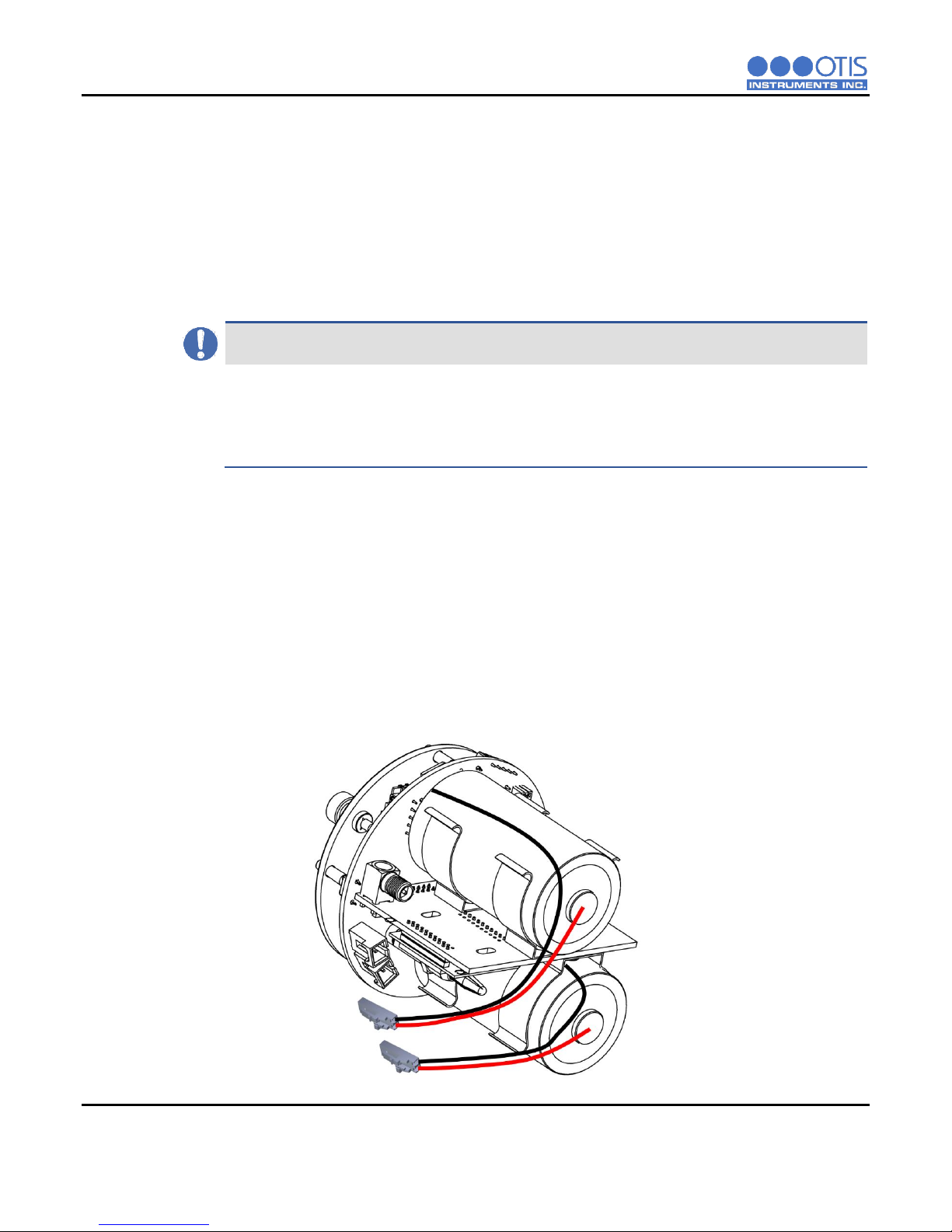
2.3.2 CONNECTING THE BATTERIES
To provide power to the OI-6900 you will need to connect the battery connectors to the OI-6900 battery
terminals located on the control board. Refer to the following instructions for how to connect the batteries
to your device:
On the GEN II Model OI-6900 Detector:
1. Plug the battery on the bottom of the radio board into the closer 2-pin battery terminal.
2. Plug the battery on the top of the radio board into the other available 2-pin battery terminal.
8 OI-6900-X-X-T-2B OPS_GUIDE_REV 1.1
 Loading...