

OTIS GEN2 OI-7032 Operation Manual

Model OI-7032
32-Channel
_____________________________________
Operation Manual
Revision 2.5w
_______________________________________________________________________________________
___________________________________________________________
Product Overview
The Otis Instruments, Inc. GenII OI-7032 (32-Channel) is a Hybrid Monitor that supports up to 32
WireFree sensor units, and up to four 4-20mA input sensors (when only 28 channels are setup as
WireFree).
The OI-7032 is backward compatible with GenI WireFree sensor units, and also supports GenII Wirefree
sensor units (configurable).
For additional information regarding the OI-7032, see the Appendices at the end of this operation
manual.
2

Table of Contents
Product Overview.......................................................................................................................................2
Introduction................................................................................................................................................ 5
Warnings..................................................................................................................................................... 6
Complete System Diagrams...................................................................................................................... 7
Front Panel.........................................................................................................................................................................7
Internal Diagram................................................................................................................................................................8
Terminal Board...................................................................................................................................................................9
Touchscreen (Front).........................................................................................................................................................10
Touchscreen (Back)..........................................................................................................................................................10
AC (Delta) Power Supply................................................................................................................................................. 11
Internal Diagram – As Wired from the Factory..............................................................................................................12
Internal Diagram – Completely Wired............................................................................................................................ 13
Wiring Configurations.............................................................................................................................14
DC Power-in (24 Volts DC (nominal; 22-26 Volts DC))................................................................................................. 14
AC Power Supply Connection..........................................................................................................................................17
Touchscreen Power Connection...................................................................................................................................... 19
Touchscreen Connection..................................................................................................................................................22
Memory Installation.........................................................................................................................................................25
Connecting Sensors..........................................................................................................................................................27
Connecting Sensor 1................................................................................................................................................... 27
Connecting Sensor 2................................................................................................................................................... 29
Connecting Sensor 3................................................................................................................................................... 31
Connecting Sensor 4................................................................................................................................................... 33
Relay Configurations....................................................................................................................................................... 35
Connecting Relay 1..................................................................................................................................................... 35
Connecting Relay 2..................................................................................................................................................... 37
Connecting Relay 3..................................................................................................................................................... 39
Connecting Relay 4..................................................................................................................................................... 41
Power On/Off............................................................................................................................................43
Basic Operation - Home Screen Navigation.......................................................................................... 44
Trend Chart...................................................................................................................................................................... 45
Real-Time Values..............................................................................................................................................................48
Time Since Last Calibration and Null.............................................................................................................................51
Autoscroll On/Off.............................................................................................................................................................53
Channel Configuration.................................................................................................................................................... 54
Set as Wired or WireFree (Channels 29-32 ONLY).................................................................................................57
Processing................................................................................................................................................................ 57
Relay Configuration.................................................................................................................................................58
Setting Radio Address (WireFree)........................................................................................................................... 59
Setting Scale (Wired)............................................................................................................................................... 60
Setting Sensor Location........................................................................................................................................... 61
Duplicate Settings ................................................................................................................................................... 62
Channel Off .............................................................................................................................................................64
Configuration Menu Navigation.............................................................................................................65
Entering Configuration Menu.........................................................................................................................................66
View Monitor Serial #...................................................................................................................................................... 67
View Date Manufactured................................................................................................................................................. 67
Calibration Mode..............................................................................................................................................................68
Relay Tests........................................................................................................................................................................ 69
OI-7032 Restart................................................................................................................................................................ 70
VIEW Modbus Output Settings: Address........................................................................................................................ 71
3

VIEW Modbus Output Settings: Baud Rate....................................................................................................................71
VIEW Radio Settings: Radio Timeout............................................................................................................................. 72
VIEW Gen II Radio Settings: Network ID......................................................................................................................72
VIEW Gen II Radio Settings: Primary or Secondary Monitor...................................................................................... 73
VIEW OI-7032 Reset to Factory Default........................................................................................................................ 73
VIEW Relay Settings: Relays 1-4 (Failsafe)................................................................................................................... 74
VIEW Relay Settings: Fault Terminal.............................................................................................................................74
VIEW Relay Settings: Fault Relay Assign...................................................................................................................... 75
Configuration Menu Modifications (Second-Level Configuration Menu).........................................76
MODIFY Modbus Output Settings: Address...................................................................................................................77
MODIFY Modbus Output Settings: Baud Rate.............................................................................................................. 78
MODIFY Radio Settings: Radio Timeout....................................................................................................................... 78
MODIFY Gen II Radio Settings: Network ID................................................................................................................ 79
MODIFY Gen II Radio Settings: Primary or Secondary Monitor.................................................................................79
MODIFY OI-7032 Reset to Factory Default...................................................................................................................80
MODIFY Relay Settings: Relays 1-4 (Failsafe)..............................................................................................................80
MODIFY Relay Settings: Fault Terminal....................................................................................................................... 81
MODIFY Relay Settings: Fault Relay Assign.................................................................................................................81
Relay Indicator......................................................................................................................................... 82
Fault Indicator..........................................................................................................................................83
Fault Status...................................................................................................................................................................... 83
Channel On Without Wired Sensor Connected (Fault).......................................................................................... 84
F1: Check Sensor Cable............................................................................................................................................. 84
F4: Check Sensor Board.............................................................................................................................................85
Error Messages.........................................................................................................................................86
Double-Primary Error......................................................................................................................................................86
Autoscroll Error............................................................................................................................................................... 87
APPENDIX A: Software Installation..................................................................................................... 88
Installation................................................................................................................................................ 89
HMI Software...................................................................................................................................................................89
APPENDIX B: Reading USB Drive........................................................................................................93
USB Drive................................................................................................................................................. 94
Removing the USB Drive................................................................................................................................................. 94
Reading the USB Drive.................................................................................................................................................... 94
Opening the Datalog Files.......................................................................................................................................... 94
Opening the Easy Converter Software..................................................................................................................... 94
Converting the Datalog File to an .xls (spreadsheet) File....................................................................................... 97
Viewing the Datalog File............................................................................................................................................ 97
When Finished Reading the USB Drive....................................................................................................................97
APPENDIX C: 4-20mA Loop Current Introduction............................................................................ 98
4-20mA Current Loop Introduction................................................................................................................................ 99
Overview........................................................................................................................................................................... 99
Calculations......................................................................................................................................................................99
Measuring Current.........................................................................................................................................................100
Specifications.......................................................................................................................................... 101
4

Introduction
This document is an Operation Manual containing diagrams and step-by-step instruction for proper
operation of the Otis Instruments, Inc. GenII OI-7032. This document should be read before initial
operation of the product.
Should a question arise during the use of the product, this document will serve as a first reference for
consultation. If further questions arise, or if the device is not working properly, please contact the sales
representative of this product.
5

Warnings
• The OI-7032 should only be used in an environment that constantly remains between the range of
-20 to 122 degrees Fahrenheit. If the OI-7032 is at risk of being exposed to temperatures that are
outside the previously stated range, DO NOT install the device in that location. For applications
in areas with the potential of reaching extreme temperatures, Otis Instruments recommends using
the OI-7032 indoors only (in a temperature-controlled environment).
• Even when the Power switch is in the off position, the AC and DC terminals are still hot—
regardless of if the device is wired as DC.
• Wiring Configuration Warnings:
● Provide a clean and stable 24 Volts DC (nominal; 22-26 Volts DC) voltage. Failure to to do
so may cause the unit (and any wired sensors that are connected to the unit) to not operate
properly.
● Voltage spikes higher than 26 Volts may damage the unit.
● Solar Panel power (with battery backup): This options may be used to power the unit,
however, care must be taken to ensure the proper voltage and wattage is used.
NOTE: The size that the solar panel should be (10, 30, 50, or 100 watts, for example) depends
on several factors, including: geographical area, line-of-sight access to the sun, number of
wired sensors connected, and weather conditions.
Please consult a solar panel manufacturer for specific details. Otis Instruments, Inc. may
also be contacted to provide guidance and recommendations.
6

Complete System Diagrams
The following diagrams should be consulted for identification of Panels, Boards, and any other system
component that may be referred to in this Operation Manual.
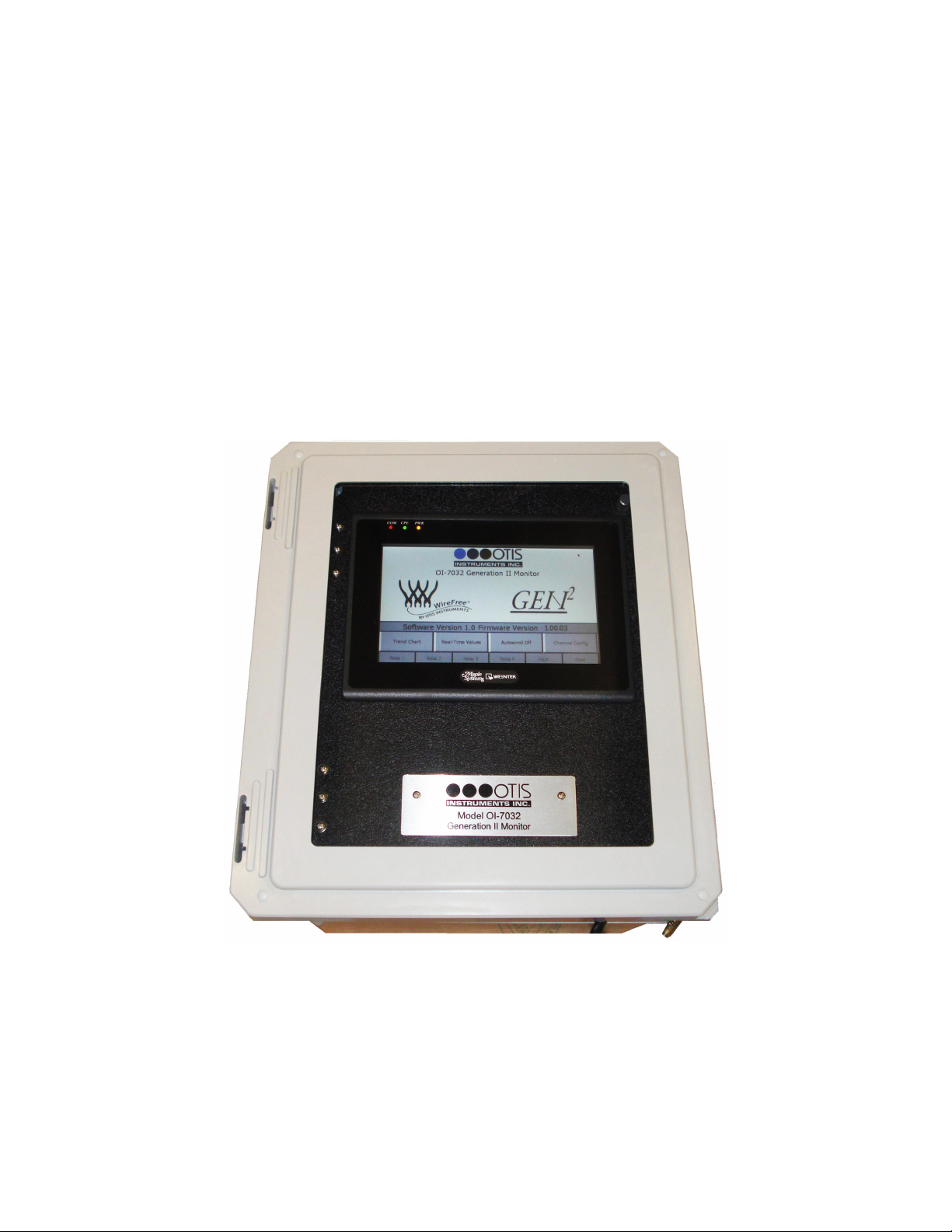
Front Panel
7
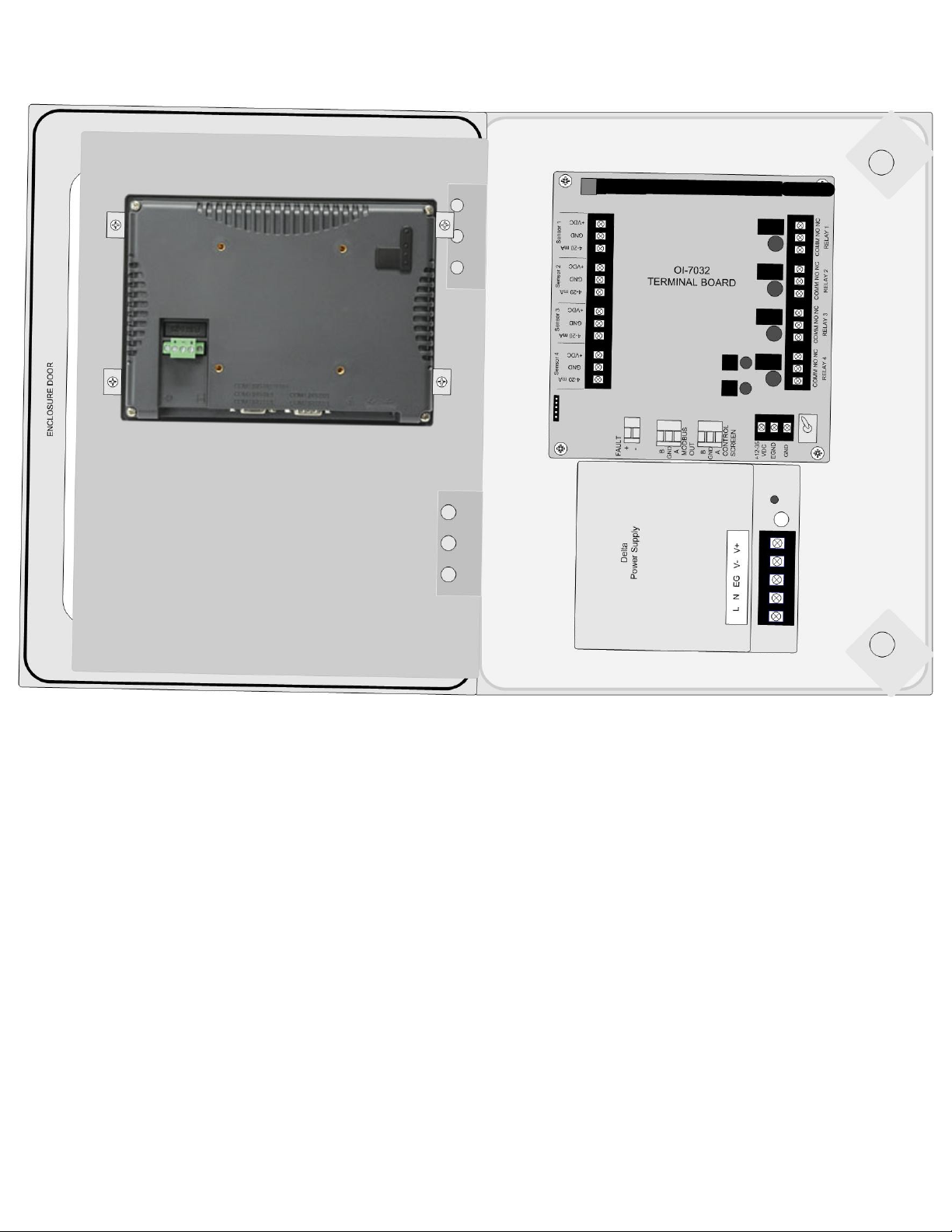
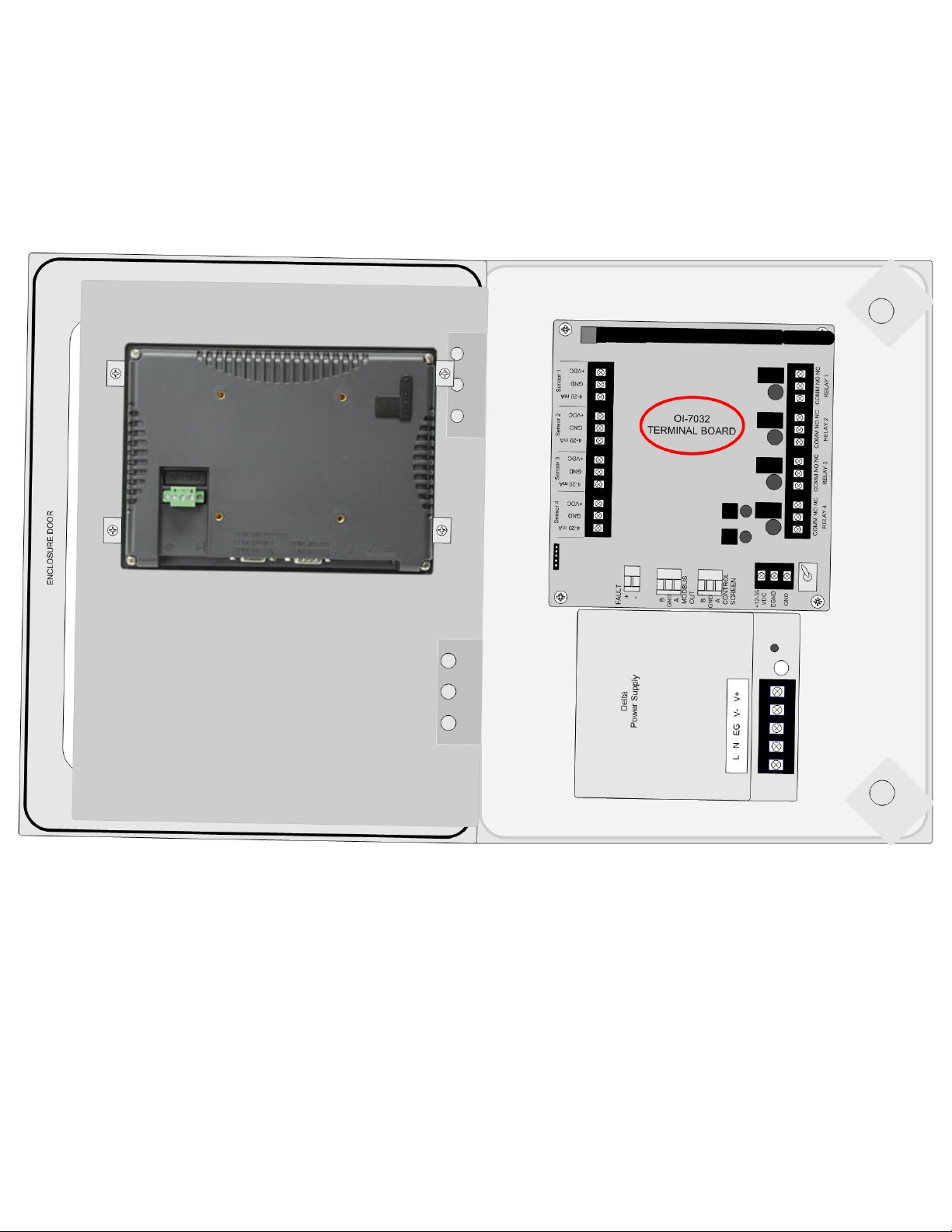
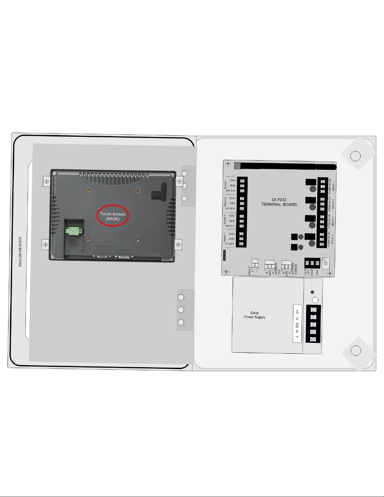
Internal Diagram
8
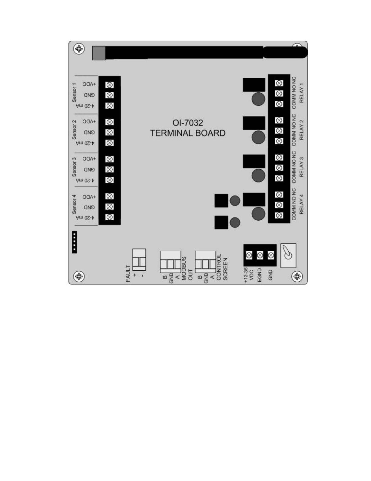
Terminal Board
9
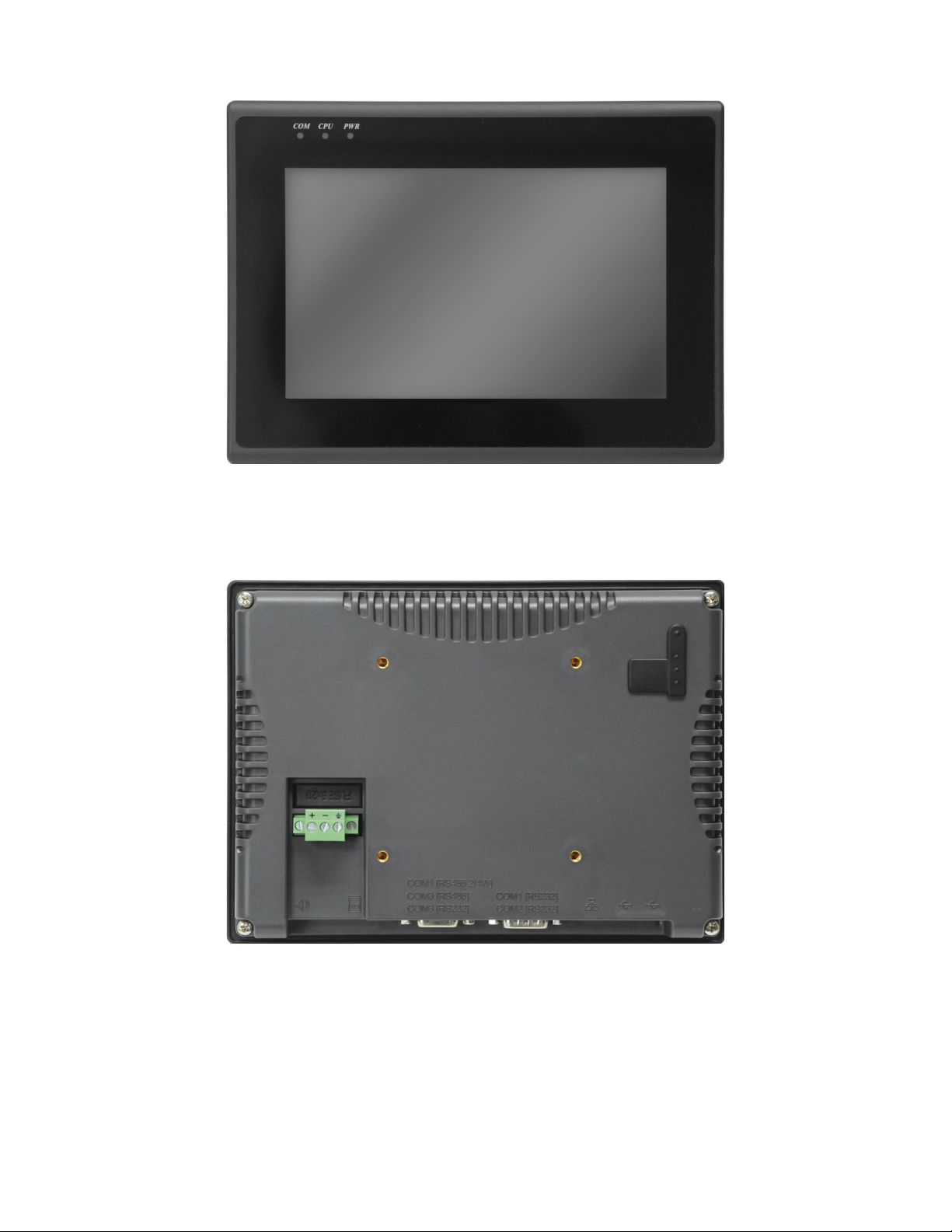
Touchscreen (Front)
Touchscreen (Back)
10
AC (Delta) Power Supply
11

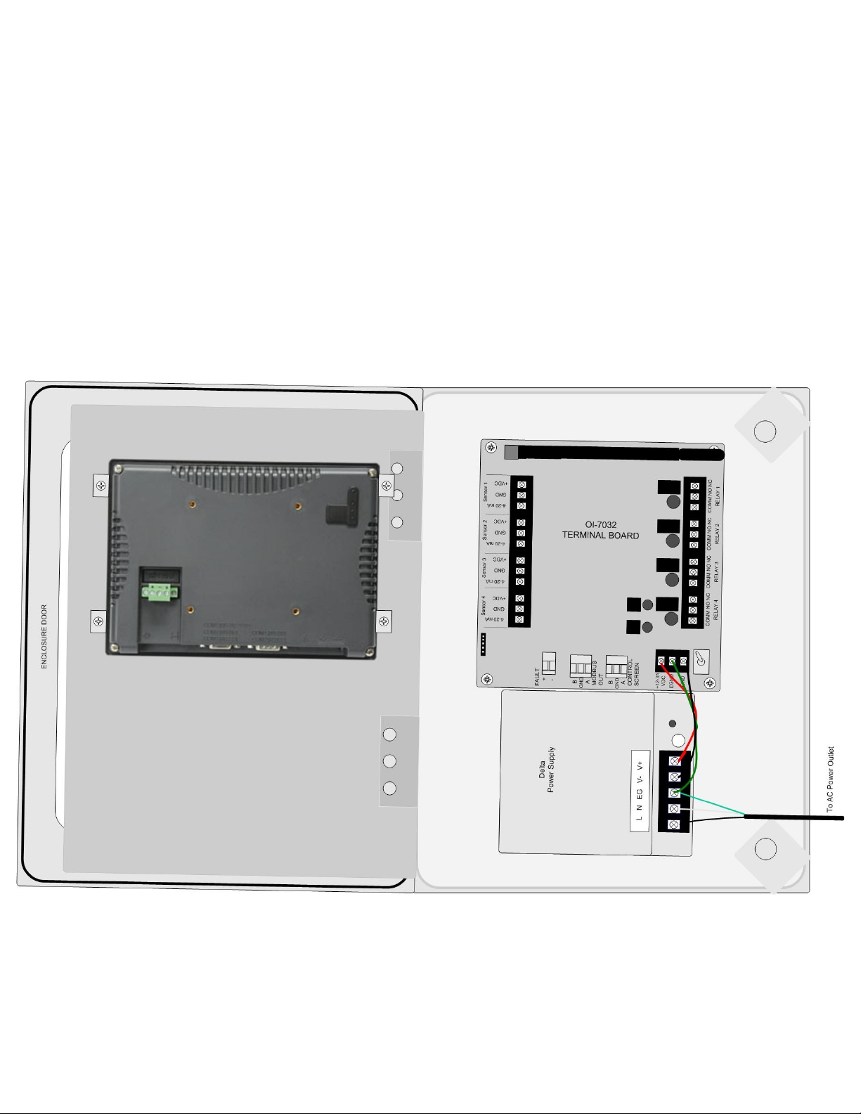
Internal Diagram – As Wired from the Factory
12

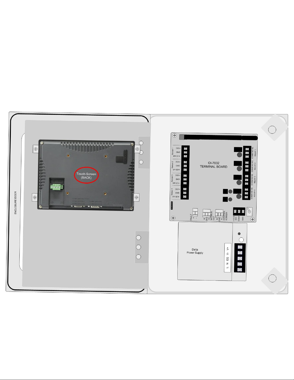
Internal Diagram – Completely Wired
13

Wiring Configurations
The following Wiring Configurations must be completed before initial operation of the product.
DC Power-in (24 Volts DC (nominal; 22-26 Volts DC))
NOTE: The unit will be wired for the power-type that is requested by the purchaser when
shipped from Otis Instruments, Inc.
When wiring the device, the following should be considered:
● Provide a clean and stable 24 Volts DC (nominal; 22-26 Volts DC) voltage. Failure to to do
so may cause the unit (and any wired sensors that are connected to the unit) to not operate
properly.
● Voltage spikes higher than 26 Volts may damage the unit.
● Solar Panel power (with battery backup): This options may be used to power the unit,
however, care must be taken to ensure the proper voltage and wattage is used.
NOTE: The size that the solar panel should be (10, 30, 50, or 100 watts, for example) depends
on several factors, including: geographical area, line-of-sight access to the sun, number of
wired sensors connected, and weather conditions.
Please consult a solar panel manufacture for specific details. Otis Instruments, Inc. may
also be contacted to provide guidance and recommendations.
14
DC Power-in (24 Volts DC (nominal; 22-26 Volts DC)) cont...
1. Open the enclosure box to expose the Front Panel.
2. Unscrew the two thumb-screws on the Front Panel.
3. Open the Front Panel so that the Terminal Board is exposed.
15
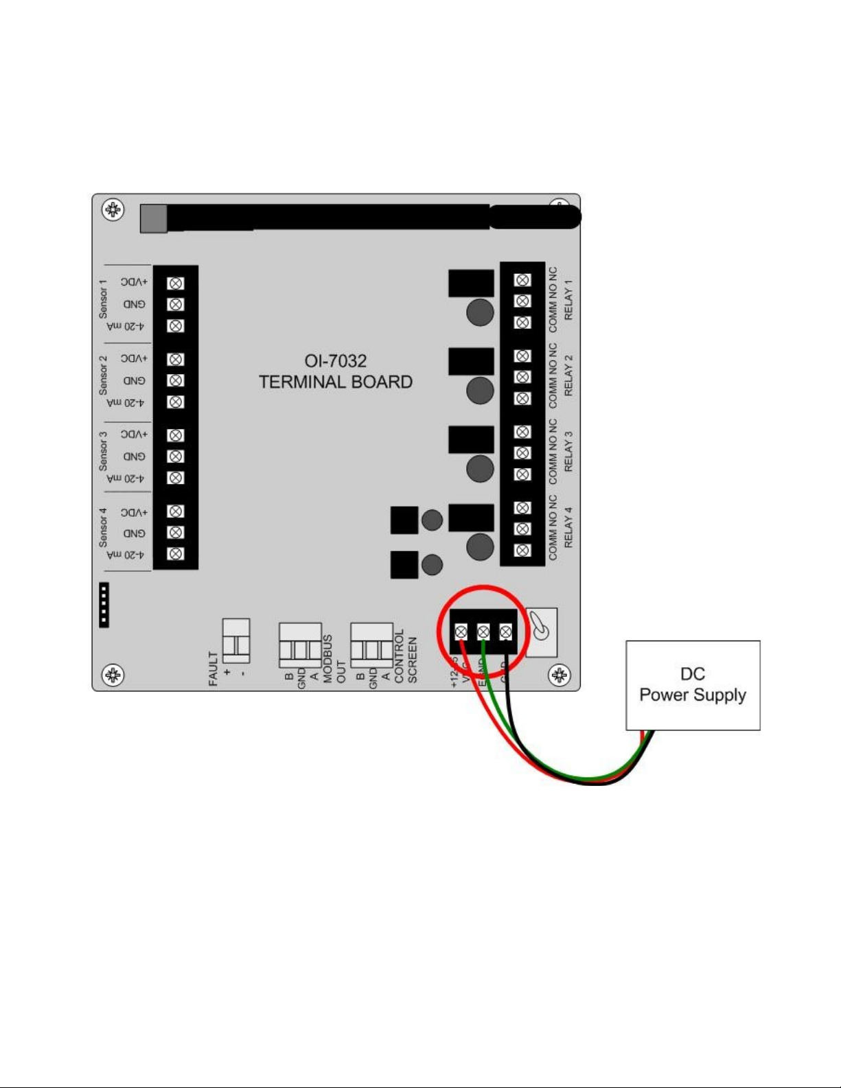
DC Power-in (24 Volts DC (nominal; 22-26 Volts DC)) cont...
4. Locate the Power Terminal (on the lower right side of the Terminal Board).
5. Connect the DC Power Supply live wire (red) to the terminal marked “+12-35 VDC”.
6. Connect the DC Power Supply Ground wire (black) to the terminal marked “GND”.
7. If desired, connect an Earth Ground wire (green) to the terminal marked “EGND” (required for
surge suppression).
8. Close the Front Panel.
9. Screw in the thumb-screws.
10.Close the enclosure box.
16
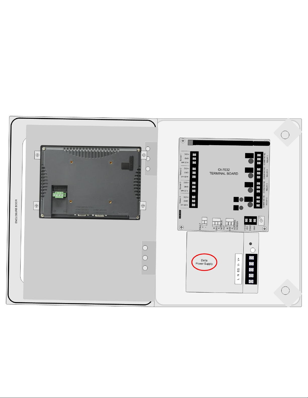
AC Power Supply Connection
For AC Power applications, the Delta Power Supply located below the Terminal Board should be used.
NOTE: The unit will be wired for the power-type that is requested by the purchaser when
shipped from Otis Instruments, Inc.
1. Open the enclosure box to expose the Front Panel.
2. Unscrew the two thumb-screws on the Front Panel.
3. Open the Front Panel so that the AC (Delta) Power Supply is exposed.
17
AC Power Supply Connection cont...
4. Connect a positive (red) wire to the Power Terminal terminal labeled “+12-35 VDC” on the
Terminal Board.
5. Connect the other end of that same positive (red) wire from the Terminal Board to the terminal
labeled “+V” on the Delta power supply.
6. Connect a negative (black) wire from the Power Terminal terminal labeled “GND” on the
Terminal Board.
7. Connect the other end of that same negative (black) wire from the Terminal Board to the terminal
labeled “-V” on the Delta power supply.
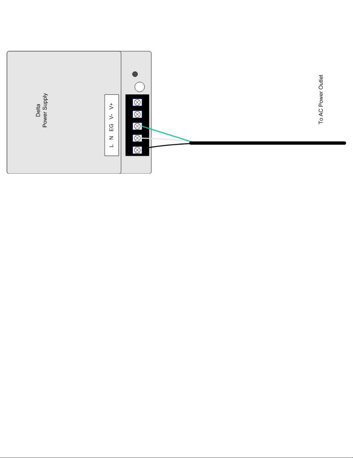
8. There will be three wires (black, white and green) pre-wired from the Delta power supply
terminals “L” (AC Load IN), “N” (AC Neutral IN), and “EG” (Chassis GND or Earth GND). This
set of wires will be used to plug into an AC power outlet ONCE ALL WIRING
CONFIGURATIONS ARE COMPLETE.
9. Close the Front Panel.
10.Screw in the thumb-screws.
11.Close the enclosure box.
18
Touchscreen Power Connection
NOTE: The Touchscreen power connection will be pre-wired for use when the unit is
shipped from Otis Instruments, Inc.
1. Open the enclosure box to expose the Front Panel.
2. Unscrew the two thumb-screws on the Front Panel.
3. Open the Front Panel so that the back of the Touchscreen is exposed.
19
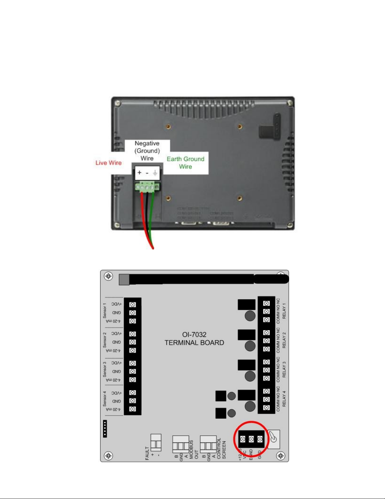
Touchscreen Power Connection cont...
4. Locate the Touchscreen's Power Terminal.
5. Connect the positive DC Supply wire (red) to the terminal labeled “+”.
6. Connect the negative DC Supply wire (black) to the terminal labeled “-”
7. Connect an earth ground wire (green) to the ground terminal.
8. Locate the Power Supply Terminal Block on the Terminal Board.
20

Touchscreen Power Connection cont...
9. Connect the positive DC Supply wire (red) to the terminal labeled “12-32 VDC” on the Power
Supply Terminal Block.
10.Connect the negative DC Supply wire (black) to the terminal labeled “GND” on the Power Supply
Terminal Block.
11.Connect the earth ground wire (green) to the terminal labeled “EGND” on the Power Supply
Terminal Block.
12.Close the Front Panel.
13.Screw in the thumb-screws.
14.Close the enclosure box.
21
Touchscreen Connection
NOTE: The OI-7032 Touchscreen will be pre-wired when the unit is shipped from Otis
Instruments, Inc.
1. Open the enclosure box to expose the Front Panel.
2. Unscrew the two thumb-screws on the Front Panel.
3. Open the Front Panel so that the back of the Touchscreen is exposed.
22
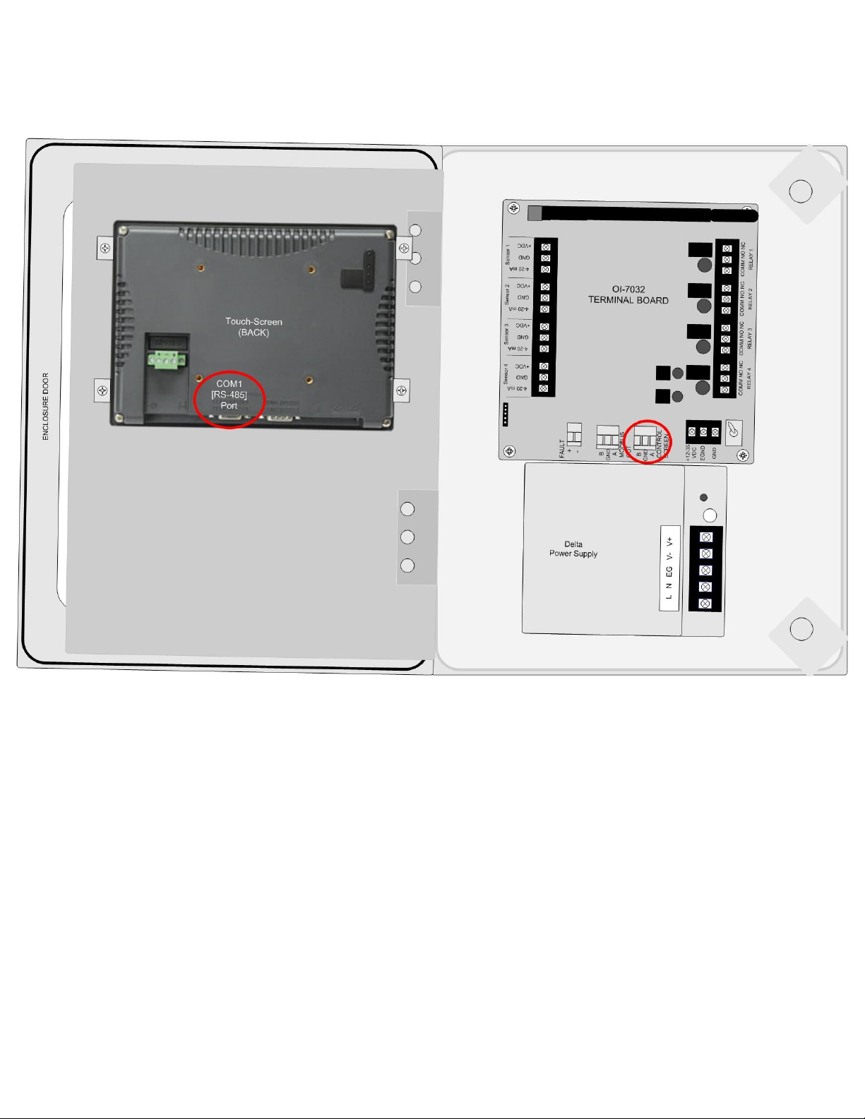
Touchscreen Connection cont...
4. Locate the COM Port and the Control Screen Terminal Block.
5. Plug the DB-9 connector into the COM1 Port.
23
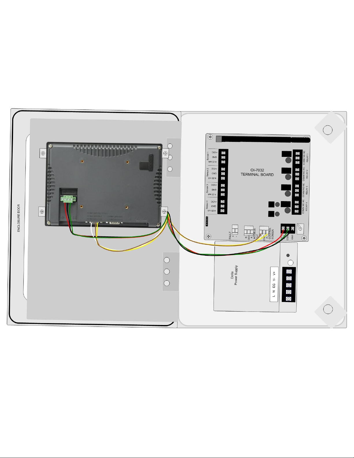
Touchscreen Connection cont...
6. Connect the yellow wire from the DB-9 connector to the terminal labeled “A” on the Control
Screen Terminal Block.
7. Connect the white wire from the DB-9 connector to the terminal labeled “GND” on the Control
Screen Terminal Block.
8. Connect the brown wire from the DB-9 connector to the terminal labeled “B” on the Control
Screen Terminal Block.
9. Close the Front Panel.
10.Screw in the thumb-screws.
11.Close the enclosure box.
24

Memory Installation
NOTE: The maximum memory card capacity is 2GB.
NOTE: The OI-7032 memory card will be pre-installed in the touch- screen when the unit is
shipped from Otis Instruments, Inc.
1. Open the enclosure box to expose the Front Panel.
2. Unscrew the two thumb-screws on the Front Panel.
3. Open the Front Panel so that the back of the Touchscreen is exposed.
25
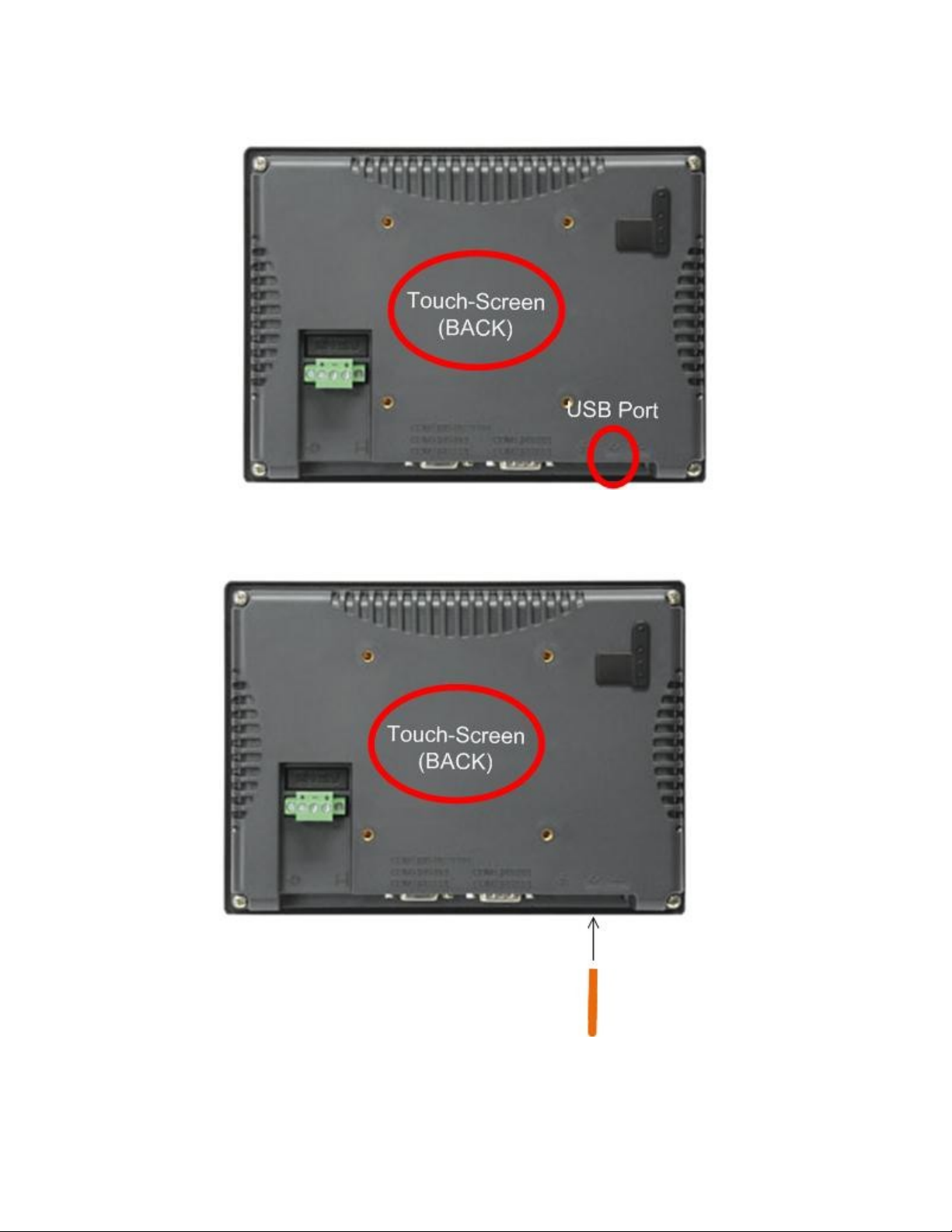
Memory Installation cont...
4. Locate the USB Port on the back of the Touchscreen.
5. Insert a USB-compatible memory card into the USB Port.
6. Close the Front Panel.
7. Screw in the thumb-screws.
8. Close the enclosure box.
26
Connecting Sensors
The OI-7032 is capable of monitoring up to four wired (4-20mA) sensors. Sensor connection should be
completed according to the following instructions.
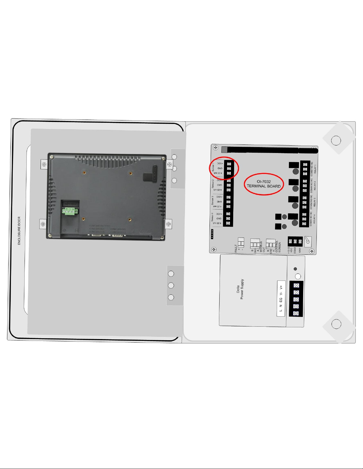
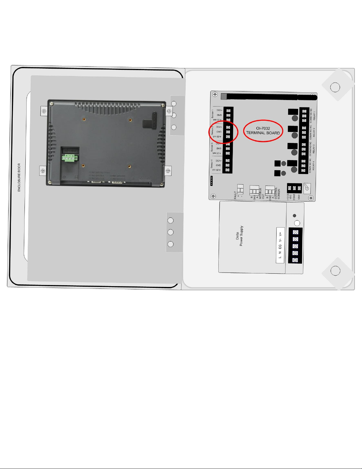
Connecting Sensor 1
1. Locate the Sensor 1 Terminal Block on the Terminal Board.
27
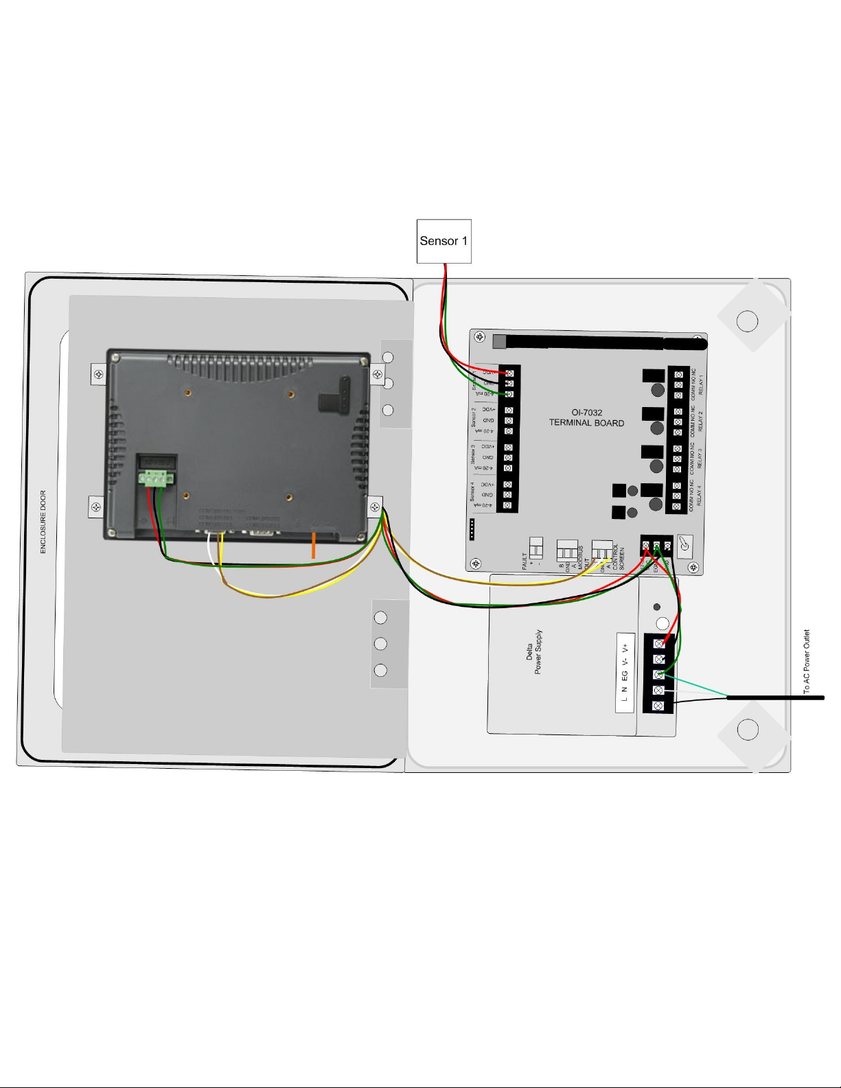
Connecting Sensor 1 cont...
2. Connect the positive (red) wire to the terminal labeled “+VDC”.
3. Connect the signal (green) wire to the terminal labeled “4-20mA”.
4. Connect the neutral (black) wire to the terminal labeled “GND”.
28
Connecting Sensor 2
1. Locate the Sensor 2 Terminal Block on the Terminal Board.
29
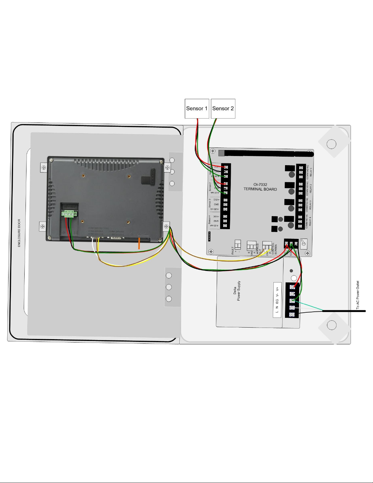
Connecting Sensor 2 cont...
2. Connect the positive (red) wire to the terminal labeled “+VDC”.
3. Connect the signal (green) wire to the terminal labeled “4-20mA”.
4. Connect the neutral (black) wire to the terminal labeled “GND”.
30
 Loading...