

Otima DVR1601X User Manual
1
Thank you for purchasing our product.
Please read this User’s Manual before
using the product. Change without Notice
16 Channel Digital Video Recorder
User’s Manual
2
CAUTION
RISK OF ELECTRICAL
SHOCK. DO NOT OPEN !
CAUTION: TO REDUCE THE RISK OF ELECTRICAL SHOCK,
DO NOT REMOVE COVER (OR BACK), NO USER
SERVICEABLE PARTS REFER SERVICING TO
QUALIFIED SERVICE PERSONNEL.
This label may appear on the bottom of the unit due to space limitations.
Safety Precautions
The lightning flash with arrowhead symbol, within an equilateral
triangle, is intended to alert the user to the presence of insulated
dangerous Voltage within the product’
s enclosure that may be
sufficient magnitude to constitute risk of electrical shock to persons.
The exclamation point within an equilateral triangle is intended to alert
the user to the presence of important operation and maintenance
(servicing) instructions in the literature accompanying the appliance.
WARNING:
TO PREVENT FIRE OR SHOCK HAZARD, DO NOT
EXPOSE UNITS NOT SPECIFICALLY DESIGNED FOR
Attention: installation should be performed by qualified service
Personnel only in accordance with the National Electrical
Code or
applicable local codes.
Power Disconnect. Units with or without ON-
OFF switches have
power supplied to the unit whenever the power cord is inserted into
the power source; however, the unit is operational only when the
ON-OFF switch is the ON posit
ion. The power cord is the main power
disconnect for all unites.
“CAUTION: Danger of explosion if battery is incorrectly
replaced.
Replace only with the same or equivalent type recommended by the
manufacturer. Dispose of used batteries according t
o the
manufacturer‘s instruction.”
During the warranty period (one year for Hard Disk), we will repair or
replace the hard disk free of charge.
Be sure to have the model number, serial number and vendor stick on
hard disk for service representative.
Warranty
and Service

3
Before installing stand alone DVR, be sure to thoroughly review and follow the instructions in this Users
Manual. Pay particular attention to the parts that are marked NOTICE.
Also, when connecting with external application, first turn the power OFF and follow manual
instruction for appropriate installation.
1. This document is intended for both the administrator and users of stand alone DVR Model.
2. This manual contains information for configuring, managing and using stand alone DVR Model.
3. To prevent fire or electrical shock, do not expose the product to heat or moisture
4. Be sure to read this manual before using stand alone DVR Model.
5. For questions and technical assistance of this product, contact your local dealer.
? Strong recommendation on installation of the DVR unit
1. Check electricity at the place you want to install the DVR unit is stable and meets our electricity
requirements.
Unstable electricity will cause malfunction of the unit or give critical damage to the unit.
2. Several chips on the main board of the DVR unit and hard disk dri ve inside the unit generate heat,
and it must be properly discharged.
Do not put any objects just beside exhaust port(fan) on the left side of the unit and do not close up an
opening (fresh air in-take) on the right side of the unit..
3. Put the DVR unit at well-ventilated place and do not put heat-generating objects on the unit.
When it is installed inside 19 inch mounting rack together with other devices, please check built-in
ventilation fan of the rack is properly running.
About this document
Before reading this document

4
Safety Precautions ………………………………………………………………………………………………. 2
About this document……………………………………………………………………………………………. 3
Content Table……………………………………………………………………………………………………. 4
Unit Description of Front Panel………………………………………………………………………………… 5
Unit Description of Rear Panel …………………………………………………………………………………. 6
Installation……………………………………………………………………………………………………….. 7
Procedure………………………………………………………………………………………………….. 7
Picture……………………………………………………………………………………………………… 10
Playback………………………………………………………………………………………………….. 12
Function Setup………………………………………………………………………………………………….. 14
Login………………………………………………………………………………………………………. 14
Basic Operation………………………………………………………………………………………….. 15
1. HDD Information …………………………………………………………………………………. 16
2. Date-Time Setup ………………………………………………………………………………… 17
3. Display Setup……………………………………………………………………………………. 18
4. Camera Setup………………………………………………………………………………….. 19
5. Buzzer Setup……………………………………………………………………………………. 23
6. Audio Setup ……………………………………………………………………………………… 24
7. System Setup……………………………………………………………..…………………….. 25
8. Advanced Setup………………………………………………………………………………… 26
HDD Bay ………………………………………………………………………………………………………… 38
Specification and configuration……………………………………………………………………………….. 40
Remote Viewer………………………………………………………………………………………………… 43
Configuration Chart ……………………………………………………………………………………………. 48
Content Table
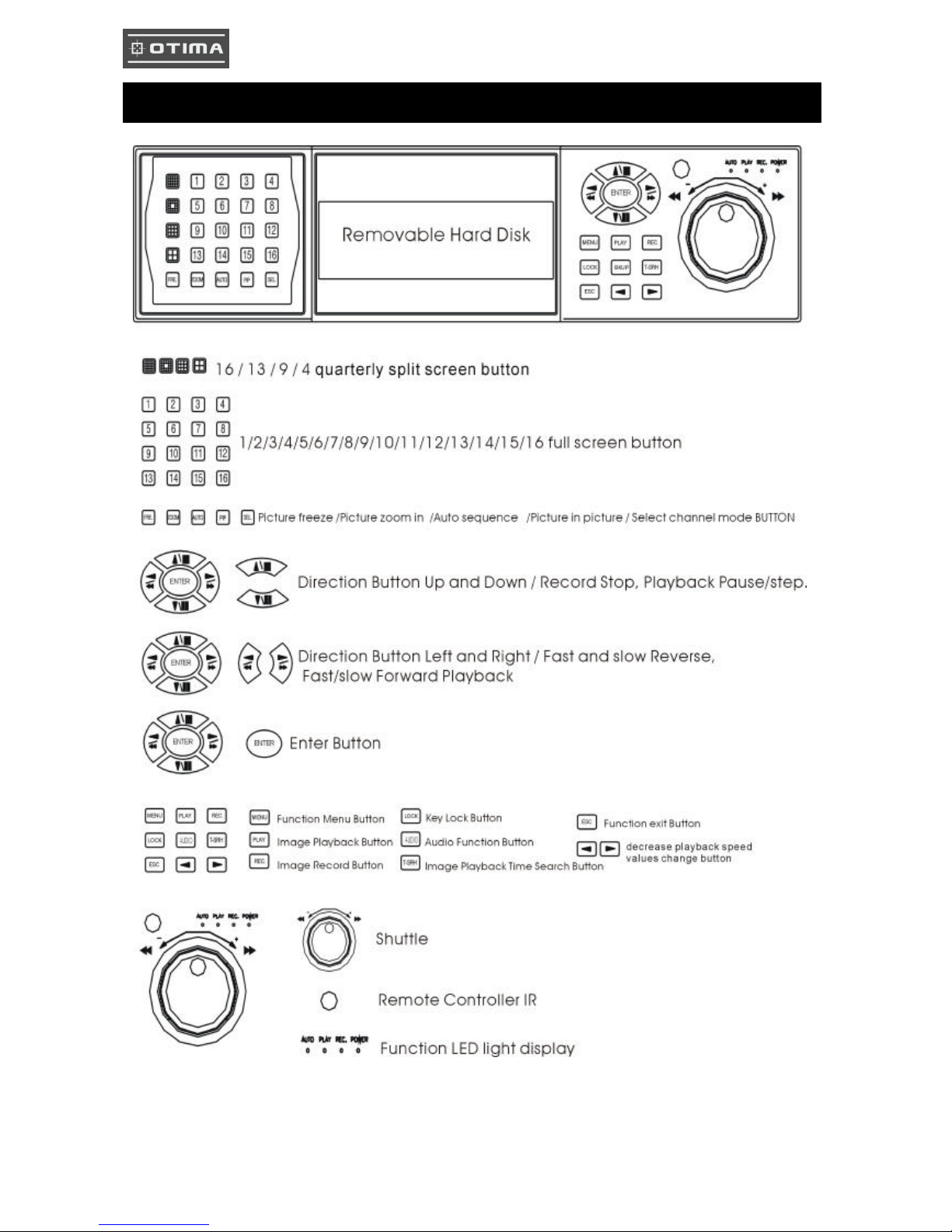
5
Unit Description of Front Panel
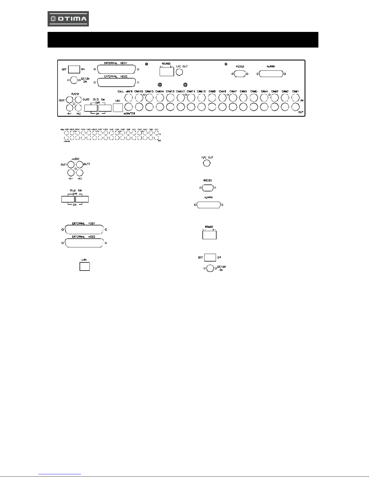
6
Unit Description of Rear Panel
16 Channel Video Input and
main/call monitor output
Audio Input. 2 Channel Input,
1 Channel Output (Out 1: Left, Out 2: Right)
Y/C video monitor output
75 Ohm High / Low Adjust
HDD BAY connector
RS 232 connector
Alarm connector
Control keyboard
connector
Network connector
Power In /
Power switcher
7
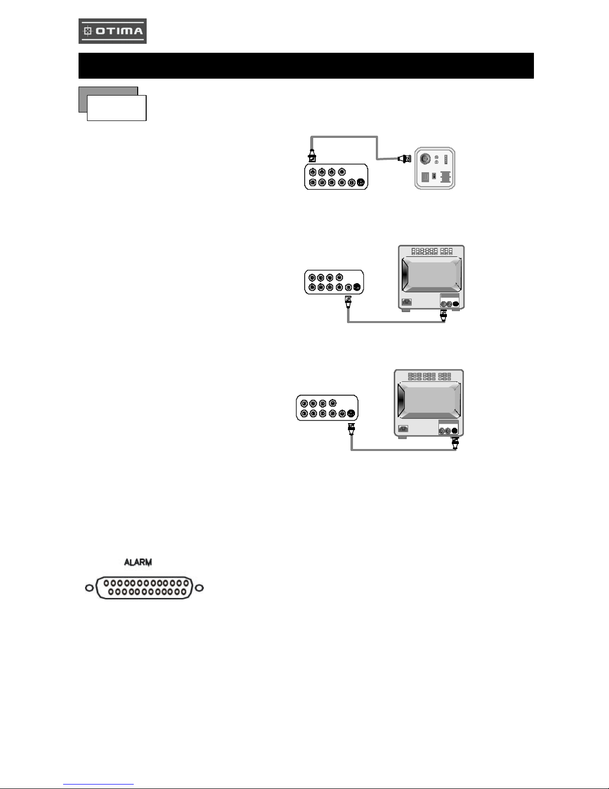
1) Camera Connection
Connect the camera to the CAMERA INPUT
on the Rear Panel of the 16 CH DVR.
2) Monitor Connection (Composite Connection
Method)
Connect the monitor to the MONITOR OUT on
the Rear Panel of the 16 CH DVR.
3) Monitor (S -VHS) Connection
Connect S-VIDEO Monitor to MONITOR OUT
(S-VHS) on the Rear Panel of the 16 CH DVR.
4) Sensor Connection
ALARM pin define.
13,12,11,10,9,8,7,6,5,4,3,2,1
25,24,23,22,21,20,19,18,17,16,15,14,13,12,11
Installation
Procedure
CH1 CH2 CH3 CH4
CH1 CH2 CH3 CH4
MONITOR
VIDEO
LENS
VIDEO
DC
AC24V/DC12
V.P
DC
LEVEL
Rear part of CAMERA
CH1 CH2 CH3 CH4
CH1 CH2 CH3 CH4
MONITOR
VIDEO A
IN OUT
CH1 CH2 CH3 CH4
CH1 CH2 CH3 CH4
MONITOR
VIDEO A
IN OUT
1.ALARM0 14. ALARM 13
2.ALARM1 15. ALARM 14
3.ALARM2 16. ALARM 15
4.ALARM3 17. ALARM COMM 2
5.ALARM4 18. DGND
6.ALARM5 19. DGND
7.ALARM6 20. DGND
8.ALARM7 21. ALARM NC 1
9. ALARM8 22. ALARM COMM 1
10.ALARM9 23. ALARM NO 1
11. ALARM10 24.ALARM NC 2
12.ALARM11 25. ALARM NO 2
13. ALARM12
8
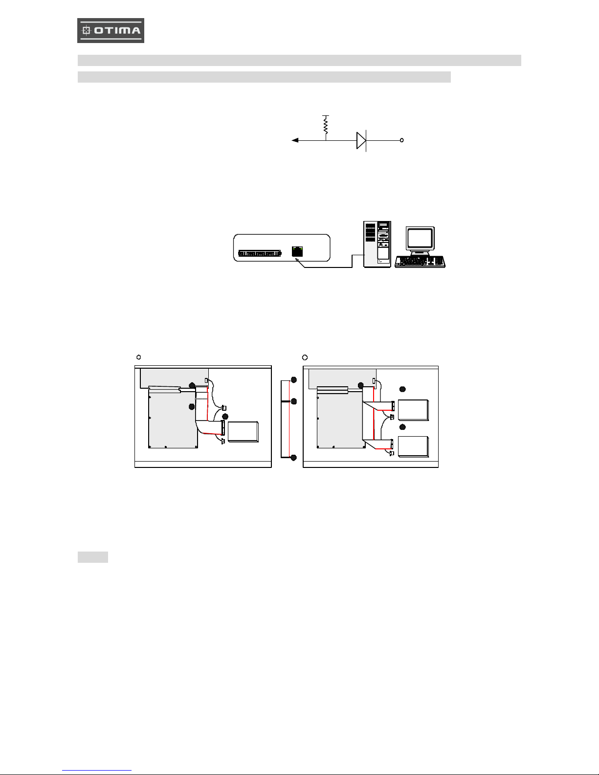
NOTICE: Sensor input is RECOGNIZED as LOW when alarm signal is on a level with GND, and it is
recognized as HIGH when ala rm signal is FLOATING or 5V. Following is internal circuit.
Thus, there is a danger of damage, when the sensor input goes to a Negative level or voltage higher than 5V.
5) Network Connection
DVR connects to LAN
◆To view video image on the computer through internet with DVR view software.
6) HDD connection
Notice:
-The 16 ch DVR provides 2 internal hard drives. We provide one hard disk drive with removable rack; the
other one is fixed designed.
-We recommend you to set the Removable Hard Disk as Slave. Set the other one as the Master.
Internal Circuit
1. Make sure the HDD is MASTER.
2. Make sure the cable connector is
correct.
3. MASTER set up, please check the
HDD panel.
1. Make sure the HDD is MASTER and
SLAVE.
2. Make sure the cable connector is correct.
3. MASTER and SLAVE set up, please check
the HDD panel.
rks
TERATRAY CONNECTION
ETHERNET
HDD
MASTER
MAIN BOARD
I/O BOARD
Set the drive jumpers as specified by hard disk drive manufacturer.
1
2
3
1
3
2
tie
HDD1
HDD2
MASTER
SLAVE
MAIN BOARD
I/O BOARD
Set the drive jumpers as specified by hard disk drive manufacturer.
2
1
3
1 How to connect single HDD 2 How to connect 2 HDD
D1
5
V

9
7) Power Connection
Connect the power to the POWER
CONNECTION on the Rear Panel of the
system, and turn on the switch.
8) Turn on the POWER.
Make sure the adaptor is 12V/5A.
9) Detail setup in SYSTEM SETUP
For detail setup, refer to the instruction of
SYSTEM SETUP.
1. +12VDC
2. +12VDC
3. +12VDC
4. RTN
5. RTN
6. RTN
4
2
1
536
10
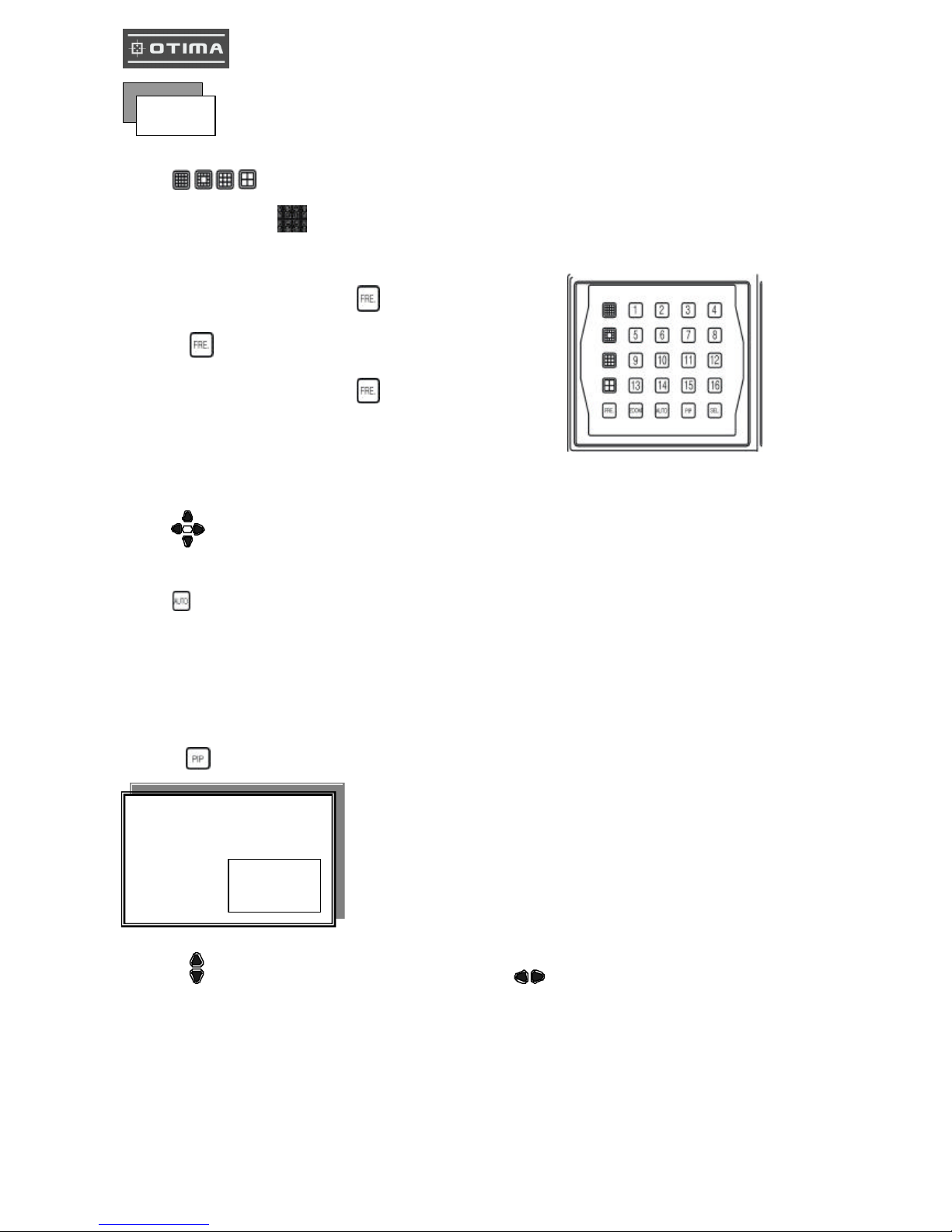
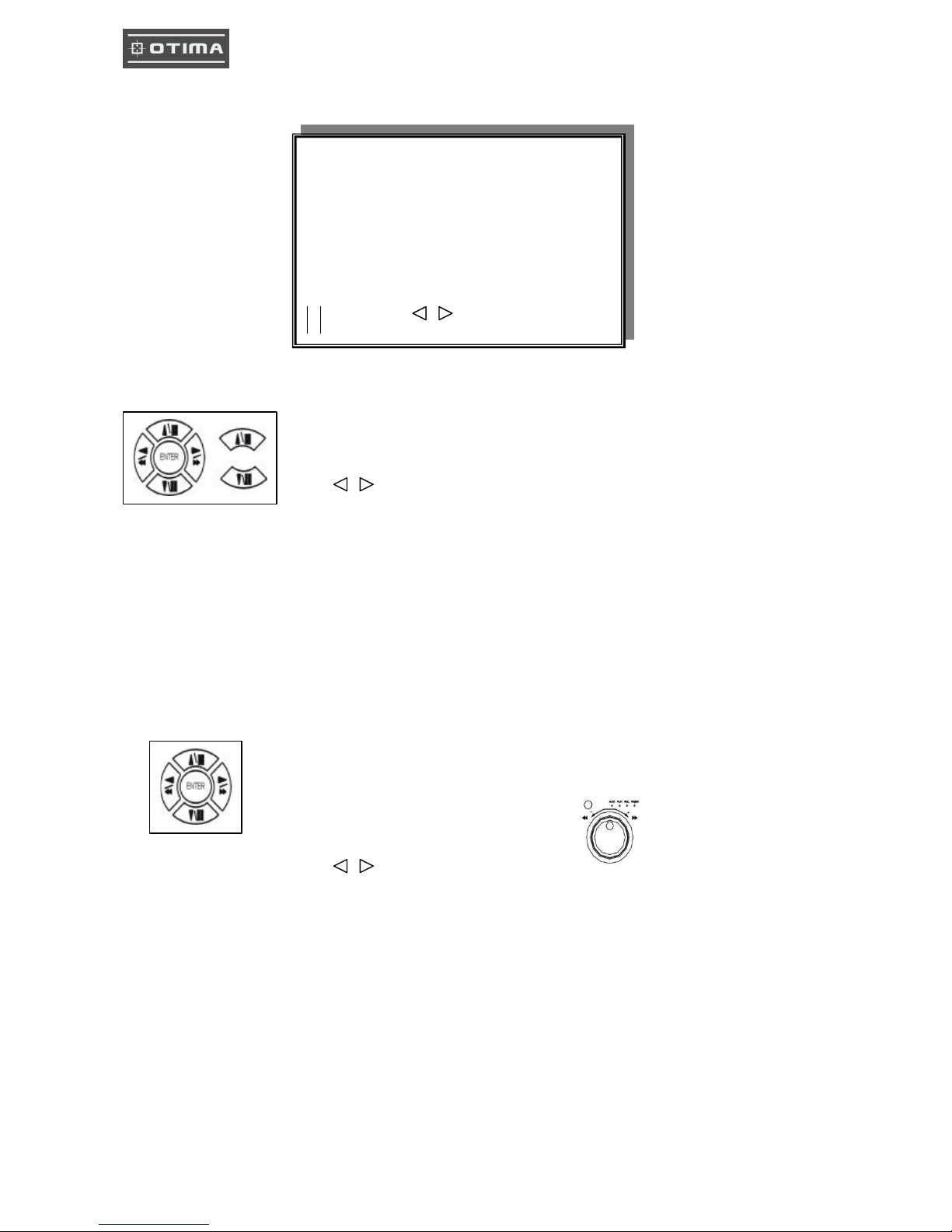
Full screen or quarterly split screen display
Press button, to display 16 / 13 / 9 / 4 quarterly split screen.
Press numeric buttons to display the desired camera image in full screen.
1.) FR EZZE Mode
1. In live and the quad mode press (FREEZE) button to freeze image.
Press again to cancel freeze mode.
2. On the full screen display, press (FREEZE) button to
freeze full screen image.
2.) Zoom Mode(Display Enlargement. )
Go to full screen mode with numeric buttons of live or playback
mode, then press ZOOM button to display screen Enlargement.
Use button to move position.
3.) Auto Mode
Press (AUTO) button begins to screen auto sequence.
>No auto sequence in 16 / 13 split screen.
>You could active auto sequence function in 9-split, 4-split, PIP or full-screen mode. The 3rd channels will
sequence in 9 split screen. 2nd channel do auto sequence in 4-split screen mode.
4.) PIP (PICTURE IN PICTURE)
1.) Press (PIP) button.
2) With button, select the main channel screen, press button to select desired camera channel in
small screen.
Main picture
Sub picture
Picture
11
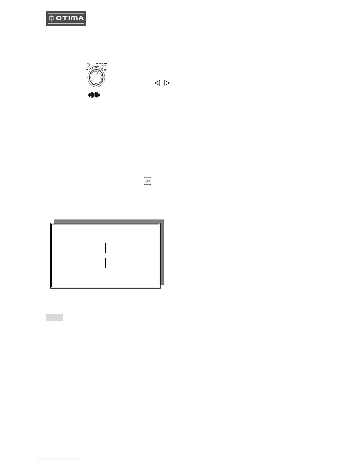
5.) SEL (Select)
>On the 13 / 9 / 4 split screen, press SEL can change the each channel order.
- Press SEL button to active the selection function.
- Turn the inner-shuttle or button to select the desired camera channel in split-1.
- Press change button to change the split-screen position.
- Press SEL button again to cancel the selection function.
6.) Alarm Sensor Recording
>See the alarm recording setup page
7.) Scheduled Recording
>See the scheduled recording setup page
8.) Motion detection Recording
See the motion detection recording setup page
9.) Key Lock function
On the Live or Playback mode, press (lock),
Only, numeric, freeze, auto, pip, and zoom buttons could work. Press lock key again to enter the login-in
window. Enter admin or user password to unlock.
10.) AUDIO BUTTON
Notice
1> Recording is stopped during playback.
2> Recording is not possible if no camera is connected.
3> DVR must be not on the PLAY mode, if user wants to remote view in the Internet.
AUDIO CONTROL
CH +
CH -
VOL -
VOL +
CH: choose which audio channel output
VOL: Audio volume values change.

12
1. Playback Mode
1) Press button to begin playback. (System will playback the images in backward)
2. T-SRH button
1) T-SRH: Playback by time search.
Press T-SRH button to active playback function.
2) EVENT LIST (Alarm List): Event source - Video loss/ alarm trigger
PLAY: User press direction button to choose items, then press ENTER to start playback.
SORT: DATE, alarm events sort by date and time. CH, alarm events sort by channel.
TYPE, alarm events sort by type.
Press (SEL) button to change sort.
DELETE: ITEM -delete items by each. PAGE-delete each page. ALL-delete all items.
Playback
PLAY
PLAY SETUP PAGE
EVENT LIST
TIME LIST
PLAY END: RECYCLE
FIRST: xxxx/xx/xx xx:xx:xx
LAST: xxxx/xx/xx xx:xx:xx
GOTO: xxxx/xx/xx xx:xx:xx
PLAY GOTO TIME
OCCURRED TIME CH TYPE
PLAY SORT: DATE DELETE: ITEM
: MOVE, : PAGE, ENTER: PLAY
Press direction button UP/DOWN to choose items.
Press direction buttons
LEFT/RIGHT to choose mode. (PLAY / SORT / DELETE)
Press values change button to change page.
Press direction button
UP/DOWN to choose
items.
13
3) TIME LIST (Playback image by Time -Search): Recorded images list (by hours)
No items or page display limit. Items. DVR recording mode is continued.
4) PLAY END: After image playback end, DVR is going to RECYCLE (continue playback) /
RECORD (continue record) / STOP (stop record or playback)
5) FIRST: xxxx/xx/xx xx:xx:xx (The FIRST date and time recording display).
If hard disk has recycled record, the first date and time display would different.
6) LAST: xxxx/xx/xx xx:xx:xx (The final date and time recording display ).
When user stop record / or go to menu, at that moment is the last record.
7) GOTO: xxxx/xx/xx xx:xx:xx (year / month / day, Hour / Minute / Second)
Press values change button or turn inner-shuttle to change date
and time values.
8) PLAY GOTO TIME
After date and time input, direction move to PLAY GOTO TIME, press ENTER to start playback.
TIME SEARCH LIST PAGE
: CURSOR, : PAGE, ENTER: PLAY
Press direction button UP/ DOWN to choose items.
Press values change button to change to next page.
Press direction button Left/Right to change date and time values position.
14
1) Press
MENU
button to enter into menu. You could do the system function setup in MENU.
2) Password enter window pop-up:
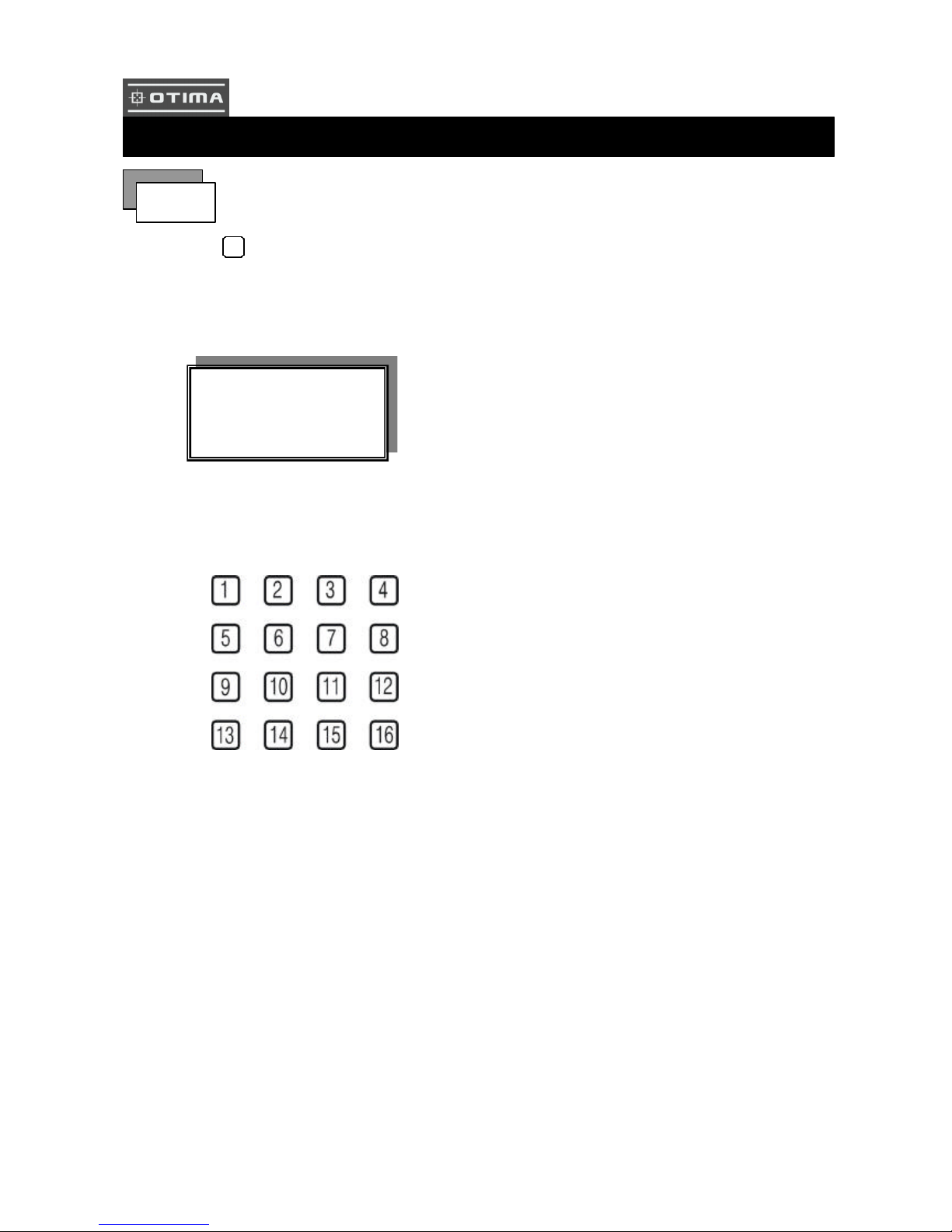
3) Press numeric button to choose password then menu pop-up.
4) Remote controller function buttons are same as DVR panel function buttons.
LOGIN
1. Password (Account-Admin) : 44444
2. Password (Account-User) : 11111
FUNCTION SETUP
LOGIN DVR SYSTEM
PASSWORD xxxxx
15
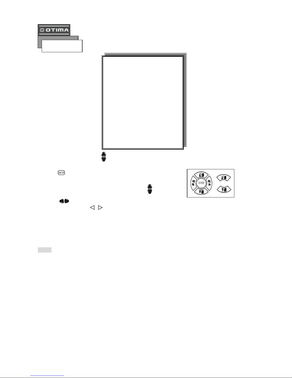
Press MENU button to enter MAIN SETUP PAGE.
1) Use direction button up/down button to select setup item.
2) Press button to enter into sub-menu function setup.
3) Press sub-menu item with direction button up/down
or left/right button.
And change the value with values change button or turn inner-shuttle.
4) Press ESC to go back to main menu or exit menu.
Notice:
1. ADMIN level can setup all menu functions.
2. USER level cannot setup ADVANCED page.
Basic Operation
MAIN SETUP PAGE
1. HDD INFORMATION
2. DATE -TIME SETUP
3. DISPLAY SETUP
4. CAMERA SETUP
5. BUZZER SETUP
6. AUDIO SETUP
7. SYSTEM SETUP
8. ADVANCED SETUP
MENU, ESC: EXIT, ENTER: RUN
16
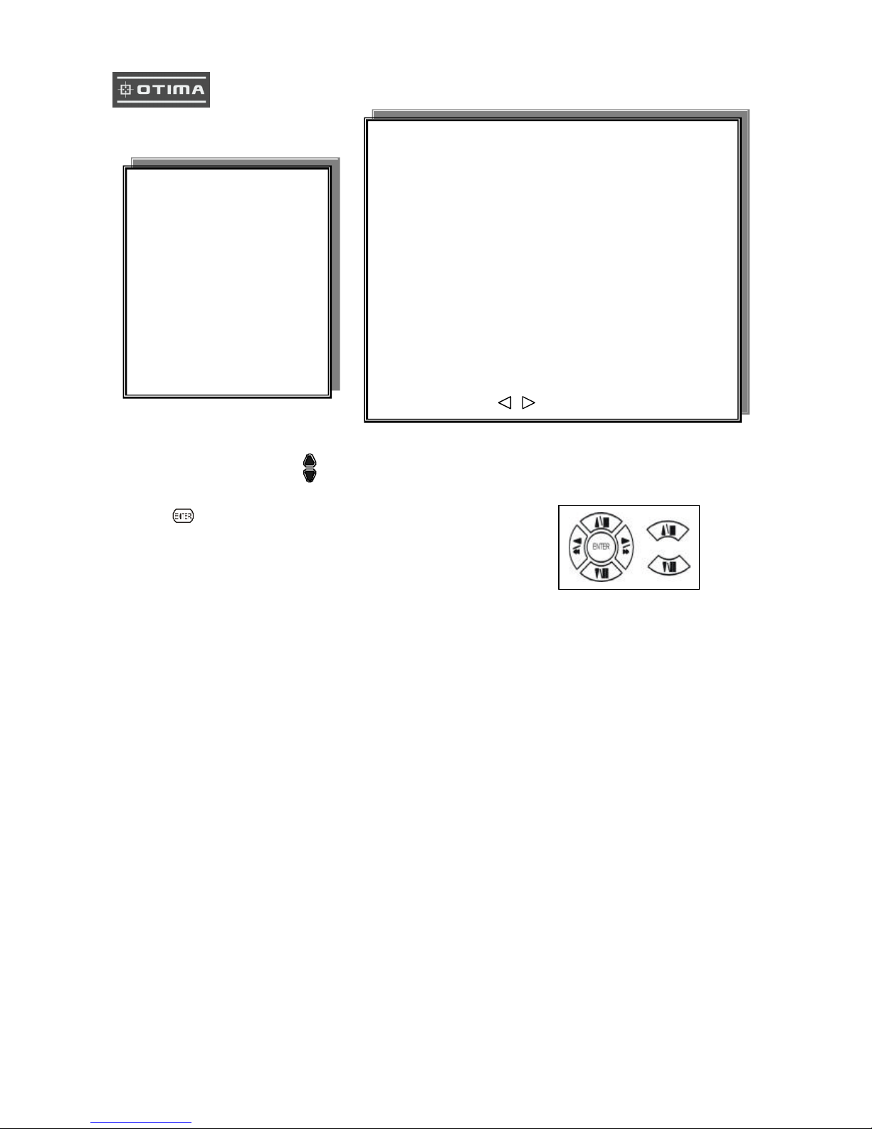
1. HDD INFORMATION
1) Use direction button up/down button to select HDD INFORMATION item position.
2) Press button to enter sub-menu of
HDD INFORMATION item
3) Press ESC to go back to main menu or exit menu.
- 5 items per each page. All is two pages. Total is 10 items. 01~10.
Information display is Number, Size, Used, Brand, POS.
>Number: First page: 01~05 items. Second page: 06~10 items.
>Size: Hard disk capacity display. xxGB. >No hard disk capacity install limit.
>Brand: DVR system auto detect hard disk brand after power on.
>Position: IN-DVR / RACK -1/RACK-2/RACK-3/RACK-4/RACK-5
-Status: PARTIAL
-Frame: Hard disk total image frame rate display.
-Start: The first recording date and time display.
-End: The last recording date and time display.
MAIN SETUP PAGE
1. HDD INFORMATION
2. DATE -TIME SETUP
3. DISPLAY SETUP
4. CAMERA SETUP
5. BUZZER SETUP
6. AUDIO SETUP
7. SYSTEM SETUP
8. ADVANCED SETUP
NO. SIZE USED BRAND POS
01 xxxxxxxxxxxxxxxxxxxxxxxxxxxxxx
02 xxxxxxxxxxxxxxxxxxxxxxxxxxxxxx
03 xxxxxxxxxxxxxxxxxxxxxxxxxxxxxx
04 xxxxxxxxxxxxxxxxxxxxxxxxxxxxxx
05 xxxxxxxxxxxxxxxxxxxxxxxxxxxxxx
STATUS: PARTIAL
FRAME:
START:
END:
MENU, ESC: EXIT, :PAGE
 Loading...