

Otima DVR-0420TF User Manual

1
Thank you for purchasing our product.
Please read this User’s Manual before
using the product. Change without Notice
4 Channel Digital Video Recorder
User’s Manual
2
CAUTION
RISK OF ELECTRICAL
SHOCK. DO NOT OPEN !
CAUTION: TO REDUCE THE RISK OF ELECTRICAL SHOCK,
DO NOT REM OVE COVER (OR B ACK), NO USER
SERVI CEAB LE PARTS REFER SERVICING TO
QUALIFIE D SERVICE PERSONNEL.
This label may appear on the bottom of the unit due to space limitations.
Safety Precautions
The lightning flash with arrowhead symbol, within an equilateral
triangle, is intended to alert the user to the presence of insulated
dangerous Voltage within the product’s enclosure that may be
sufficient magnitude to constitute risk of electrical shock to persons.
The exclamation point within an equilateral triangle is intended to alert
the user to the presence of important operation and maintenance
(servicing) instructions in the literature accompanying the appliance.
WARNING: TO PREVENT FIRE OR SHOCK HAZARD, DO NOT
EXPOSE UNITS NOT SPECIFICALLY DESIGNED FOR
A
ttention: installation should be performed by qualified service
Personnel only in accordance with the National Electrical Code or
applicable local codes.
Power Disconnect. Units with or without ON-OFF switches have
power supplied to the unit whenever the power cord is inserted into
the power source; however, the unit is operational only when the
ON-OFF switch is the ON position. The power cord is the main power
disconnect for all unites.
“CAUTION: Danger of explosion if battery is incorrectly replaced.
Replace only with the same or equivalent type recommended by the
manufacturer. Dispose of used batteries according to the
manufacturer‘s instruction.”
During the warranty period (one year), we will repair or replace the
DVR free of charge.
Be sure to have the model number, serial number and vendor stick on
hard disk for service representative.
Warranty
and Service

3
Before installing stand alone DVR, be sure to thoroughly review and follow the instructions in this Users
Manual. Pay particular attention to the parts that are marked NOTICE.
Also, when connecting with external application, first turn the power OFF and follow manual
instruction for appropriate installation.
1. This document is intended for both the administrator and users of stand alone DVR Model.
2. This manual contains information for configuring, managing and using stand alone DVR Model.
3. To prevent fire or electrical shock, do not expose the product to heat or moisture
4. Be sure to read this manual before using stand alone DVR Model.
5. For questions and technical assistance of this product, contact your local dealer.
►Strong recommendation on installation of the DVR unit
1. Check electricity at the place you want to install the DVR unit is stable and meets our electricity
requirements.
Unstable electricity will cause malfunction of the unit or give critical damage to the unit.
2. Several chips on the main board of the DVR unit and hard disk drive inside the unit generate heat,
and it must be properly discharged.
Do not put any objects just beside exhaust port(fan) on the left side of the unit and do not close up an
opening (fresh air in-take) on the right side of the unit..
3. Put the DVR unit at well-ventilated place and do not put heat-generating objects on the unit.
When it is installed inside 19 inch mounting rack together with other devices, please check built-in
ventilation fan of the rack is properly running.
About this document
Before reading this document
4
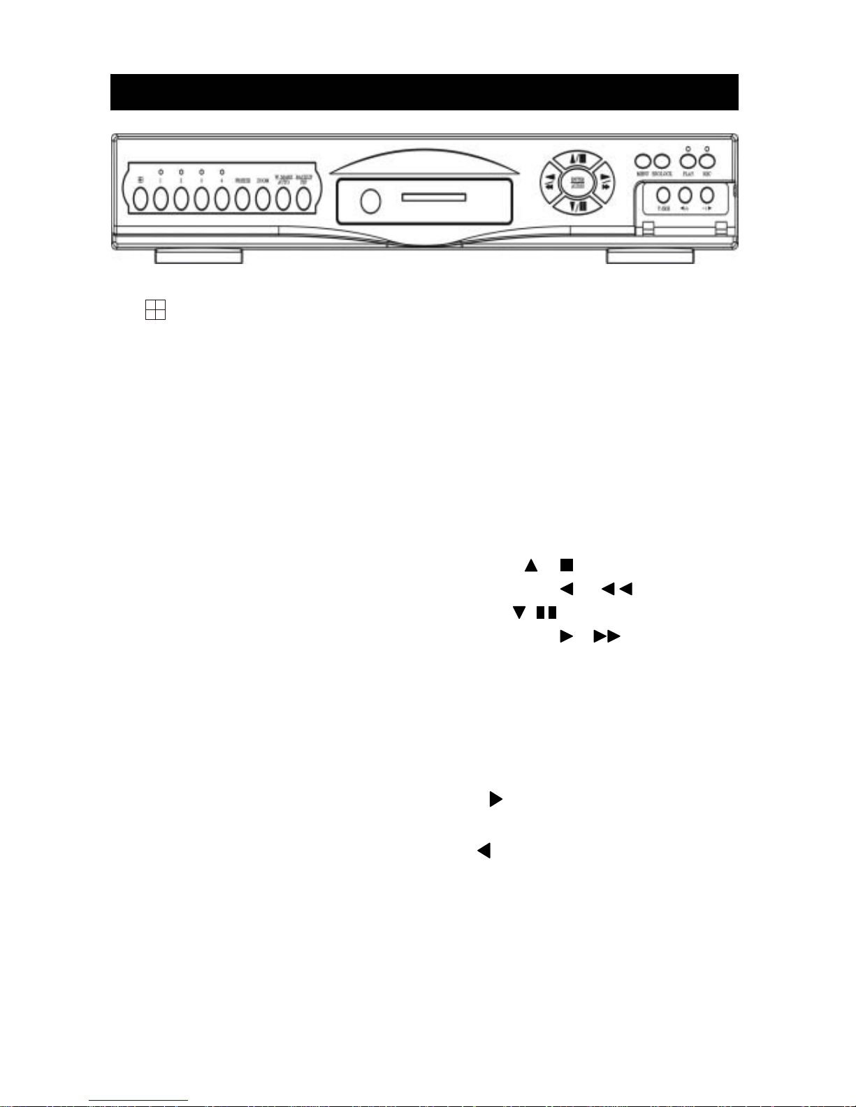
1. : 4 quad screen mode button / Mode function key / 4 or 9 split display on playback mode
2. CHANNEL 1 : Channel 1 full screen button
3. CHANNEL 2 : Channel 2 full screen button
4. CHANNEL 3 : Channel 3 full screen button
5. CHANNEL 4 : Channel 4 full screen button
6. FREEZE : Picture freeze mode button
7. ZOOM : Picture zoom x2 mode button
8. AUTO / W.MARK : Auto sequence mode / Water Mark function button.
9. PIP / BACKUP : Picture in picture mode button / Image backup button
10. UP / STOP : Direction button UP / Playback stop button /
11. REW : Reverse playback choose button / Still playback /
12. DOWN / PAUSE : Direction button down / Playback pause /
13. FF : Forward playback choose button / Still playback /
14. ENTER / AUDIO : Sub-menu enter button / Audio on or off button
15. MENU BUTTON : Press this button to display the menu setup
16. ESC/LOCK : Press this button to Key Lock function / Sub-MENU exit button
17. T-SRH : Press this button to playback time search
18. PLAY BUTTON : Press this button to playback
19. DIRECTION BUTTON : Playback speed choose. (Increase) or values change.
20. REC BUTTON : Press this button to start recording image
21. DIRECTION BUTTON : Playback speed choose.(reduce) or values change.
22. CF Card Slot : Compact Flash Card insert
Unit Description of Front Panel
5
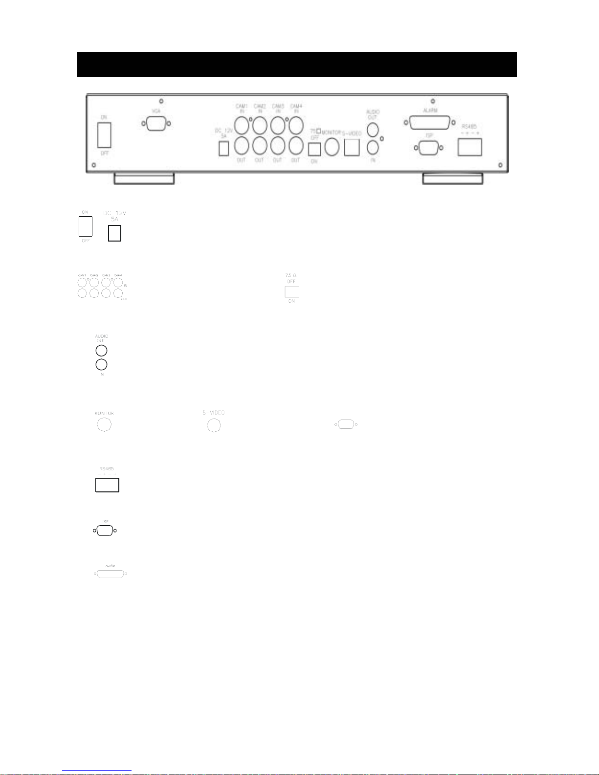
Unit Description of Rear Panel
Power code in 12V/5A, power switcher (ON / OFF)
Camera 1 ~ 4 in and
looping out
Audio channel input x 1 and output x 1
75 Ohm ON/OFF (high/low adjust)
Monitor out
S-Video (Y/C) monitor
RS-485 control keyboard connector
RS-232 connector (ISP. Firmware upgrade port)
Alarm connector
VGA
VGA output. PC monitor connector.
(Not available)
6
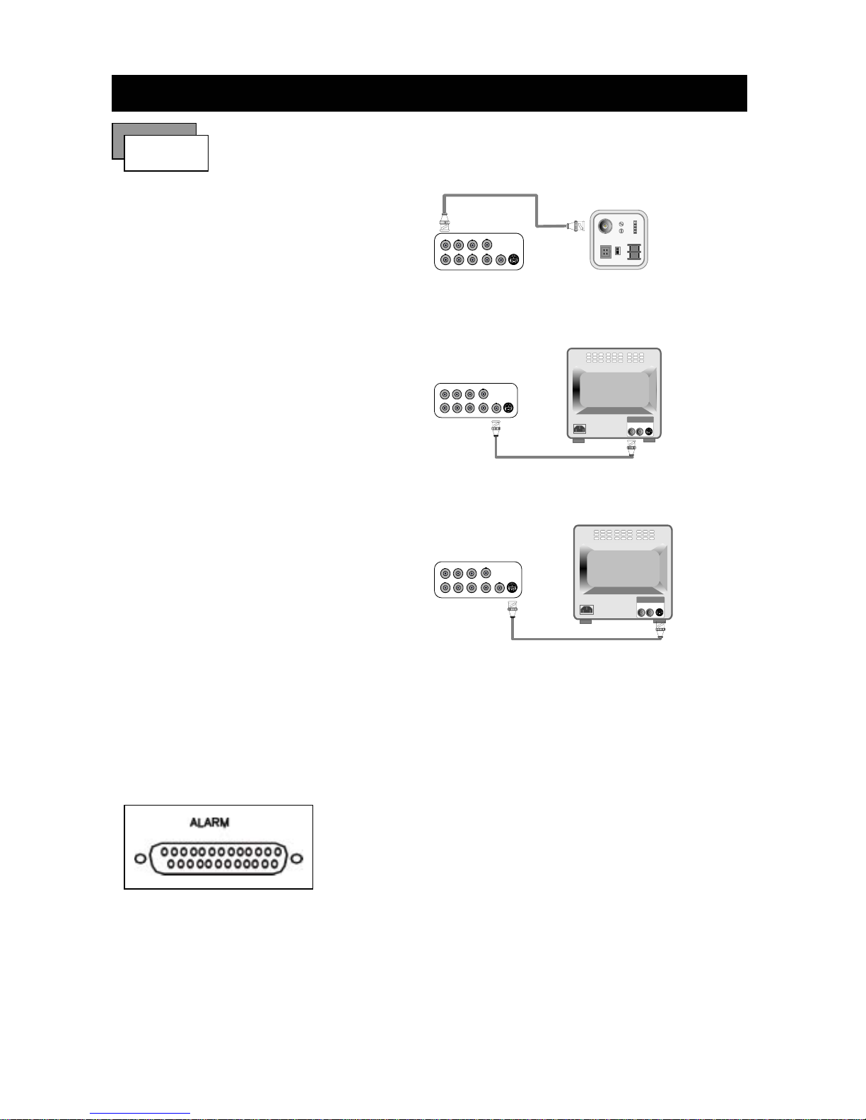
1) Camera Connection
Connect the camera to the CAMERA INPUT
on the Rear Panel of the 4 CH DVR.
2) Monitor Connection (Composite Connection
Method)
Connect the monitor to the MONITOR OUT on
the Rear Panel of the 4 CH DVR.
3) Monitor Connection
Connect S-VIDEO Monitor to MONITOR OUT
on the Rear Panel of the 4 CH DVR.
4) Sensor Connection
Connect the Sensor to the SENSOR INPUT/
OUTPUT on the Rear Panel of the system
13,12,11,10,9,8,7,6,5,4,3,2,1
25,24,23,22,21,20,19,18,17,16,15,14
◆Relay output : COM+NC, COM+NO
◆Alarm input : Short-circuit between Alarm0, Alarm1, Alarm2 or Alarm3 and GND is recognized as
alarm by default.Alarm0~3 will be corresponding to Camera1~4.
Installation
Procedure
CH1 CH2 CH3
CH4
CH1 CH2 CH3 CH4
MONITOR
VIDEO
LENS
VIDEO
DC
AC24V/DC12
V.P
DC
LEVEL
Rear part of CAMERA
CH1 CH2 CH3
CH4
CH1 CH2 CH3 CH4
MONITOR
VIDEO A
IN OUT
CH1 CH2 CH3
CH4
CH1 CH2 CH3 CH4
MONITOR
VIDEO A
IN OUT
1.ALARM0
2.ALARM1
3.ALARM2
4.ALARM3
23.ALARM NC
24.ALARM NO
25.ALARM COM
5. ~ 19. GND
7
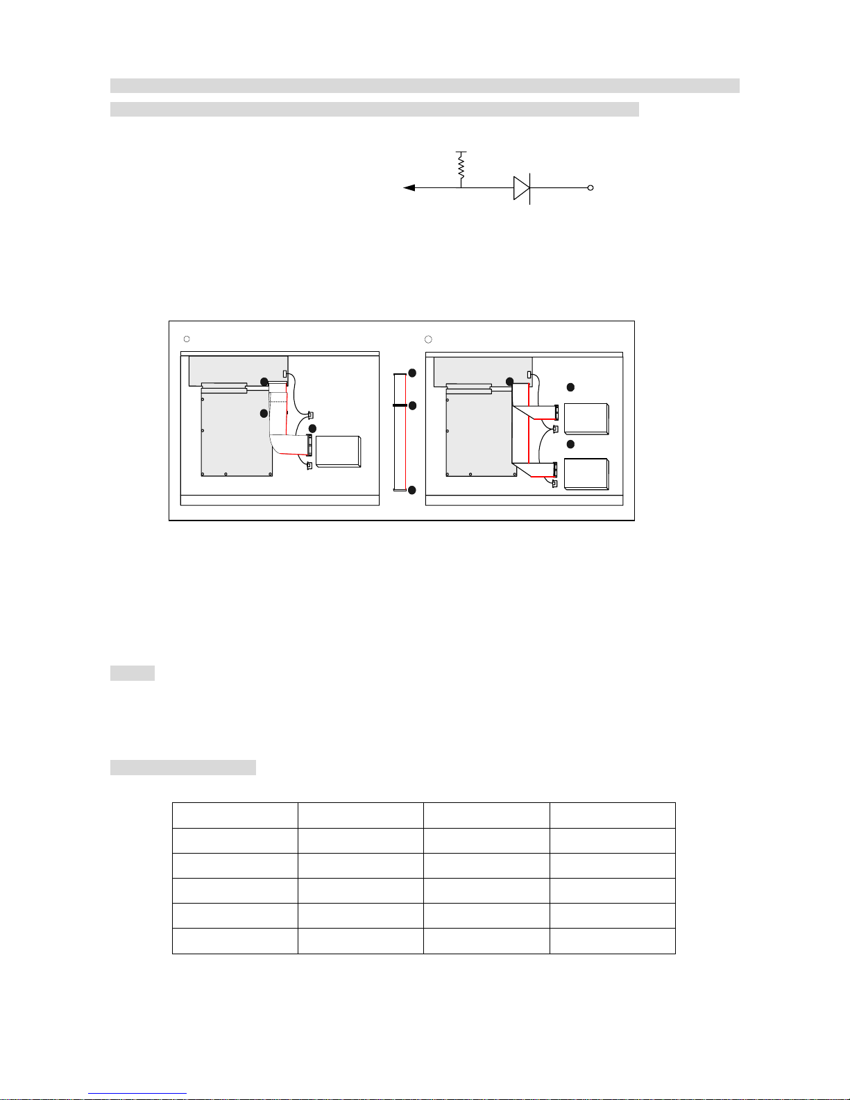
NOTICE: Sensor input is RECOGNIZED as LOW when alarm signal is on a level with GND, and it is
recognized as HIGH when alarm signal is FLOATING or 5V. Following is internal circuit.
Thus, there is a danger of damage, when the sensor input goes to a Negative level or voltage higher than 5V.
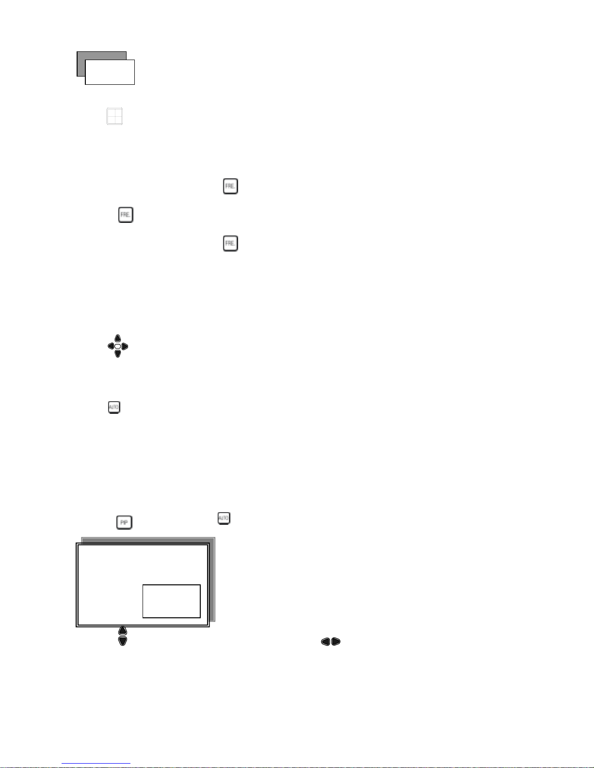
5) HDD connection
Notice:
-The 4 CH DVR capable of accomeudating maximum 2 internal hard drives.
-Hard Disk Master and Slave jumper pin must be set correctly, otherwise it makes DVR react faulty.
Hard Disk testing table:
Brand Model Capacity Notice
Seagate Barracuda 80 GB
IBM DeskStar 80 GB
WD2000 Caviar 200 GB
Hitachi DeskStar 80 GB
Maxtor MaxLineII 300 GB
Internal Circuit
1. Make sure the HDD is MASTER.
2. Make sure the cable connector is
correct.
3. Please check the HDD panel for
Master set up.
1. Make sure the HDD is MASTER and
SLAVE.
2. Make sure the cable connector is
correct.
3. Please check the HDD panel for
Master and Slave set up.
HDD
MASTER
MAIN BOARD
I/O BOARD
Set the drive jumpers as specified by hard disk drive manufacturer.
1
2
3
1
3
2
tie
HDD1
HDD2
MASTER
SLAVE
MAIN BOARD
I/O BOARD
Set the drive jumpers as specified by hard disk drive manufac turer.
2
1
3
1
How to connect single HDD 2 How to connect 2 HDD
D1
5
V
8
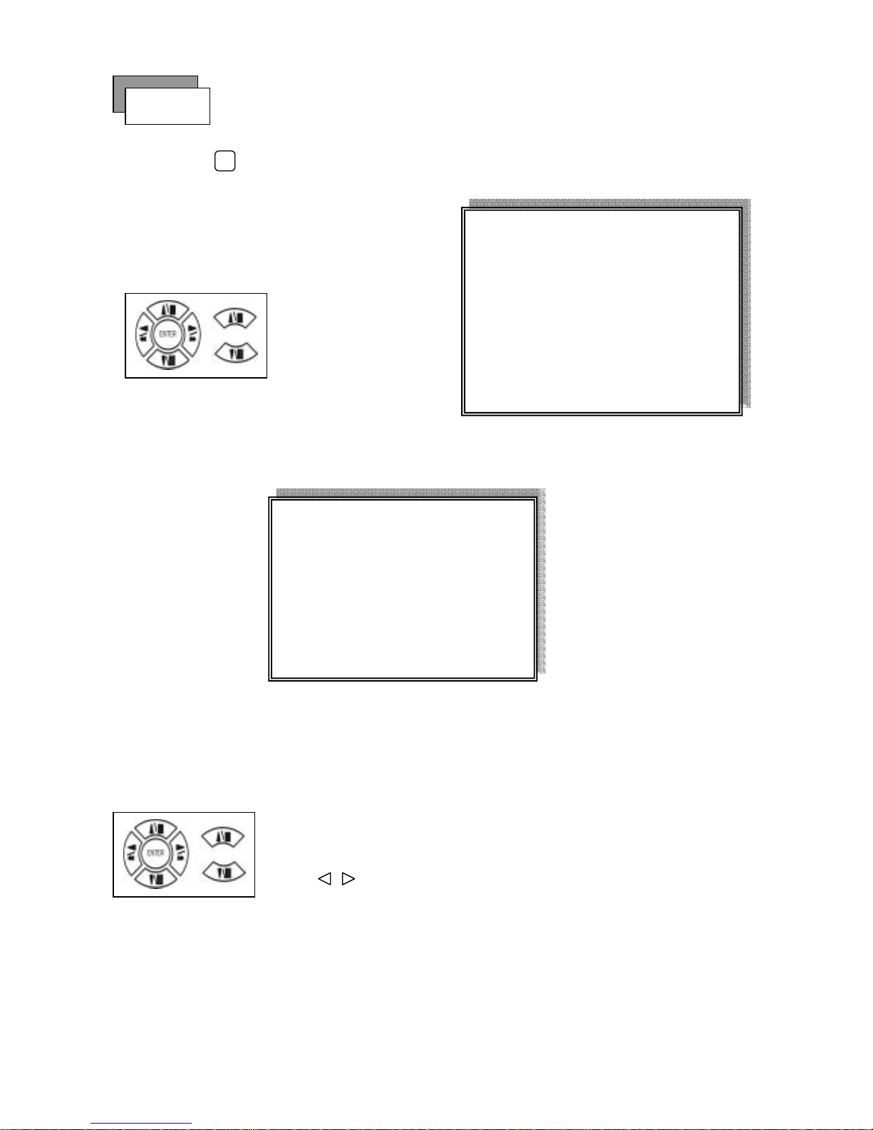
Full screen or quad screen display
Press
quad button to display 4 quad screen.
Press numeric 1 / 2 / 3 / 4 buttons to display a desired camera image in full screen.
1.) FREEZE Mode
1. In live and the quad mode press (FREEZE) button to freeze image.
Press
again to cancel freeze mode.
2. On the full screen display, press (FREEZE) button to
freeze full screen image.
2.) Zoom Mode(Display Enlargement.)
Go to full screen mode with numeric buttons at live or playback
mode, then press ZOOM button to display screen Enlargement.
Use
button to move position.
3.) Auto Mode
Press (AUTO) button to start screen auto sequencing, and press it again to cancel auto mode.
4.) W.MARK. Water Mark mode.
Water Mark protection function on or off. To prevent hacker using special software to modify the image data.
System SetupÆWatermark Check mode On. Press W.Mark button to on or off. (Playback mode only)
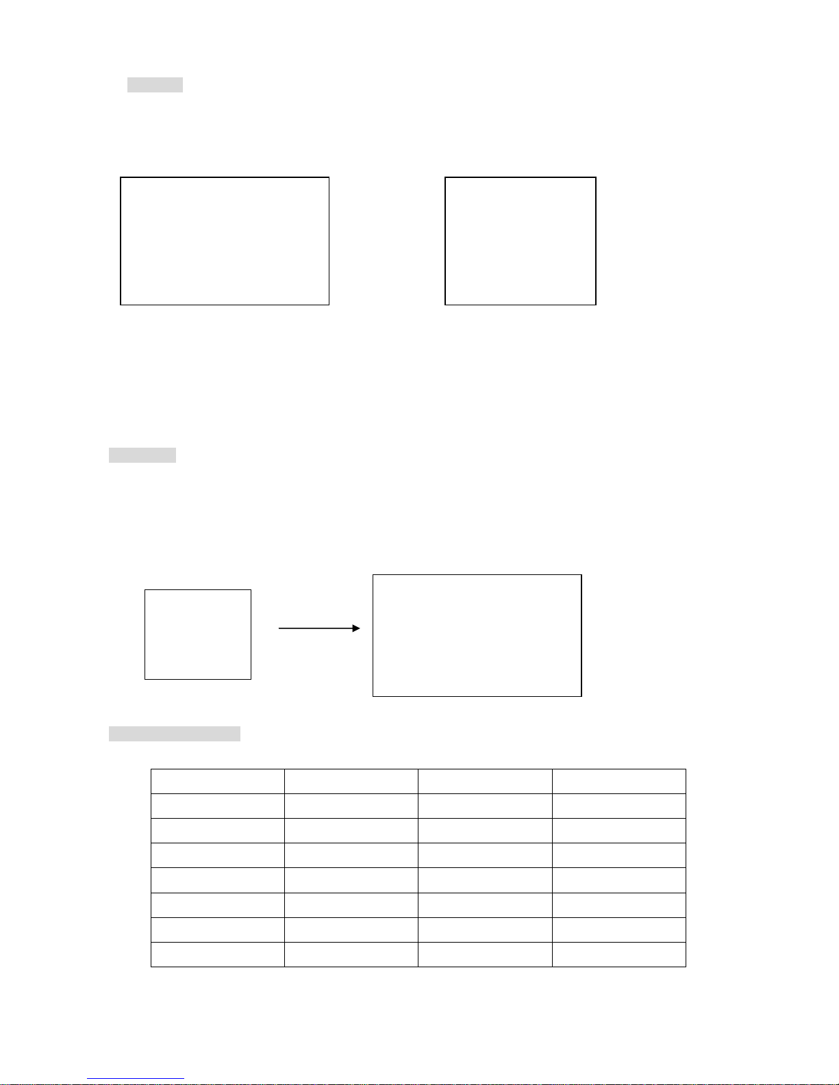
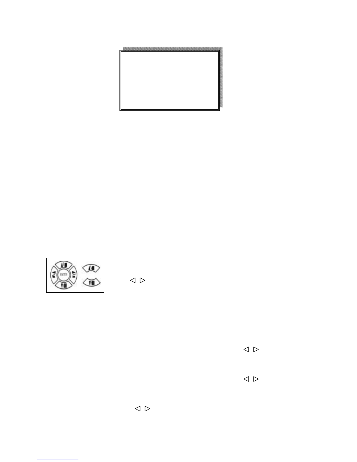
5.) PIP (PICTURE IN PICTURE)
1.) Press (PIP) button. Press
(AUTO) button to start sub-screen auto sequencing.
2) With button, select the main channel screen, press button to select desired camera channel in
small screen.
Main picture
Sub picture
Picture
9
6.) BACKUP / PIP. Image backup mode.(Image back up must be done on playback mode only.)
Locate the playback point of which you want. Press BACKUP, the BACKUP CAUTION window pop-up. Press
ENTER to begin data back up. Capacity of CF card is not limit, but the maximum capacity display is 9999MB.
On playback mode, presses BACKUP: Lower-Right corner of the screen:
0000M / 0256 (Presently back up progress / Total capacity of CF card)
Important:
If the CF card contains old data, please format CF card to FAT or FAT 32 on computer before insert to DVR
CF card slot. Otherwise, DVR would not detect correct CF card format. Any brand of CF card is acceptable.
Additional:
During playback, CF card is full or user press BACKUP button screen display a “PAUSE” caption, User takes
out the CF to computer USB slot then save data to hard disk. After, re- insert CF card to DVR slot, user press
BACKUP again. Press ENTER to continue backup or backup button to cancel.
CF card testing table:
Brand Model Capacity Notice
Cannon FC-8M 8 MB
PQI 32/128 MB
Nikon 16 MB
KingMax 16 MB
Apacer 1 GB
Sandisk F1 x24 512 MB
Transcend F1 x45 256 MB
** BACKUP CAUTION **
ALL DATA IN THE CF CARD
WILL BE CLEARED.
PRESS [ENTER] TO BACKUP.
PRESS [BACKUP] TO CANCLE.
0000M / 0256M
PAUSE
** BACKUP CAUTION **
ALL DATA IN THE CF CARD
WILL BE CLEARED.
PRESS [ENTER] TO BACKUP.
PRESS [BACKUP] TO CANCEL.
10
7.) Alarm Sensor Recording
>See the alarm recording setup page
8.) Scheduled Recording
>See the scheduled recording setup page
9.) Motion detection Recording
>See the motion detection recording setup page
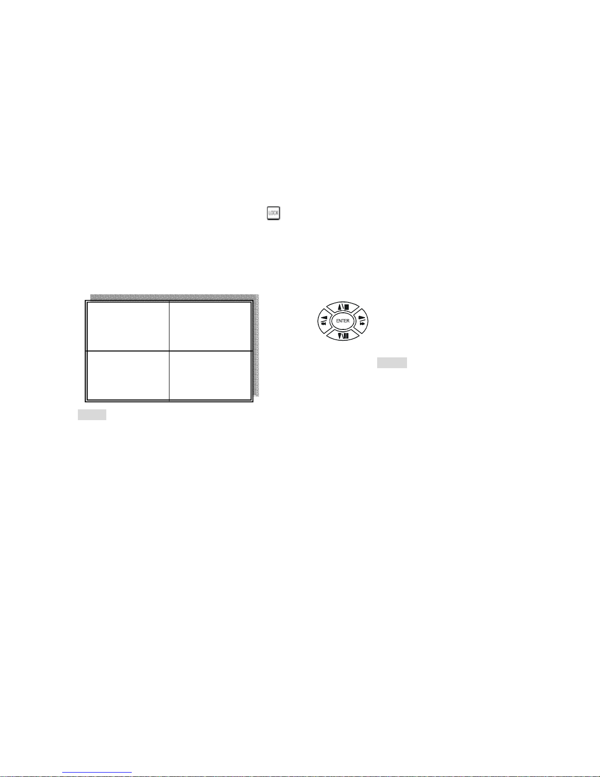
10.) Key Lock function
>On the Live or Playback mode, press (lock), Only, numeric, freeze, auto, pip, and zoom buttons
could work. Press lock key again to enter the login-in window. Enter admin or user password to unlock. Key
lock function only accept password correct log in even re-boot DVR power.
11.) AUDIO function ))))
Notice
Audio playback only on normal( x 1 ) playback.
Audio playback: Press AUDIO / ENTER,
)))))displays on the Upper-left of screen. At that time, audio
will playback. Press it again to turn it off.
)))) xxxxxxxxx
11
1. Playback Mode
1) Press button to begin playback. (System playback the images backward)
2. T-SRH button
1) T-SRH: Playback by time search.
Press T-SRH button to active playback function.
1) TIME LIST (Playback image by Time-Search): Recorded images list (by hours)
Y / M / D H / M (Beginning of recording time) Y / M / D H / M (End of recording time)
Every playback data list displays by an hour.
No page display limit. 10 items display on each page.
Playback
PLAY
MAIN PLAY PAGE
1.MASTER TIME LIST
2.SLAVE TIME LIST
3.MASTER EVENT LIST
4.SLAVE EVENT LIST
5.GOTO DATE: 2004/12/31
6.GOTO TIME: 12:12
7.GOTO PLAY
Press direction button
UP/DOWN to choose
items.
TIME LIST
Y / M / D H / M Y / M / D H / M
Press direction button UP/DOWN to choose items.
Press values change button to change to previous / next page.
12
2) EVENT LIST (Alarm List): Event source- Video loss / Alarm trigger / Motion / Record
10 items display on each page / Total 5000 items display for 500 pages. When event list is out of compass,
the total items are less then 5000.
Y / M / D H / M : Year / Month / Day Hour / Minute
>Event happens time.
_ _ _ _: Event Channel Display.
>1 CH, 2 CH, 3 CH, 4 CH.
Motion: Event type.
>Includes Motion / Alarm / V-Loss / Record
>Special time search playback:
Go TO DATE:20021212
-Choose year / month / day
>Press direction button Left / Right to choose items, press values change button to change value.
GOTO TIME:12:12
-Choose hour and minute
>Press direction button Left / Right to choose items, press values change button to change value.
GOTO PLAY
-Press ENTER button to start playback.
Notice: Playback speed change by . Speed is x 1, x 2, x 4, x 8, x 16.
Press direction button UP/DOWN to choose items.
Press values change button to change page. Press ENTER to start
playback.
EVENT LIST
NO Y / M / D H / M _ _ _ _ Motion

13
1) Press
MENU
button to enter into menu. You could do the system function setup in MENU.
2) Password enter window pop-up:
3) Press numeric (1 ~ 4 )button or remote controller ( 0 ~ 9 )to choose password.
4) Remote controller function buttons are same as DVR panel function buttons.
LOGIN
Default password (Account-Admin) : 44444
Def a ult p asswo rd (Ac c ount - User) : 11111
FUNCTION SETUP
CHECK PASSWORD MENU
PASSWORD (*****)
14
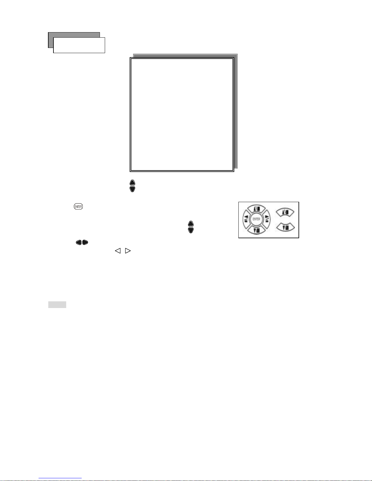
Press MENU button to enter MAIN SETUP PAGE.
1) Use direction button up/down
button to select setup item.
2) Press
button to enter into sub-menu function setup.
3) Press sub-menu item with direction button up/down
or left/right
button.
And change the value with values change button or turn inner-shuttle.
4) Press ESC to go back to main / sub menu or exit menu.
Notice:
1. ADMIN level can setup all DVR menu functions.
2. USER level cannot setup ADVANCED page of DVR main menu function.
Basic Operation
MAIN SETUP PAGE
1. HDD INFORMATION
2. DATE-TIME SETUP
3. DISPLAY SETUP
4. CAMERA SETUP
5. BUZZER
SETUP
6. SYSTEM SETUP
7. ADVANCED SETUP
MENU, ESC: EXIT, ENTER: RUN

15
1. HDD INFORMATION
- 2 hard disk information display.
Information display: POSITION SIZE USED BRAND
>POSITON: Master / Slave
>SIZE: Hard Disk capacity. xxGB. Maximum display is 999MB
>USED: 00 ~ 100 %. Hard disk overwrites always on 100 %.
>BRAND: DVR auto detect hard disk brand.
>LAST TIME: The last record time display.
POSITION SIZE USED BRAND
MASTER
LAST TIME
SLAVE
LAST TIME
MENU, ESC: EXIT, :PAGE
MAIN SETUP PAGE
1. HDD INFORMATION
2. DATE-TIME SETUP
3. DISPLAY SETUP
4. CAMERA SETUP
5. BUZZER
SETUP
6. SYSTEM SETUP
7. ADVANCED SETUP
MENU, ESC: EXIT, ENTER: RUN
 Loading...