

Page 1
THE OTICON AGIL SUCCESS MANUAL
The Complete Guide to Fitting Oticon Agil using Genie 2010.1
Page 2

Reading this manual
Fitting Oticon Agil instruments is easy
and full of possibilities
Table of Contents
Introducing the Oticon Agil Family
1
Genie 2010.1 or a later version must be used to program
Oticon Agil instruments.
The broad range of versatile hearing solutions comprises
instant fittings and customized options across virtually all
known styles for most common hearing losses. All is described
in this manual.
The first sections take you through the selection, handling and
configuration of instruments, Receivers and earpieces. These
are important matters to consider in order to provide the best
possible care and make a successful fitting.
For RITE and miniRITE solutions, these first product oriented
sections are especially relevant. MiniRITE and RITE instruments can be programmed with 3 different Receivers; expanding the possibilities and granting the flexibility to meet client
needs. When information is specific to the RITE Power solution, it is noted by a blue header.
The next section takes you through the instrument
programming step by step.
Alternatively to the standard programming process,
a “Quick Fit” flow can be selected in Genie. If selecting “Quick
Fit”, the programming section in this manual is only advisory.
The “Quick Fit” programming is a fast track taking you through
the most basic top level settings.
The programming section also includes a description of how
the ConnectLine applications are programmed, and later the
ConnectLine concept is explained.
The last section of this manual covers miscellaneous service
instructions and guidelines relevant to the various instrument
styles.
This manual is made to help you achieve success with
the Oticon Agil family.
Enjoy.
Customizing miniRITE and RITE
RITE Power Fitting
BTE 13 with Corda
Connecting Oticon Agil to Genie
Programming Oticon Agil
TM
ConnectLine
Concept
Service and Maintenance
2
FAQ’S
Page 3

Contents
Introducing the Oticon Agil family 6
Style overview of Oticon Agil 8
2
Feature-Style Quick Overview 9
The Complete Oticon Agil fitting Range
CIC to Power 10
Customizing the miniRITE and RITE 11
Selecting Receiver Unit Lengths 13
Receiver markings 14
Measuring the ear for correct
Receiver length 15
3
Attaching the Receiver Unit 16
Replacing the Receiver Unit 17
Attaching the Ear Grip 17
Removing the Ear Grip 19
Inserting and placing the device on the ear 19
Shaping the Receiver Unit 20
Earpieces 22
Dome and Custom Mold selection for
Standard, Medium and Power Receiver 22
Selecting Dome 23
RITE Micro Molds for the Standard or
Medium Receiver 24
RITE Molds for Standard and Medium
Receivers 25
3
Short Vents 26
Long Vents 26
Attaching the RITE Mold 27
Taking off the RITE Mold 29
RITE Power Fittings 30
Measuring Considerations for Power Fits 30
RITE Power with Power Mold 31
Attaching the Power Mold 31
4
Removing the Power Mold 33
Power Adapters 34
4
Changing from Mold to Dome 35
BTE 13 with Corda
Custom Mold 38
5
Fitting Corda
Connecting Oticon Agil to Genie 40
Custom Products 42
nEARcom 43
2
37
2
with Molds in Genie 39
6
Programming Oticon Agil 45
Structure in Genie 45
Family Step 46
Selection Step 47
7
Fitting Step 48
End Fitting 62
ConnectLine
Streamer and cell phones 79
Streamer and the TV Adapter 82
8
Streamer and the Phone Adapter 84
Audio Streaming 86
Streamer Firmware upgrade tool 89
How and when to upgrade Streamer 89
Service and Maintenance 91
miniRITE top shell exchange 95
9
Changing battery door on miniRITE 99
FAQ’s 101
10
TM
Concept 74
Page 4

Introducing the Oticon Agil family
Oticon Agil is the premium hearing solution. Oticon Agil uses
the full potential of the RISE platform and delivers state of the
art performance.
The end user benefits with Oticon Agil is better understanding
AND more energy to function in all aspects of life.
The Oticon Agil family comprises a full range
of instruments
— CIC and CIC Power instruments
— ITC and ITE instruments
— miniRITE and RITE instruments with Power options
— BTE instruments with Corda as option
— dedicated compact BTE Power instruments.
Oticon Agil is designed with a new and powerful signal
processing system Speech Guard, with a unique ability to
preserve speech dynamics in any listening environment.
With Spatial Sound 2 and Speech Guard, users can hear more
naturally and under stand a lot more while preserving mental
energy. Spatial Sound 2 is the result of a range of features
6
OTICON AGIL FITTING GUIDE
working in parallel helping users to organize the world of
sounds and making sound sources appear as in real life.
Speech Guard works to maintain signal fidelity within the
dynamic range of speech and improves the ability to follow
speech, even in complex environments.
Flexible Receiver system
With miniRITE and RITE instruments, a new flexible Receiver
system is introduced and allows configuring these instruments
to gradually become more powerful. The system builds on
three different types of Receivers Standard, Medium, Power,
(S, M and P) thereby creating three different output levels
from the same instrument style.
CAUTION: It is critical that the Receiver selected in the programming step is the one attached to the actual instrument.
If not, the output level of the instrument will not match the
programmed settings and may cause damage to the client’s
hearing.
Fitting rationales
Oticon Agil’s proprietary Voice Aligned Compression (VAC)
implements curvilinear compression comprising multiple
kneepoints to ensure a smooth frequency response at all
input levels.
This is prescribed for adults.
For kids, Oticon Agil instruments are prescribed with
the DSL v5.0a rationale.
NAL NL1 and DSL v5.0a rationales can be used as optional
prescriptions for any user.
Main Features
Speech Guard
Spatial Sound 2
Binaural Processing (compression)
Binaural Synchronization (automatics)
Binaural Coordination (push buttons)
Binaural DFC2
Multi-Band Adaptive Directionality
TriState Noise Management
Power Bass (streaming)
Music Widening (streaming)
Fitting Options (Genie 2010.1)
Streamer and ConnectLine enabled
nEARcom Cordless enabled
VAC Rational
NAL-NL1 and DSL v 5.0a m[i/o]
Fitting Bands
Identities
Life Learning
More
Bandwidth
3 RITE Receivers (S, M and P)
Front Focus
DAI and FM
2
Oticon Agil Pro Oticon Agil
–
–
–
10 10
5 5
10 kHz 10 kHz
7
Page 5
Styles
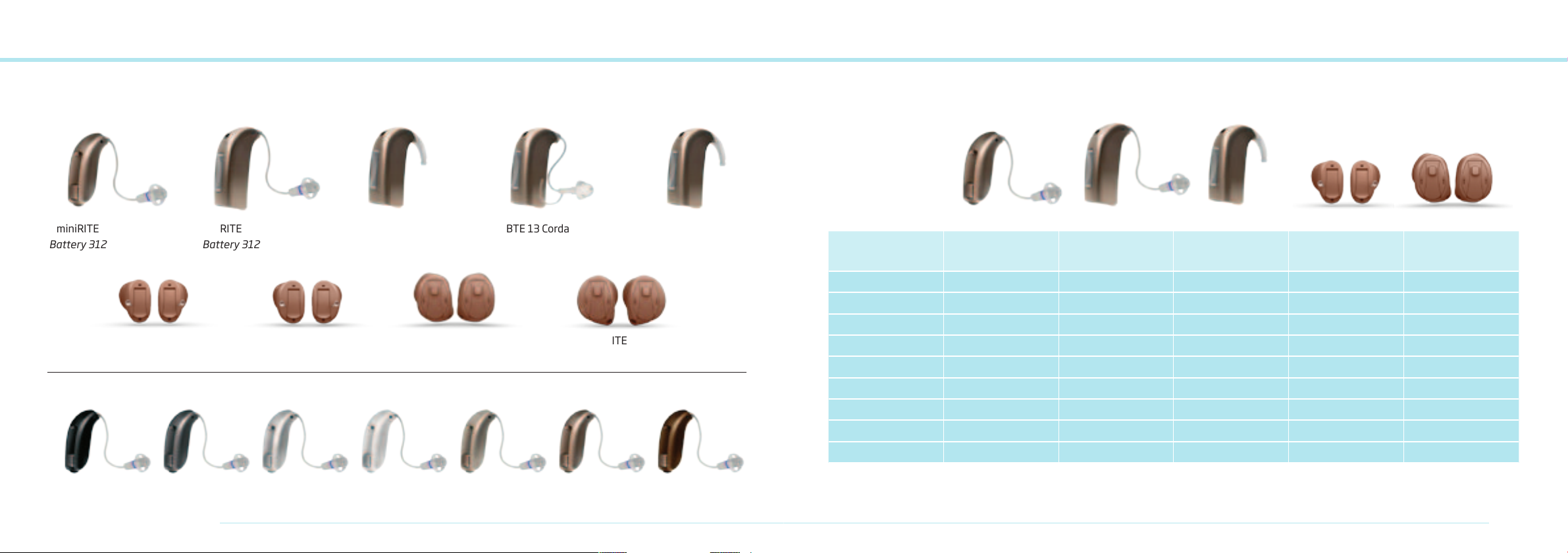
Feature-Style Quick OverviewStyle overview of Oticon Agil
miniRITE
Battery 312
CIC/MIC Power
Battery 10
Colours
Diamond Black
63
8
OTICON AGIL FITTING GUIDE
Steel Grey
92
RITE
Battery 312
CIC/MIC
Battery 10
Silver Grey
91
BTE 13
Battery 13
Silver
44
ITC
Battery 312
Chroma Beige
90
BTE 13 Corda
Battery 13
Terracotta
94
ITE
Battery 312
Chestnut Brown
BTE Power
Battery 13
93
Features miniRITE RITE BTE 13
BTE Power
Rationales
VAC / NAL / DSL
i
VAC / NAL / DSL
i
VAC / NAL / DSL
i
CIC/MIC
CIC/MIC Power
VAC / NAL / DSL
i
ITC/ITE
VAC / NAL / DSL
T-coil No Yes Yes No Optional
ConnectLine Yes Yes Yes No Yes
Auto Phone Yes Yes Yes No Optional
Push button Single Double Double None Single (optional)
Volume Control Yes* Yes Yes No Optional*
FM/DAI No Yes Yes No No
Battery size 312 312 13 10 312
Cordless fitting Yes Yes Yes No Yes
* Requires binaural fitting (2 instruments)
i NAL NL-1 and DSL v5.0a prescribed as option and for kids.
i
9
Page 6
The Complete Oticon Agil fitting Range CIC to Power Customizing the miniRITE and RITE
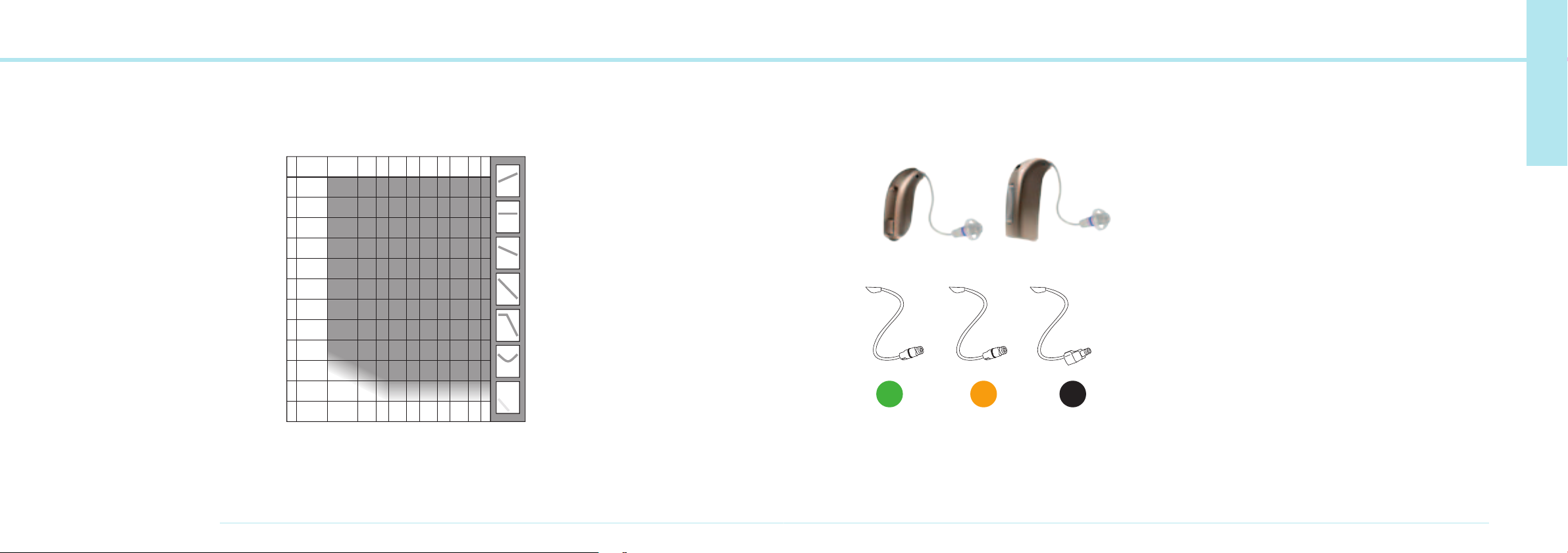
Fitting Range
10
OTICON AGIL FITTING GUIDE
-10
10
20
30
40
50
60
70
80
90
100
110
120
dB HL
0
250 500 1k 2k 4k 8k
125
Hz
S M P
To get the best performance, best cosmetics
and most comfortable fit consider the following:
• Determine whether the miniRITE or RITE is the best
style solution based on features (T-coil, FM option, etc.),
handling and cosmetics
• Select correct Receiver specifications including power
and unit length
• Select correct dome size or whether a custom Mold is
needed
• Ensure proper insertion of the Receiver in the canal when
placing the instrument on the ear
• Using the ear grip for retention, if necessary
3
11
Page 7
dB HL
dB HL
Selecting Receiver Unit Lengths
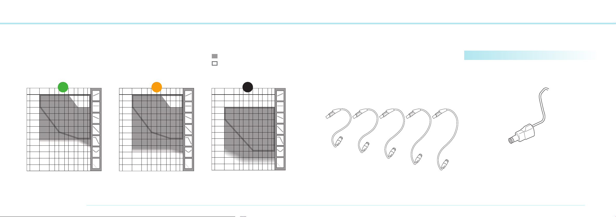
The Oticon Agil Receiver selection allows for 6 fitting
possibilities using just two instruments
Oticon Agil Receiver specifications.
-10
S M P
0
10
20
30
40
50
60
70
80
90
100
110
120
12
250 500 1k 2k 4k 8k
125
Standard: MPO (711) 119 dB
(2cc) 108 dB
Gain (711) 57 dB
46 dB
OTICON AGIL FITTING GUIDE
Hz
-10
20
30
40
50
60
70
80
90
100
110
120
0
10
250 500 1k 2k 4k 8k
125
Medium: MPO (711) 126 dB
(2cc) 116 dB
Gain (711) 61 dB
(2cc) 51 dB
Hz
Custom Mold – Power Dome
Open Dome – Plus Dome
dB HL
-10
0
10
20
30
40
50
60
70
80
90
100
110
120
250 500 1k 2k 4k 8k
125
Power: MPO (711) 132 dB
(2cc) 124 dB
Gain (711) 65 dB
(2cc) 55 dB
Hz
Five Receiver lengths are available for Standard, Medium
and Power Receivers. No. 1 is the shortest and No. 5 is the
longest. The lengths most commonly used are size 2 and 3.
Standard and Medium
1 2 3 4 5
Power:
The Power Adapter is attached to the Power Receiver
and is used when domes are preferred.
13
Page 8
Receiver markings
Measuring the ear for correct
Receiver length
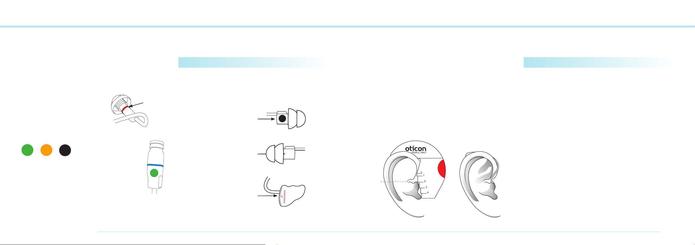
Where to find Receiver markings
The Receiver has a small blue/red band to indicate which
ear the device is programmed for.
Receiver type
The Receiver length is marked as
shown 1, 2, 3, 4, or 5.
The power specifications is shown
by a colored circle and S, M or P.
S
The power specification is selected in Genie
in the Selection Step. When the mini RITE or
Rite is selected, a pull down menu appears so
the fitter can assign the proper Receiver to
the instrument.
14
M
OTICON AGIL FITTING GUIDE
P
L (blue)/R (red)
marking
2
S
Power:
Power Receivers are marked with a black circle and a white P.
The L/R markings are on the other side. These markings are
visible when the Adapter is attached.
Power marking
Size and L/R marking
Power Custom Mold is marked
P and includes serial number
P
2R
When fitting a NON Power Receiver the correct measurement
corresponds to the top of the ear canal as shown using the
measuring tool. The measurement is the same for all domes
and non power custom earpieces.
The goal is for the Receiver to sit comfortably and be
hidden in the ear canal, and for the wire to be flush with
the skin.
Power:
Power Custom Mold
When fitting a Power Receiver with a Power Custom Mold,
(Power Molds) select the next size up as the Receiver fits more
centered in the ear canal.
For example if a # 2 Receiver is measured order a # 3.
For Power Domes measure the same way as for Standard
Receivers.
15
Page 9
Attaching the Receiver Unit
Replacing the Receiver Unit Attaching the Ear Grip
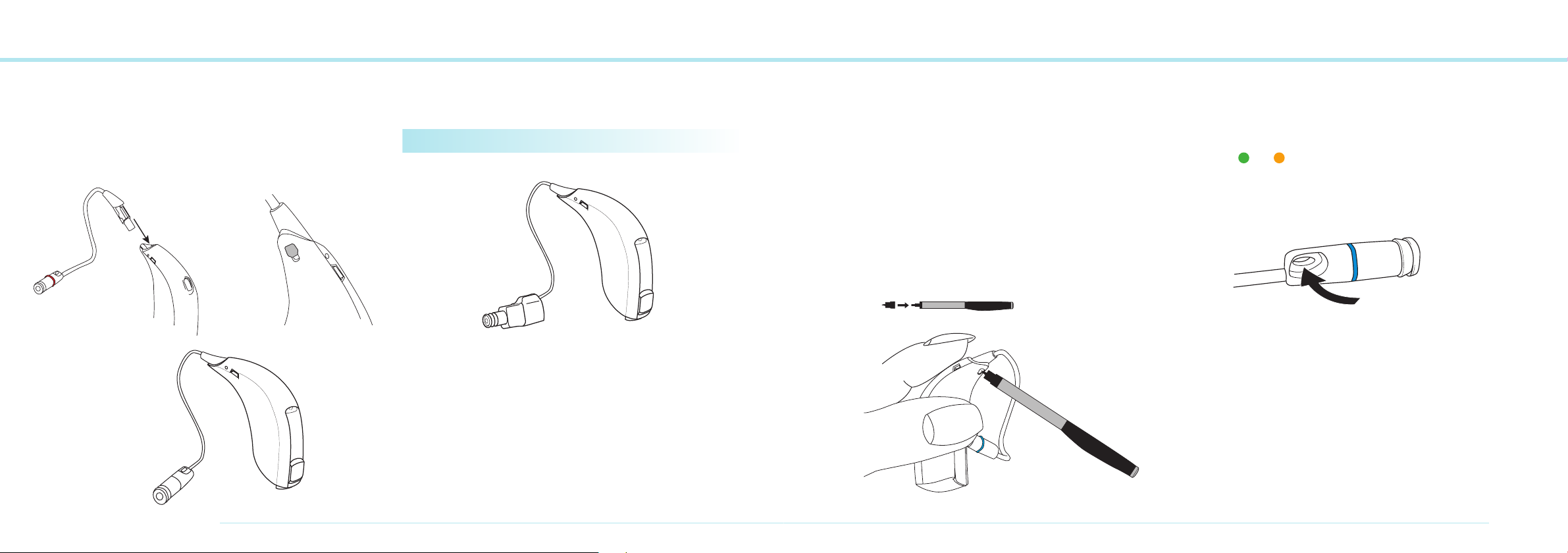
The Receiver attachment is the same for all three Receivers.
Insert the Receiver into the shell until it snaps into place.
1
2
3
16
OTICON AGIL FITTING GUIDE
Power:
Receiver with Adapter
The best way to replace the Receiver is by using the Multi tool
with the dedicated extension point. The extension point is
placed on the screwdriver tip.
Press the Receiver locking lever through the hole to release
the Receiver unit and gently pull the Receiver unit out.
The Ear Grip can be used for better Receiver retention when
using the “
for either the right or left ear. Insert the Ear Grip in the slot in
the Receiver.
S
” or “M” Receiver. The Ear Grip is designed to work
17
Page 10
Removing the Ear Grip Inserting and placing the device on the ear
18
OTICON AGIL FITTING GUIDE
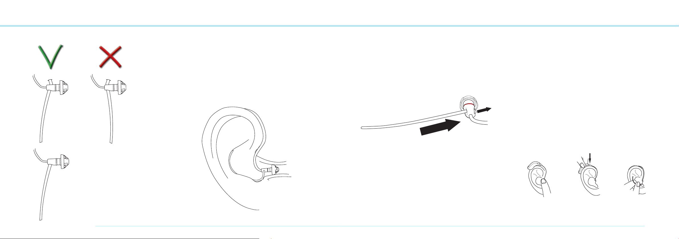
Pull the ear grip until its top is positioned
in the slot. During insertion, the top should
point away from the dome as illustrated.
If the ear grip is too long in the concha it may be trimmed.
Use caution not to leave a pointy end as this may irritate
the ear.
Use a finger nail to dislodge the ear grip and push from
the other side.
1. Insert the earpiece into the ear canal.
2. Place the hearing device behind the ear. The Receiver unit
with the correct earpiece should be placed far enough into
the canal so that the wire lies flush with the client’s head.
When looking at the client face to face you should not see
the Receiver wire sticking out.
3. If necessary add the ear grip for extra retention.
1 2 3
19
Page 11
Shaping the Receiver Unit
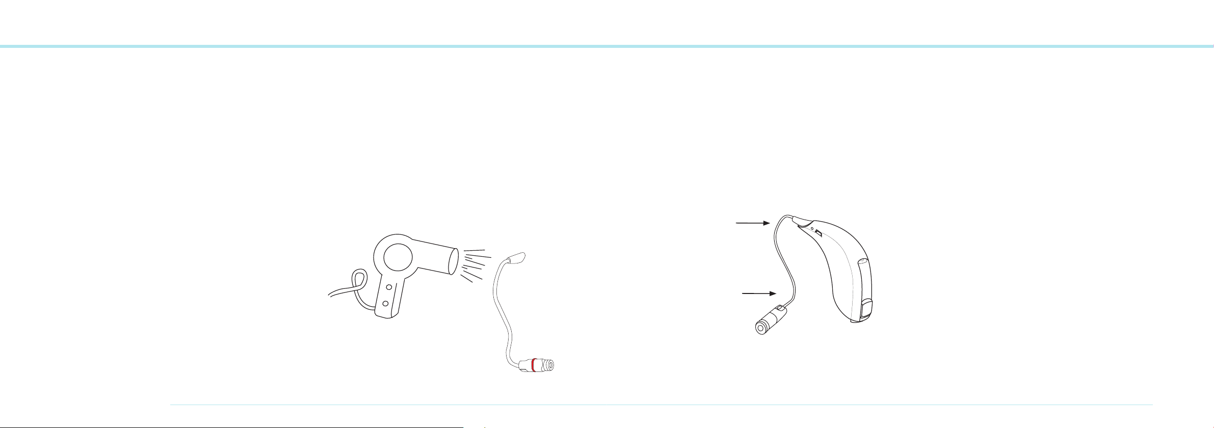
To better customize how the hearing device fits on the ear
it may be necessary to manipulate the Receiver. This is
especially true if the Receiver wire is too short and the
client reports that the earpiece tends to slip out or it can’t be
inserted deep enough in the ear canal.
One check for this situation is to try another dome size.
Sometimes a smaller dome size will allow the Receiver unit to
move further in the canal.
If the wire is still not flush, you might want to change the curve
of the Receiver wire to either straighten it a little or to change
the insertion depth. This is not difficult, but the following
steps are important to avoid damaging the Receiver unit:
20
OTICON AGIL FITTING GUIDE
• Use a hair dryer or spectacle instrument at low heat setting.
• Heat for a short time – a matter of seconds.
• Bend into desired shape and hold shape until wire
is cooled off.
• Do not use excessive heat and do not exceed 130°C.
Lengthening the Receiver
• To add length to the Receiver straighten the S portion
of the Receiver wire as marked.
S-curve
Bend into the canal
Bend into the Canal
• Adjust this bend to stop the wire from bowing out from
the side of the client’s ear, or to increase the depth of
Receiver insertion.
21
Page 12
Earpieces
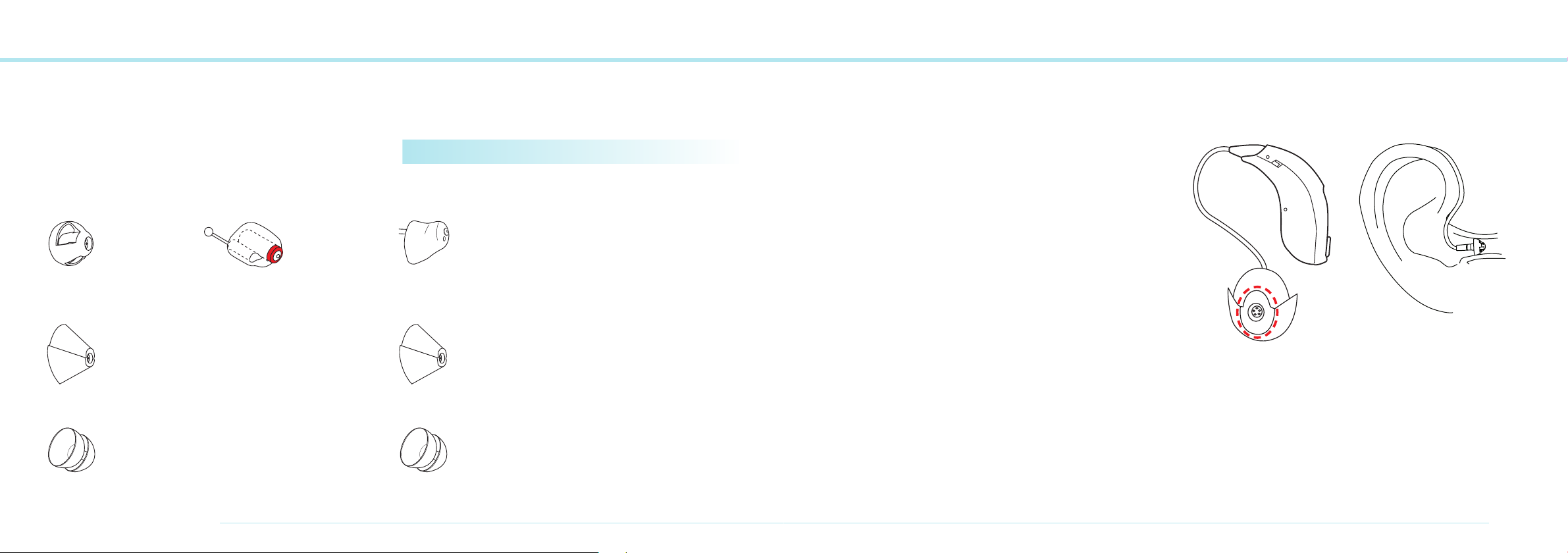
Dome and Custom Mold selection for Standard,
Medium and Power Receiver
Standard or Medium
Open Dome
6 mm
8 mm
10 mm
Plus Dome
One Size
Power Dome
8 mm
10 mm
12 mm
RITE Molds
Molds
(soft silicone
or hard acrylic)
Power:
Power Mold
For power custom
fittings only
Plus Dome
One Size
Power Dome
8 mm
10 mm
12 mm
Selecting Dome
The Open Dome is available in three different sizes:
6 mm, 8 mm and 10 mm. The most commonly used is the
medium sized 8 mm Dome.
The Open Dome is suitable for hearing losses up to 70 dB in
the high frequencies and is the best option for most users.
The Plus Dome allows more mid-frequency gain and extends
the fitting range to 80 dB HL in the high frequencies. It is suitable if the user wants more loudness or more mid-frequency
gain. Genie will automatically prescribe Open or Plus Dome.
The Plus Dome is available in one size.
You also have the possibility of selecting Power Domes
for close instant fittings up to 80 dB flat hearing losses.
The Power Dome is available in three different sizes:
8 mm, 10 mm and 12 mm.
The oval tip of the Plus Dome
should always be placed on the
Receiver unit as illustrated.
The Dome should sit comfortably
in the ear canal and support and
hold the Receiver.
22
OTICON AGIL FITTING GUIDE
23
Page 13
RITE Micro Molds for the Standard
or Medium Receiver
RITE Molds for Standard and
Medium Receivers
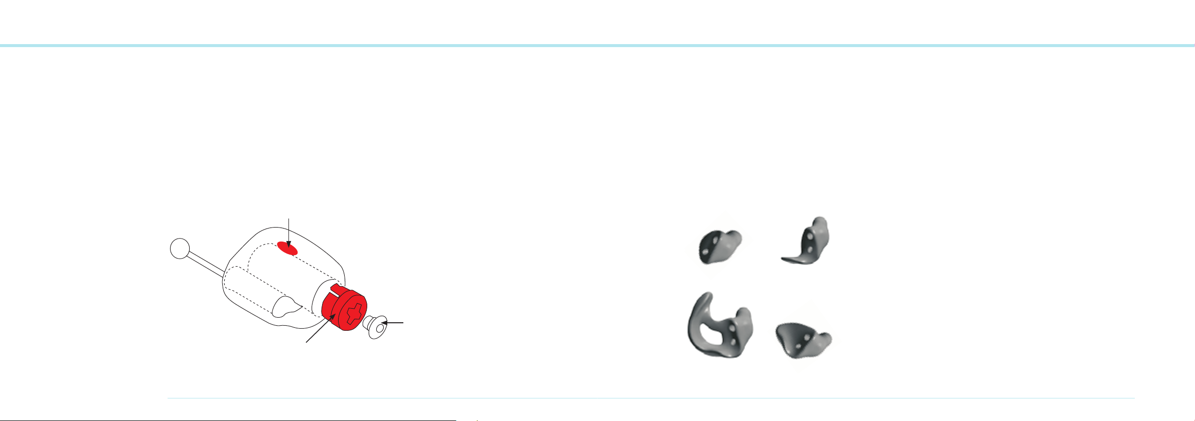
The Micro Mold is an acrylic custom solution that can be used
instead of a dome for a RITE fitting.
NOTE: If there is a receiver change from S to M a new Micro/
Custom Rite mold will be needed as the M Receiver is slightly
larger than the S.
Up/Down Indicator
Adapter
24
OTICON AGIL FITTING GUIDE
Micro Molds are produced from a traditional, deep impression.
The Adapter clearly indicates R (red) /L (blue) color marking.
All custom molds should never be cleaned with a solvent such
as alcohol as it will loosen the wax adaptor over time.
WaxStop
Custom RITE Molds are produced from a traditional, deep
impression. Custom RITE Molds can be ordered as canal or
skeleton style with various modifications. See Custom RITE
Solution Guide for complete overview.
NOTE: Canal and Micro Molds are also available in SOFT
sillicone. These molds slide over the receiver tip and do not
require any tools to install.
Canal
Skeleton lock
Canal lock
Half shell
25
Page 14

Short Vents Long Vents
Attaching the RITE Mold
Micro Molds use tube-shaped vents, as in traditional ear Molds,
but the length is shorter than standard vents. Therefore, the
Micro Mold vent effect is much larger than its actual diameter.
Genie prescribes the vent size, when Micro Mold is selected.
Check the Micro Mold vent size under Acoustics in Fitting step.
For further information about selecting vent sizes and
effective vent sizes please refer to the Genie helpfiles under
Acoustics.
Micro Mold Actual vent size (mm)
X-Large >2.4
Large 2.4
Medium 1.4
Small 0.8
No Vent 0
26
OTICON AGIL FITTING GUIDE
Custom RITE Molds use tube-shaped vents just like Micro
Molds. However, the vent is a little longer. Still, the canal’s
vent effect is larger than its actual diameter. Genie prescribes
the vent size (from X Large to No Vent) when Micro Mold is
selected. To reflect the actual diameter select the vent size for
long vents, e.g. Large (long).
RITE Molds Actual vent size (mm)
X-Large >2.4
Large 2.4
Medium 1.4
Small 0.8
No Vent 0
When fitting Oticon Agil RITE hearing devices with RITE Molds
follow the instructions below:
Find the correct Receiver unit length and attach it to the
instrument (see Selecting Receiver Unit Length).
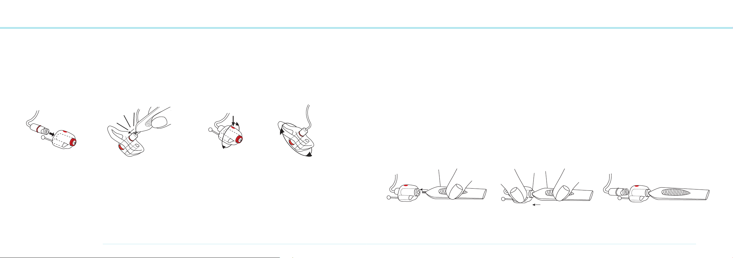
1. Carefully insert the Receiver into the RITE Molds and
push until you hear/feel a click.
2. When inserting the Receiver into a modified RITE Molds
with a longer canal, use the Mold tool to snap the Receiver
more deeply into the Mold, as pictured.
3. The Mold can rotate axially to ensure maximum comfort.
Before placing the Mold in the ear, turn the Mold until
the up indicator points upwards.
27
Page 15
Taking off the RITE Mold
RITE Mold Receiver Insertion Canal Receiver Insertion
1 2 3a
Note: Make sure that the Receiver is not angled when inserted into the Mold. An odd angle will prevent the Receiver from
engaging the Adapter. The click sound indicates that the Receiver is placed correctly, and it should be done with only a little
force. Don’t force the two units together!
28
OTICON AGIL FITTING GUIDE
3b
The Mold can’t be detached from the Receiver
without the Micro Mold tool
When detaching the Micro Mold follow the instructions
to the right:
1 2 3
1. Remove the WaxStop.
2. Place the Micro Mold in the tool as illustrated making sure
that the cross in the Adapter is matching the tap of the tool.
3. Press the tool into the Mold to release the Receiver unit.
4. Now the Micro Mold can be removed from the Receiver unit.
5. Never remove the existing wax top from the Receiver.
It is part of the locking mechanism.
29
Page 16
RITE Power Fittings
RITE Power with Power Mold
Measuring Considerations for Power Fits
RITE Power uses a high performance Receiver which requires
ample room in the ear canal. To determine if your client’s ear
canal can accommodate this Receiver and an additional 2 mm
vent, please use the measurement gauge supplied.
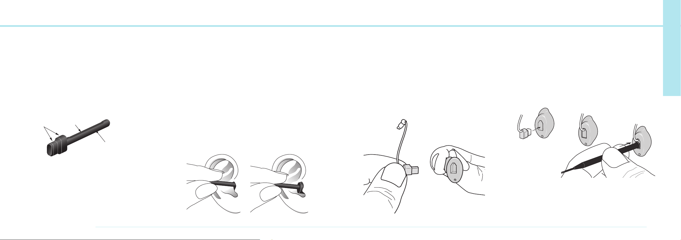
Using the measurement gauge
Size indicator
1. Hold the handle of the measurement gauge so that
the plane side of the handle is up.
2. Insert the gauge into the ear canal (with the plane side up)
until the size indicator is fully surrounded by the ear canal.
If the size indicator fits easily within the ear canal, the client
is an excellent candidate for RITE Power.
Plane side
Handle
3. If the size indicator does not fit in the ear canal but is hidden
behind the tragus when viewing from a 45 degree angle,
the Power Mold can be fit. If the size indicator is visible
when viewed from a 45 degree angle, the client is not a
candidate for a Power Mold.
Note: The gauge must be cleaned and sterilized before
re-use. First clean any visible cerumen from the gauge with
a dry or moist tissue. Next soak the gauge in a cold sterilant
for at least 6 hours.
1-2 3
Attaching the Power Mold
Use a Power Receiver without an Adapter housing.
If the Receiver has an Adapter, see page 34 for instructions
on how to remove this. Hold the Receiver unit in one hand
and the Power Mold in the other hand, positioned as
illustrated.
Insert the Receiver unit into the Mold until it is fully covered
and recessed to approx. 1 mm. Use the back of the removal
tool if needed.
4
30
OTICON AGIL FITTING GUIDE
31
Page 17
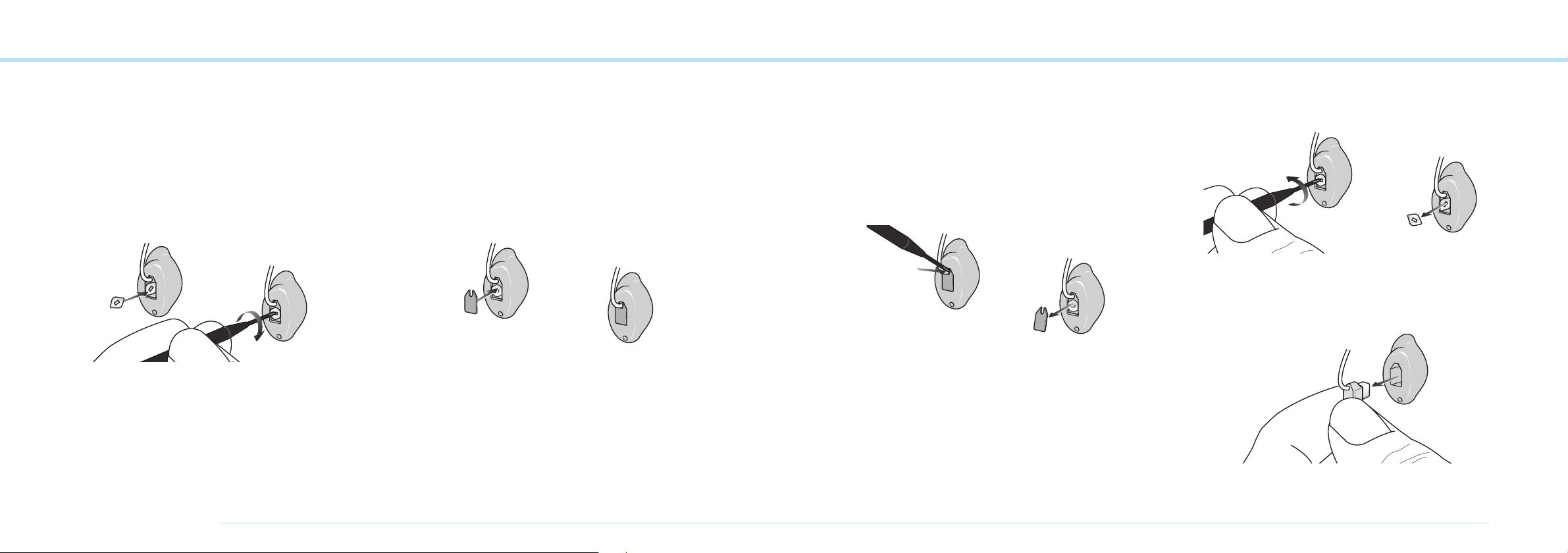
Removing the Power Mold
Place the locking plate on the Receiver housing and use the
special screwdriver provided in the kit to turn the locking plate
approx. 45 degrees clockwise until it locks into the grooves of
the shell.
32
OTICON AGIL FITTING GUIDE
Next snap the Receiver cover into the faceplate, covering the
Receiver housing and surrounding the base of the tubing for
reduced visibility.
To remove the Receiver unit, first remove the cover by very
gently sliding the screwdriver between the tube and the cover
and applying a slight upward pressure.
Grasp the Receiver unit as illustrated and pull straight out from
the Power Mold.
Using the screwdriver, turn the locking plate counterclockwise
by approx. 45 degrees. You will feel a slight release and then
remove the plate.
33
Page 18
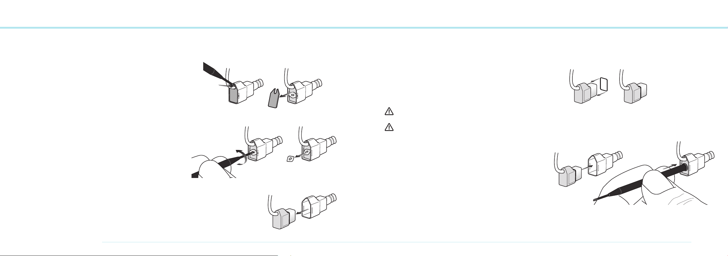
Power Adapters
Changing from Mold to Dome
When replacing the Receiver unit in a Power Mold using
a Receiver unit from the RITE Power shop kit:
1. First remove the cover by very gently sliding the screw-
driver between the tube and the cover and applying a slight
upward pressure.
2. Using the screwdriver, turn the locking plate counterclock-
wise by approx. 45 degrees. You will feel a slight release and
then remove the plate.
3. Pull the Receiver unit out from the adaptor.
4. Attach new Receiver gasket as shown on page 35.
5. Follow instructions on page 31 to attach a new Receiver
to Mold.
34
OTICON AGIL FITTING GUIDE
1
2
1. Remove Receiver unit from Power Mold as shown
on page 33.
2. Attach dome housing to the Receiver unit as shown.
First, insert the gasget on to the Receiver unit
as shown.
A new Receiver gasket seal must be used each time
the Receiver unit is attached to the shell.
Slide the Receiver gasket being carful not to roll it.
3. Mount the transparent dome housing onto Receiver unit.
4. Fix the Receiver unit by a locking plate.
5. Place the transparent cover on the dome housing.
2
3
3
35
Page 19
BTE 13 with Corda
0-0.9 0-0.9
589-25-140-00 (5x)
1-0.9
589-25-131-00 (5x)
1-0.9
589-25-141-00 (5x)
2-0.9
589-25-132-00 (5x)
2-0.9
589-25-142-00 (5x)
3-0.9
589-25-133-00 (5x)
3-0.9
589-25-143-00 (5x)
911 49 500 00/ 02.08
589-25-130-00 (5x)
589-25-150-00 (10x)
589-25-120-00 (10x)
890-22-270-00 (1x)
502-15-191-00 (3x)
890-21260-00
(20x)
890-21250-00
(1x)
570-07-430-00 (10x)
S
570-07-431-00 (10x)
M
570-07-432-00 (10x)
L
589-25-100-00 (10x)
Plus
2
4
5
36
OTICON AGIL FITTING GUIDE
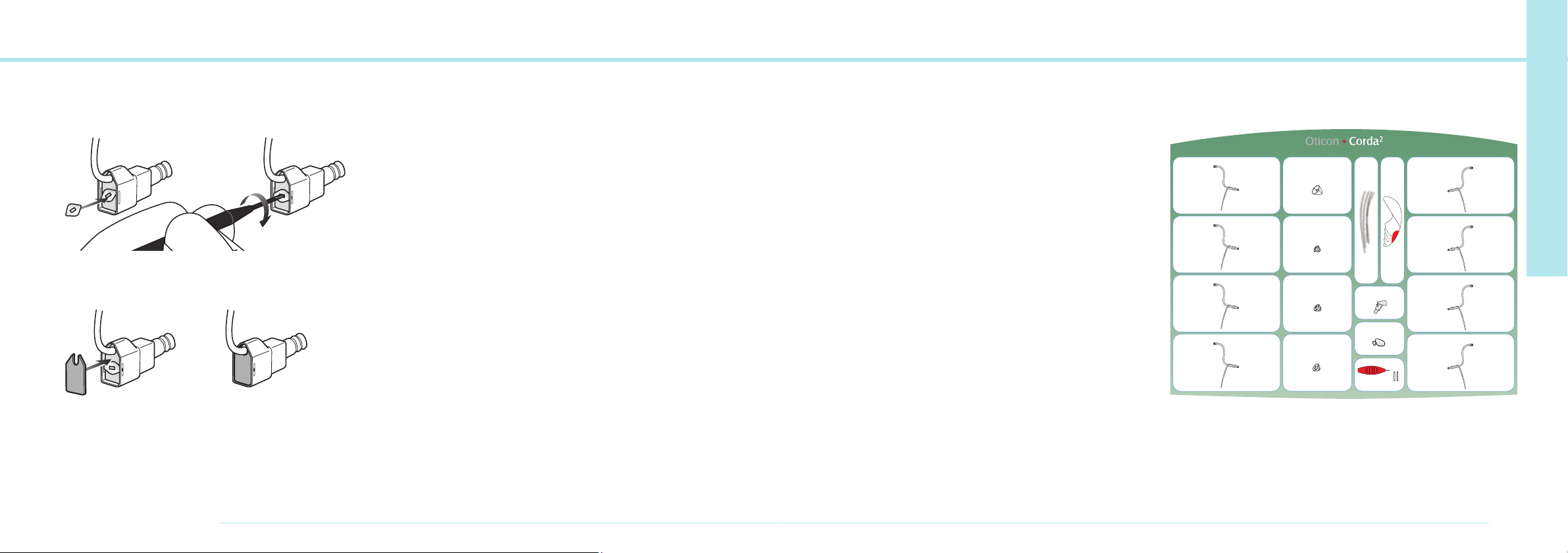
BTE 13 can be adapted for use with Corda2 thin tube fitting.
2
The Corda
kit contains all elements for success with
thin tube fittings including:
• Left and right tubes in four lengths
• Three sizes of Corda Open Domes
• Corda Plus Domes
5
• Measurement tool and cleaners
• Corda
• Adapter for RISE instruments
• Adapter for older instruments
2
Quick guide
• Service tool and extra pins for Adapter/hook attachment
Please refer to the Corda
2
Quick guide for complete
information.
37
Page 20

Custom Mold
Fitting Corda2 with Molds in Genie
A Micro Mold is an option for Corda2 solutions on BTE 13.
Additional Rite Molds are also available in e.g. canal lock and
skeleton canal for improved retention, when necessary.
Micro Molds in all shapes or canal Molds are produced from
a traditional, deep impression.
Micro Mold
Canal Lock
Skeleton Canal
Half Shell
1. Select Corda2 instead of earmold.
2. Go to the fitting step and verify the vent size of the molds.
Select “Open dome” for an open mold with 4 mm vent or
“Plus dome” for a 3 mm vent.
Note: Fine tuning might be necessary when working
with Molds.
38
OTICON AGIL FITTING GUIDE
39
Page 21
Connecting Oticon Agil to Genie
Oticon Agil is programmed using the Genie fitting
software compatible with NOAH 3.0 and Oticon
programming cable #3 (right and left)
The table shows how to connect
the different styles when fitting with cables
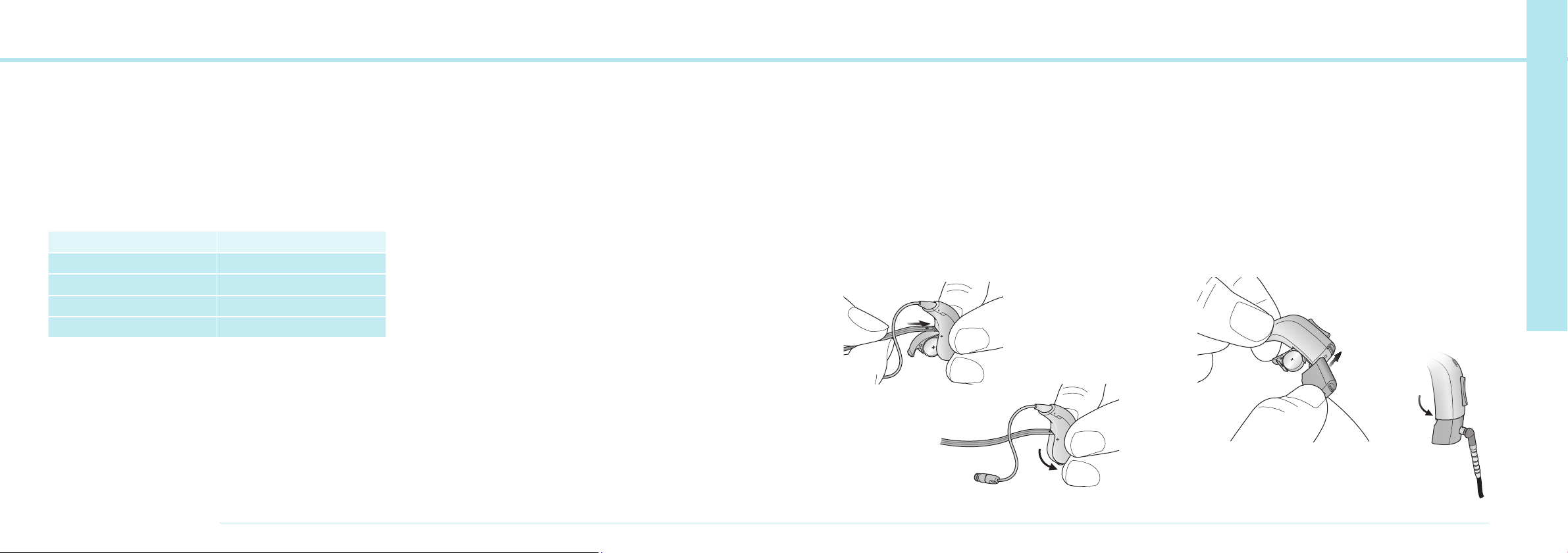
Instrument Style Programming Interface
miniRITE Flex Connect
BTE/RITE Programming Shoe
ITC/ITE Programming Adapter
CIC/MIC Flex Connect
40
OTICON AGIL FITTING GUIDE
Connecting Flex Connect to miniRITE
1. Open the battery door on the instrument and slide
the Flex Connect into the instrument as shown
(pointing the black dot on the cable upwards).
Insert a fresh battery.
2. Close the battery door and attach the HI-PRO or
NOAHlink cable.
1
2
Connecting the Programming Shoe
to BTE and RITE
1. Open the battery door on the instrument and slide
the programming shoe into the guide as shown.
Insert a fresh battery.
2. Close the battery door and attach the HI-PRO or
NOAH link cable.
1
6
2
41
Page 22
Custom Products
nEARcom
Connecting the Programming Adapter
to ITE and ITC
1. Open the battery door and slide the programming Adapter
into the battery door as shown. Make sure the red arrow
marking on the Adapter is next to the + marking on the
guide and that the flip is inserted correctly.
2. Close the battery door and attach the HI-PRO or
NOAHlink cable.
42
OTICON AGIL FITTING GUIDE
Connecting CIC/MIC
1. Open the battery door and insert the Flex Connect
into the open space next to the battery door as shown
(pointing the black dot on the cable upwards).
Insert a fresh battery.
2. Close the battery door and attach the HI-PRO or
NOAHlink cable.
1
2
For greater flexibility and comfort use nEARcom without
cables to fit Oticon Agil instruments.
(CIC/MIC instruments cannot be programmed by nEARcom).
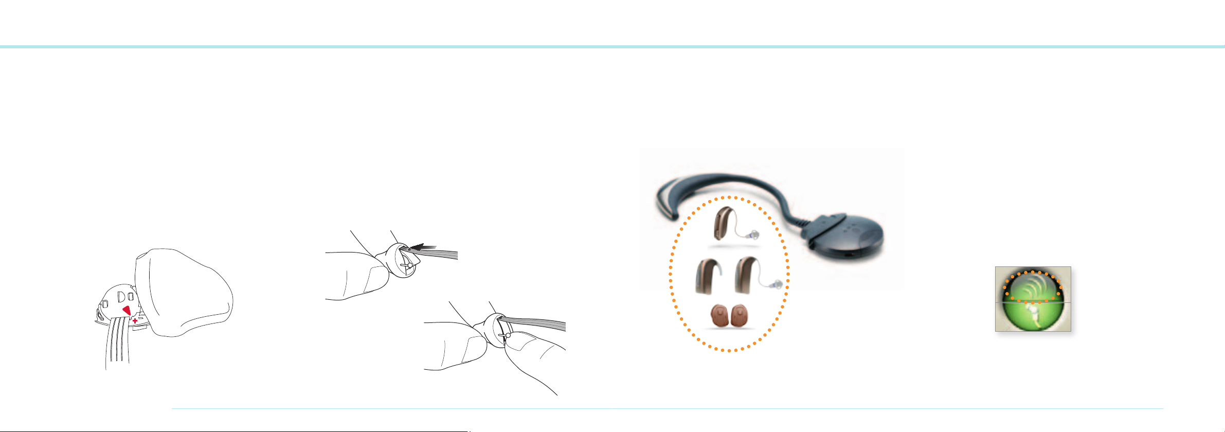
Detect the instruments
1. Switch on the instruments using fresh batteries.
2. Lay nEARcom on the table and place the instruments
in the middle of the neck loop.
3. Click Detect for cordless programming.
Cordless programming
Wired programming
43
Page 23
Programming Oticon Agil
Structure in Genie
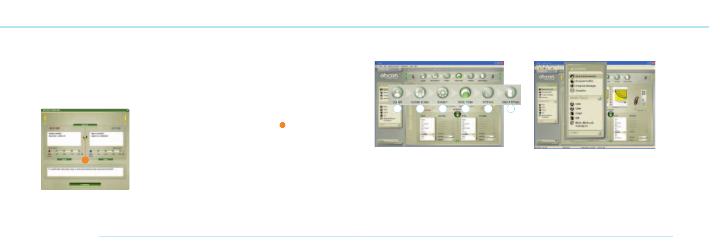
Instruments which have never been programmed must
be assigned to the correct side – left and right – in Genie.
Use a BEEP test as follows:
1
44
OTICON AGIL FITTING GUIDE
To identify the instrument place it in the middle of the
neck loop and click BEEP. The instrument will beep for
6 seconds.
While the instrument is beeping, remove it from
nEARcom and listen to it.
If the instrument does not beep, return it to the middle of
the neck loop, click the Change side icon
same BEEP. Listen to the instrument again.
Click Continue and proceed with the programming.
1
and click the
1
2 3 4 5 6
The Organizer – Horizontal Navigation
Main programming steps
1. Client: Appears only when running Genie outside NOAH.
2. Counseling: Appears only if Gateway has been installed.
3. Family: Selection of all hearing instrument families.
4. Selection: Select instrument styles and features.
(incl. Streamer).
5. Fitting: Verifying and fine tuning of settings.
6. End Fitting: Verify and set user operated buttons
and link Streamer.
Task Pane – Vertical Navigation
In each organizer step there is a Task Pane that gives access to
tools and links related to where you are in the fitting process.
45
Page 24
Family Step
Selection Step
46
OTICON AGIL FITTING GUIDE
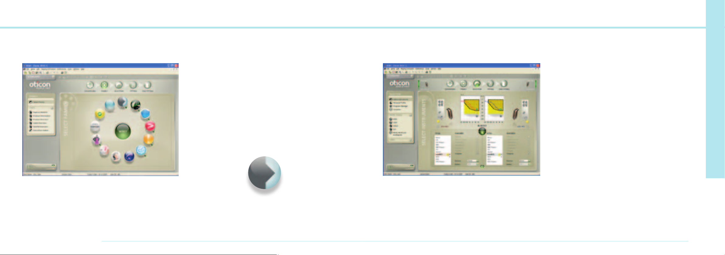
Click ‘Detect’ to detect connected instruments. Genie will
display what has been detected. Click Continue to go to the
selection screen.
Note: You can simulate a fitting by selecting ‘Oticon Agil’ from
the Family circle. Select Oticon Agil or Oticon Agil Pro from the
second level screen that opens.
Oticon Agil comes in all styles from CIC to BTE Power including
RITE (Receiver In The Ear).
Oticon Agil has a number of options. Not all options are
available in all styles. If a style is selected, only the options
available in that style will be visible. If a style has not been
selected, select the relevant features you want and Genie will
display available instruments that match your criteria.
Auto Phone will ensure that the instrument automatically
switches to a dedicated phone program (either telecoil or
microphone) when a phone is held to the ear.
If you are fitting ConnectLine or just add Streamer as a remote
control to the Oticon Agil instruments, select Streamer in the
feature list.
If you are working with Corda
and select Corda
In the Personal Profile you can provide extra information
and thereby get a more individualized fitting for your client.
2
under Earpiece.
2
, select or detect the BTE 13
47
7
Page 25
Fitting Step
Controls
The connection bar indicates whether the instrument is
either: Not Connected (Grey); Connected with data changed in
Genie but not saved in the instrument (Yellow); or, Connected
with settings programmed and stored in the instrument
(Green).
48
OTICON AGIL FITTING GUIDE
The Adaptation Manager provides easy access to a gradual
acclimatization process in three steps. Changing steps effect
gain, compression and the frequency response.
Instruments can be fine tuned in each of 10 independent
frequency channels. By default, the 10 channels are gathered
in three frequency regions: LF, MF and HF.
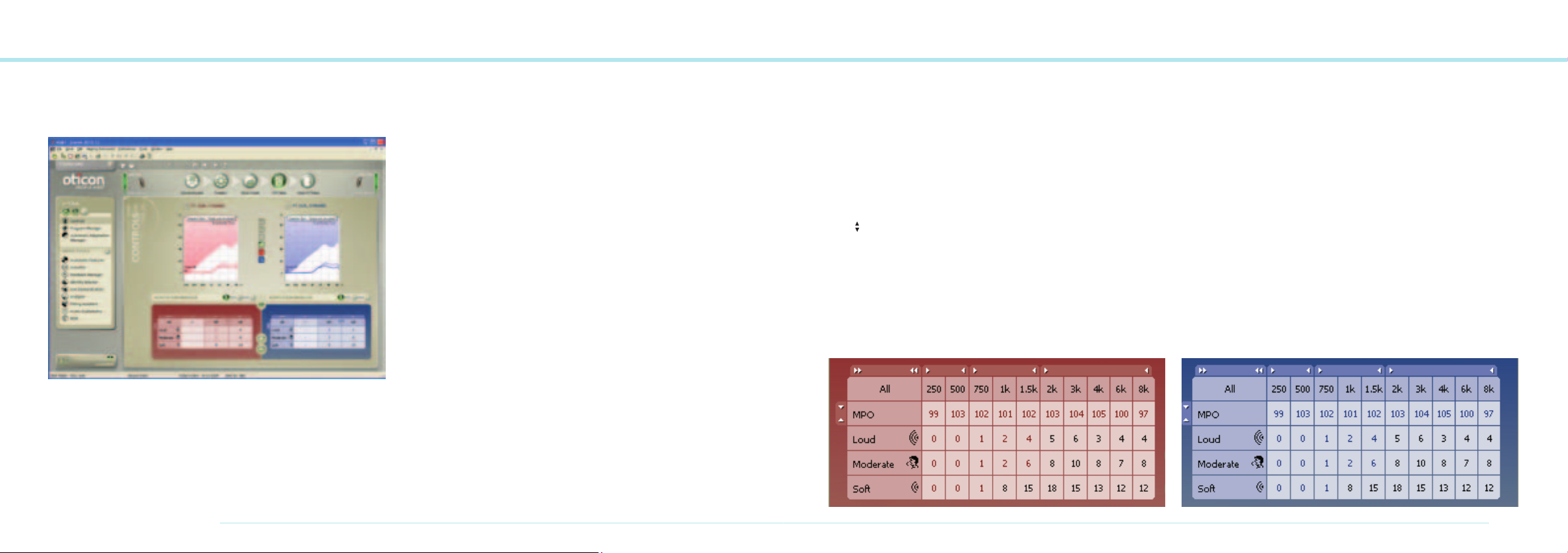
Soft (45 dB SPL), Moderate (65 dB SPL) and Loud (80 dB SPL)
input levels can be adjusted. Select all three LF, MF or HF
controls by clicking the LF, MF or HF button in the table.
By selecting “All”, all gain controls will be selected, the colors
of the control values are blue (left) and red (right) when the
device is at prescribed settings.
If the control value is no longer at prescribed settings,
the value turns black.
Adjusting the fitting controls
By clicking the <> each or all of the three regions (LF, MF and
HF) can be expanded to display all the underlying frequency
channels.
Click
to display the MPO controls for each region or channel.
Adjust the gain controls in 1 dB steps in the selected fields.
MPO is displayed in dBHL while gain is displayed in dB (IG).
RITE/Corda2 only:
For RITE instruments and BTE 13 instruments with Corda2 with
domes no low-frequency gain is provided in the initial setting
due to the dominating natural sound.
Therefore the LF region is disabled (greyed out) in the fitting.
If you want to make adjustments in the LF region, expand the
region and you will get access to the underlying frequency
channels.
49
Page 26
Program Manager
Automatic Adaptation Manager
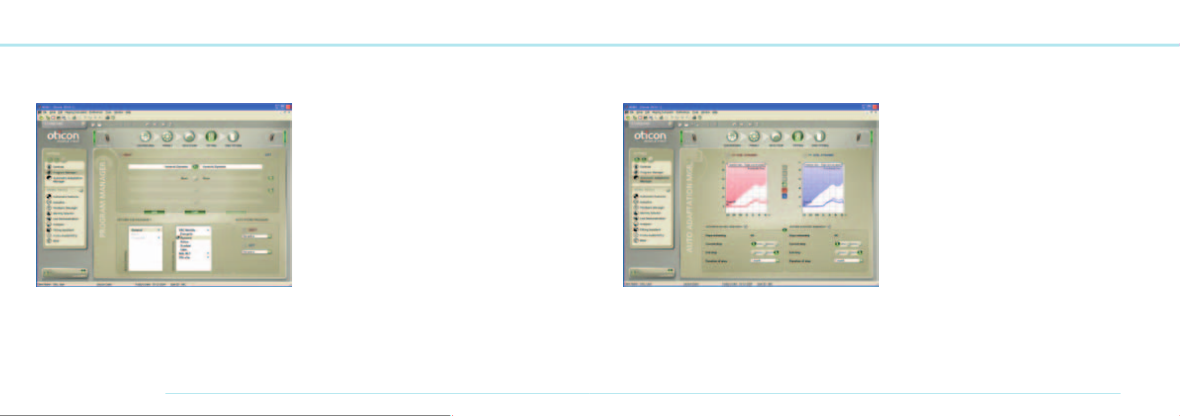
In the Program Manager you can activate, configure, delete,
and change the order of the programs. For general programs
you can choose between the VAC, NAL NL1 and DSL v5.0 fitting rationales. Two phone programs exist, Microphone (M)
or telecoil (T). You choose whether you want to activate the
phone program on the left or right ear. By default a copy of
P1 reduced will be placed in the other instrument.
50
OTICON AGIL FITTING GUIDE
If you have an Auto Phone in the instrument, you can activate
the automatic functionality in the lower right corner.
You do not have to add a Phone program in P2 – P4. You can
choose whether the program should be a Microphone or a
Telecoil program (when Telecoil is available). This program is
configured either here or in the End Fitting Step.
If you are fitting ConnectLine to your Oticon Agil instruments,
adjustments to ConnectLine programs are done in the
End Fitting step.
RITE and BTE instruments are compatible with DAI and FM
shoes. When the shoe is attached to the instrument, you will
automatically have access to two extra programs:
• DAI/ FM + Microphone (default) and
• DAI/FM only.
The two programs are based on the settings in P1.
Any adjustments are handled in the End Fitting step.
The three step Adaptation Manager helps clients gradually
adjust to the full response of hearing instruments.
Set the Adaptation Manager
1. New users
2. Semi-experienced and experienced users
3. Experienced users.
Verify the prescribed setting, for example by using the various
built-in sounds and sound environments in Genie.
Automatic Adaptation Manager
Specifying the transition time between steps allows for an
automatic and smooth acclimatization period.
4. Check to activate the Automatic Adaptation Manager.
5. Set the initial and final step for the adaptation process.
6. Specify the adaptation time.
51
Page 27
Automatic Features
Other Tools
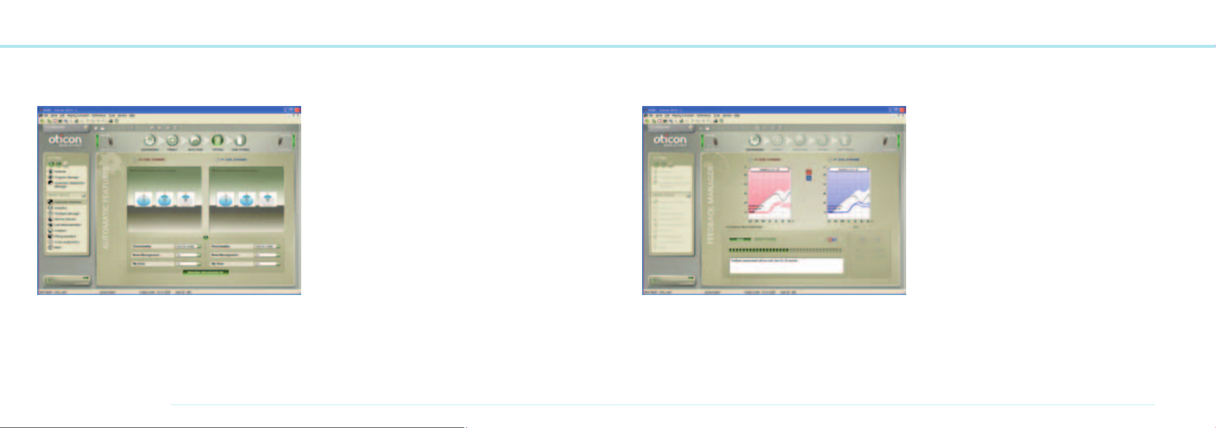
In the Automatics section you can enable or disable the Automatics in Oticon Agil instruments.
Multiband Adaptive Directionality is designed to provide
benefit from Directionality in situations where the Speechto-Noies can be improved. Through Binaural Broadband
52
OTICON AGIL FITTING GUIDE
the Multiband Adaptive Directionality in Oticon Agil Pro is
synchronised between right and left hearing instruments.
TriState Noise Management uses VoiceFinder to detect if
speech in present or not. Noise Reduction will be applied to
provide comfort in noisy situations without compromising
important speech cues. Binaural Broadband will ensure that
the information in Oticon Agil Pro is synchronized between
right and left hearing instruments to ensure best possible
speech understanding in any environment.
My Voice in Oticon Agil Pro is able to recognize the client’s own
voice. This information is used by TriState Noise Management
to ensure that the cllient’s own voice does not affect the
amount of Noise Reduction.
Binaural Broadband is available for Oticon Agil Pro only
and controls the synchronization between the two hearing
instruments. Binaural Broadband is default on. If disabled
this will also disable the binaural coordination of push button
operations.
Acoustics:
Use the Acoustics tool to change vent size or dome type.
Feedback Manager:
This is a fast and effective way to set the instrument’s feedback limits to ensure that no static feedback is present.
If feedback occurs, run the FBM from P1. The feedback limits
will be applied to all programs in the hearing instrument.
Note: It is not possible to adjust the controls above the new
feedback limit. Gain limits applied to the control setting
depend on whether the DFC
This means that gain can be increased more when the DFC
is enabled.
All Oticon Agil instruments have Dynamic Feedback Cancellation2 that contributes to the instruments’ superb sound
quality.
2
system is active or not.
2
53
Page 28
Live Demonstration
54
OTICON AGIL FITTING GUIDE
Identity Selector:
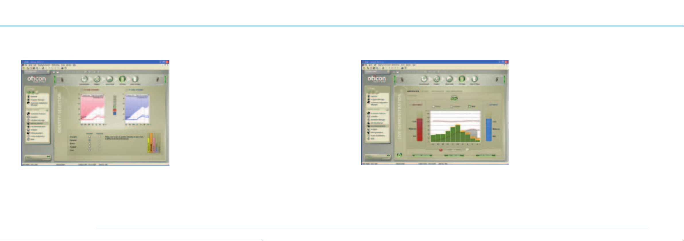
In the Identity Selector you can change between the different
identities. If any fine tuning has been done in the current
Genie session, it is also possible to change between fine tuned
and prescribed identities.
With the VAC rationale there are 5 identities to choose from
and with the NAL NL1 rationale there are 3.
Note: Identities and the Identity Selector are not available
for the DSL v5.0a rationale.
Live Demonstration is designed to show in real time how
Oticon Agil evaluates the listening environments in several
dimensions. Live Demonstration consists of three elements:
Amplification, Directionality and Noise Management. Live
begins automatically once an instrument is connected.
You can pause Live by clicking the On/Off button on the left.
To demonstrate the response for one ear at a time, select L
or R to switch between ears. Play the relevant sound environments suggested in the tabs to support your demonstration.
55
Page 29
Life Learning
The Amplification tab shows the actual aided response
(output) vs. the unaided input, as well as both (input and gain).
Use the ear icons to switch between ears when demonstrating
one ear at a time. Use the mute button to temporarily let the
client compare the sound of the instrument with an unaided
response.
The Directionality tab displays the current directionality mode
of both instruments: Surround, Split or Full. The icons on each
side indicate what directionality mode each instrument is in.
56
OTICON AGIL FITTING GUIDE
Noise Management shows how much noise is reduced by
the Noise Management system in each fitting channel and
how speech is preserved. The right and left panels show the
sound environment (Quiet, Speech, Speech in Noise, Noise or
Wind) as it is detected by each instrument.
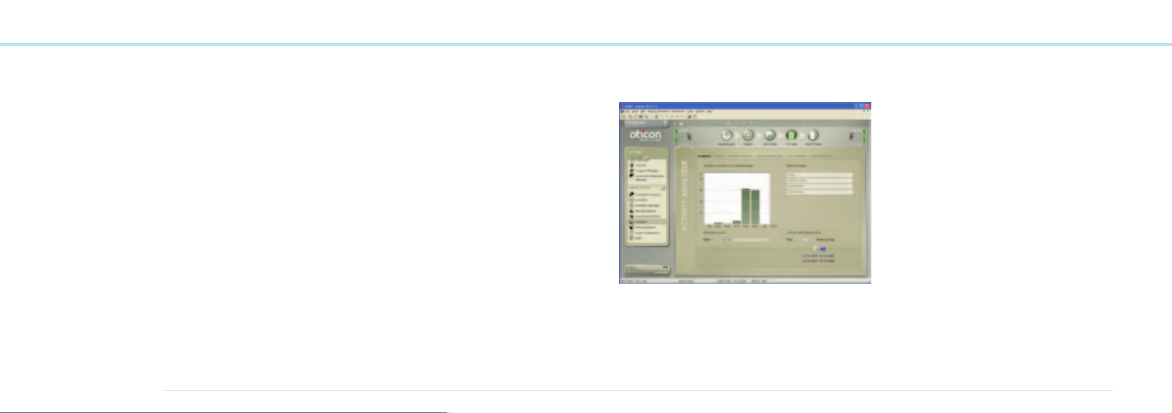
Oticon Agils Life Learning displays instrument usage and
environmental data. After the instruments are programmed
in Genie and switched on, they start to collect data and learn.
At a follow-up visit you can open Life Learning and see the
acquired statistics.
Oticon Agil does not log information while connected to Genie.
Summary provides an overview of the data and learning
collected in the instrument.
Usage displays total instrument and program usage.
Volume control is active for instruments with a volume control
and analyses the use of it.
Signal processing the Envirogram summarizes the overall
sound levels for all general programs.
57
Page 30
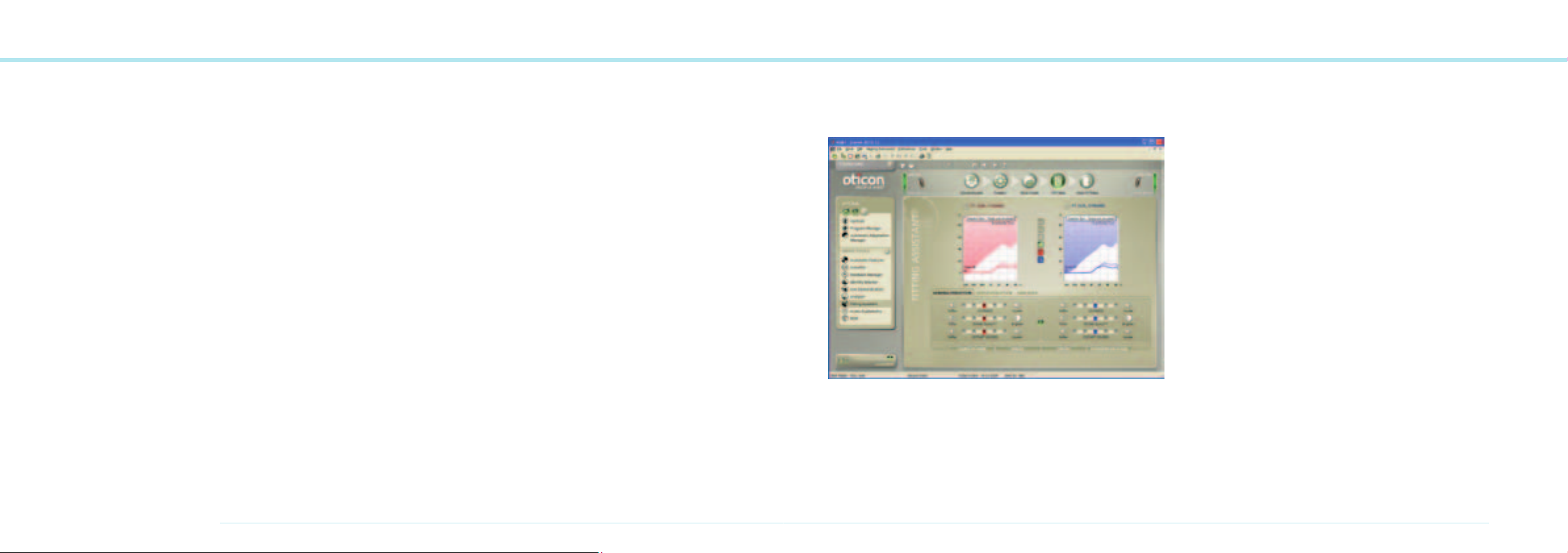
Fitting Assistant
Life Learning is a feature that helps the instruments adapt
to user preferences and sound environment over time.
The instruments will register the preferred volume setting in
specific situations dependent on level (Soft, Moderate and
Loud) and content (Speech, Speech in Noise and Noise) and
automatically adapts to the preferred setting.
Configuration: Under configuration you can disable Life
Learning and Memory by deselecting the checkboxes.
58
OTICON AGIL FITTING GUIDE
The Fitting Assistant is a tool designed to deal with common
problems that require adjusting the hearing instrument at
the fitting or follow-up visit.
To operate the Fitting Assistant, select the tab that expresses
the client’s complaint and then a control (such as Loudness).
Click the control to adjust it.
The adjustments made in the Fitting Assistant are immediately
visible in the graphs. When you open the tool in the future,
you can see how far from the starting point (the middle)
the controls have been moved.
The Fitting Assistant can be used individually for each program
in the instrument.
59
Page 31
In-situ Audiometry
Real Ear Measurements
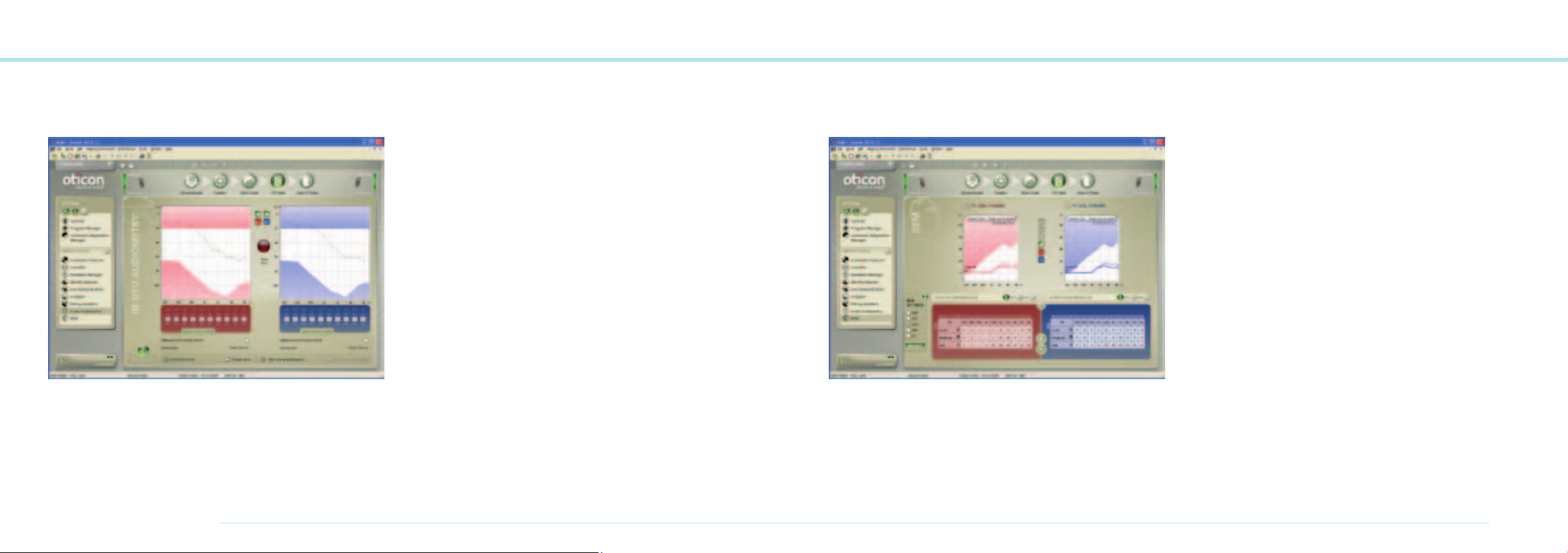
With Oticon Agil instruments, Genie supports in-situ audiometry for making precise fittings using the client’s own Molds
and hearing instruments during measurements of thresholds.
In-situ audiometry can be conducted between
250 Hz – 8 kHz, except for Open and Plus Domes where
the frequency range is 750 Hz – 8 kHz.
60
OTICON AGIL FITTING GUIDE
How to use in-situ audiometry
The layout of the tool resembles a standard audiometer.
In the Audiogram graph, you can see the normal audiogram
represented as a faded grey curve. If the instruments are connected, you can conduct in-situ audiometry by using the fields
below the graph to set the frequency and level of the tone.
Click the Play Tone button and the stimulus is played in
the instrument as long as the button is activated.
During measurements, instrument microphones are muted.
Click the Talk-Over button to switch on microphones and talk
to the client; click again to switch off.
Ambient noise level is measured by the instrument
microphones. In case of too much noise, the red noise level
indicator will light up.
The buttons in the lower right corner select whether you want
to use the in-situ audiogram to calculate settings in Genie or if
you wish to continue using the normal audiogram.
The Genie REM tool lets you verify your fitting by comparing
your Real Ear Measurement equipment with Genie.
Use the tool to activate or deactivate advanced features to
match the purpose of the measurement.
In order to compare your measurement to target and simulated
curves in Genie, make sure that the Genie curves are based on
the same signal type and level as measured.
Note: For custom instruments you cannot verify the Directionality when the programming cable is in the instrument.
Also, the response in REM can be affected by interference
of the programming cable.
61
Page 32
End Fitting
Buttons and Indicators
62
OTICON AGIL FITTING GUIDE
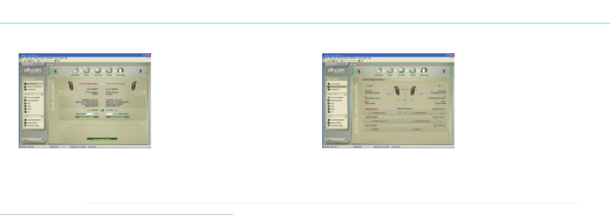
The End Fitting step covers all tools that are related to user
operations of the instrument as well as Streamer.
The Save and Exit screen contains information about the
Agil instruments. It also gives you the possibility to link
Streamer to the instruments.
To link Streamer to the instruments, click “Read serial number”
and follow the instructions provided on the screen.
If your instruments are connected via HI-PRO you cannot use
the automatic read-out. Instead you need to type in the serial
number of your Streamer.
You find the number in the silver area on the back of Streamer.
In the Button and Indicators you define the functionality of
the available buttons, volume control and beeps on the
instruments.
This is the place where you choose whether you want the
buttons to affect both instruments at the same time by clicking the Binaural Coordination button next to the operation you
want handled.
You have the option of including a Mute function in the
buttons. By default this is set to off. When turned on, the Mute
function can be activated by the client with a very long push
on the button.
63
Page 33

Double Button on BTE and RITE
Single Button on miniRITE
This switch can move the program cycle forward or backward
or the volume control louder and softer for each instrument.
Genie gives you the flexibility to program the switch for program changes, volume changes or both. You can also decide
with the client if the switch control should be programmed the
same to both hearing instruments. Some clients prefer to have
one ear be for volume while the other is for program changes.
What ever option is chosen, “binaural coordination” must be
enabled in Genie to ensure the changes are applied to both
instruments.
Instruct your clients to use a short push for program changes
or volume changes. If the instrument has been programmed
for both functionalities instruct the client to use a short push
for volume changes and a medium long push for program
changes.
In the User Instruction task you can print the button configuration and include it in the Instructions For Use to provide the
information for your client.
64
OTICON AGIL FITTING GUIDE
Beeps
The Beeps tab is used to define the audible alerts for program
and volume control changes as well as decide when there
should be audible alerts in the instruments.
Note: Remember to fill out the programmed button controls in
the Instructions For Use before handing it out to the client.
The miniRITE instrument has a single push button.
Having one instrument, the push button can be used for
switching forwards in the program cycle.
Having two instruments where the binaural coordination is
activated, the push button can be used for both adjusting the
volume and switching between programs. When the push
button on one instrument is activated it will change the status
on both hearing instruments.
Volume control is only available with miniRITE when fitting
two hearing instruments binaurally.
When binaurally fitted, the single button on the RIGHT instrument will increase the volume and switch forwards in the
program cycle and the single button on the LEFT instrument
will decrease the volume and switch backwards in the pro-
gram cycle.
Discuss with your client which operation should be included
in the instruments.
If you choose to have either the program change OR a volume
control in the button, this is activated by a short push on the
button.
If you choose to have both functionalities in the instruments,
then the volume control is activated by a short push on the button while a program change is activated by a medium-long push.
In the User Instruction task you can print the button
configuration and include it into the Instructions For Use to
provide the information for your client.
Beeps
The Beeps tab is used to define the audible indication for
program and volume control changes as well as decide when
there should be audible indication in the instruments.
Note: Remember to fill out the programmed button controls in
the Instructions For Use before handing it out to the client.
65
Page 34
Push Button on ITC (optional) ConnectLine
ITC instruments may have a push button. This page explains
the possible functions of the ITC push button. Having one
instrument, the push button can be used for switching
forwards in the program cycle.
Having two instruments where the binaural coordination is
activated, the push button can be used for both adjusting the
volume and switching between programs. When the push
button on one instrument is activated it will change the status
on both hearing instruments.
A volume control is only possible when fitting two ITC hearing
instruments binaurally. When binaurally fitted, the push button on the RIGHT instrument increases the volume and switch
forwards in the program cycle and the push button on the
LEFT instrument decreases the volume and switch backwards
in the program cycle.
Discuss with your client which operation should be included in
the instruments.
66
OTICON AGIL FITTING GUIDE
If you choose to have either the program change OR a volume
control in the button, this is activated by a short push on the
button.
If you choose to have both functionalities in the instruments,
then the volume control is activated by a short push on the button while a program change is activated by a medium-long push.
In the User Instruction task you can print the button configuration and include it into the Instructions For Use to provide the
information for your client.
Beeps
The Beeps tab is used to define the audible indication for
program and volume control changes as well as decide when
there should be audible indication in the instruments.
Note: Remember to fill out the programmed button controls in
the Instructions For Use
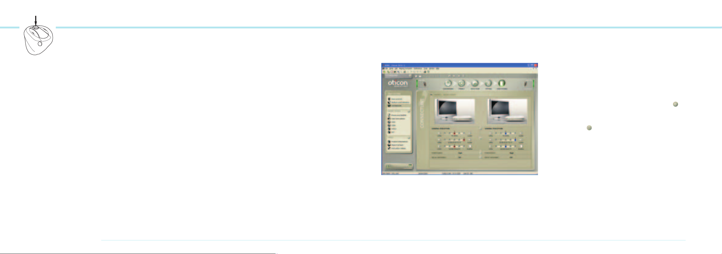
The ConnectLine tool gives access to the three dedicated
programs used for streaming applications. The applications are
organized under 3 tabs; TV, Phones and Music/Audio where
you can adjust several controls in order to fine tune the sound
experience according to client preferences. For each application, you can also set the preferred level and the relationship
between Streamer and microphone signals.
The adjustable controls are organized in 3 windows
• General Perception
• Power Bass
• Music Widening
One window can be opened at the time by using the
The controls are adjustable for the left and right instrument
separately. If the
in the specific window will automatically be applied to both
instruments.
Some of the features are not available for all applications.
In this case, the controls will be disabled (greyed out).
button is activated, your adjustments
button.
67
Page 35
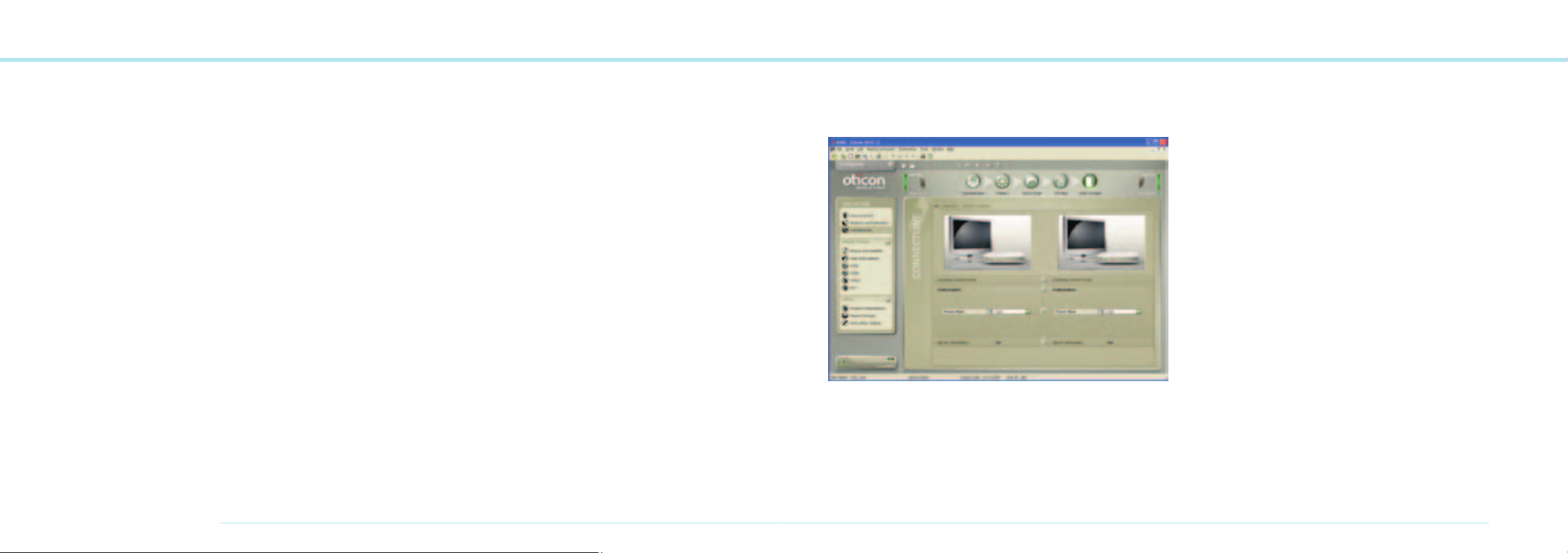
TV Program Tab
In the ConnectLine tool the following features can be adjusted
for each streaming application.
General Perception
Here, the general level of the streamed application is set and
also the hearing instrument microphone (M) level relative to
the application.
The ‘sound quality’ trimmer is used to correct the emphasis
of the audio response by adjusting the tonal balance.
The response can be made brighter (more HF) or fuller
(more LF) according to client preferences.
Power Bass
Provides the client enhanced bass dynamics and gives much
better LF response with open fittings. The Power Bass is
adjusted in 3 steps (High, Medium, Low) or can be set to ‘off’.
68
OTICON AGIL FITTING GUIDE
Music Widening
Creates a more spacious sound experience. The feature
requires two instruments and is based on reverberation
techniques. Like Power Bass it is adjusted in 3 steps
(High, Medium, Low) or can be set to ‘off’.
The TV Program Tab enables fine tuning of the ConnectLine
TV application.
General Perception
M rel. to TV:
Normally, the levels for the hearing instrument microphone
and the TV should be equal (0 dB) in order to easily hear
conversations when watching TV.
Power Bass
For improved TV experience the deep bass feature is normally
set to ‘High’.
Music Widening
For TV listening the Music Widening feature is default set
to off in order to optimize speech understanding, e.g.
from news broadcasts.
69
Page 36
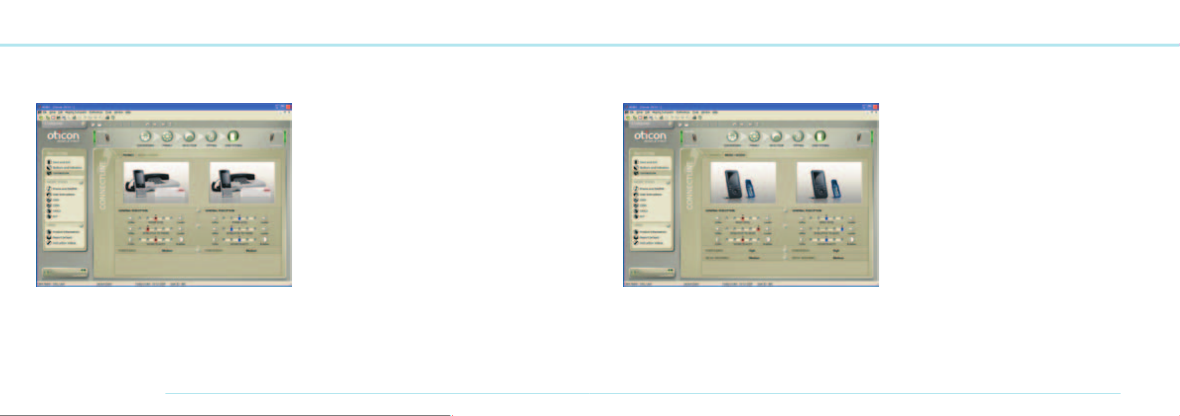
Phones Program Tab
Music/Audio Program Tab
70
OTICON AGIL FITTING GUIDE
The Phones Program Tab enables fine tuning of the
ConnectLine phone or/and cell phone applications.
The adjustments are applied to the instrument phone program
used for streaming and will be used for all ConnectLine phone
and cell phones connected to the client’s Streamer.
General Perception
M rel. to Phone:
Normally, the level for the hearing instrument microphone
should be lower (softer) than the phone in order to focus on
the phone conversation.
Power Bass
For the phone application the deep bass feature is normally
set to ‘Medium’.
Music Widening cannot be activated since it may reduce
speech understanding.
The Music/Audio Tab enables fine tuning of the wired input
and wireless applications, e.g. music players.
General Perception
M rel. to Music:
Normally, the levels for the hearing instrument microphone
and the music application should be the equal (0 dB) in order
to hear other relevant information from the surroundings
when listening to music.
Power Bass
For improved music experience the deep bass feature is
normally set to ‘High’.
Music Widening
For music listening the Music Widening feature is default set
to ‘Medium’.
If the Music/Audio program is mostly used for listening to voice
programs (books), the Music Widening should be set to ‘off’.
71
Page 37
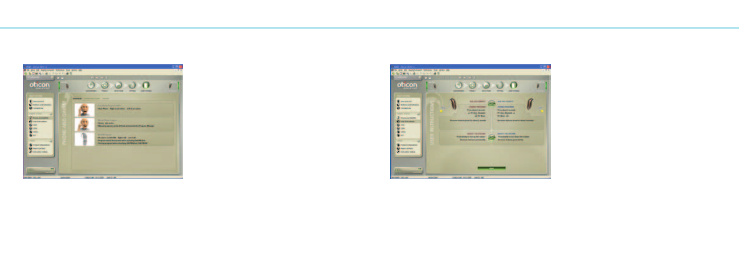
Phone and DAI/FM
User Instructions
72
OTICON AGIL FITTING GUIDE
The Phone and DAI/FM tool provides an overview of the phone
programs and it helps you to define the functionality of Auto
Phone programs and DAI/FM programs when relevant.
For Auto Phone programs you can enable or disable the
functionality and choose whether the program should be a
Microphone or a Telecoil program (when Telecoil is present).
On the DAI/FM tab you can choose to boost the DAI/FM signal
in situations where both DAI/FM and the microphones on the
instruments are active.
This tool indicates how the buttons are configured on the
Agil instruments. Use this tool to instruct the client in the
operations possible on each instrument. It is possible to print
the information for the client, so they can take it home.
73
Page 38
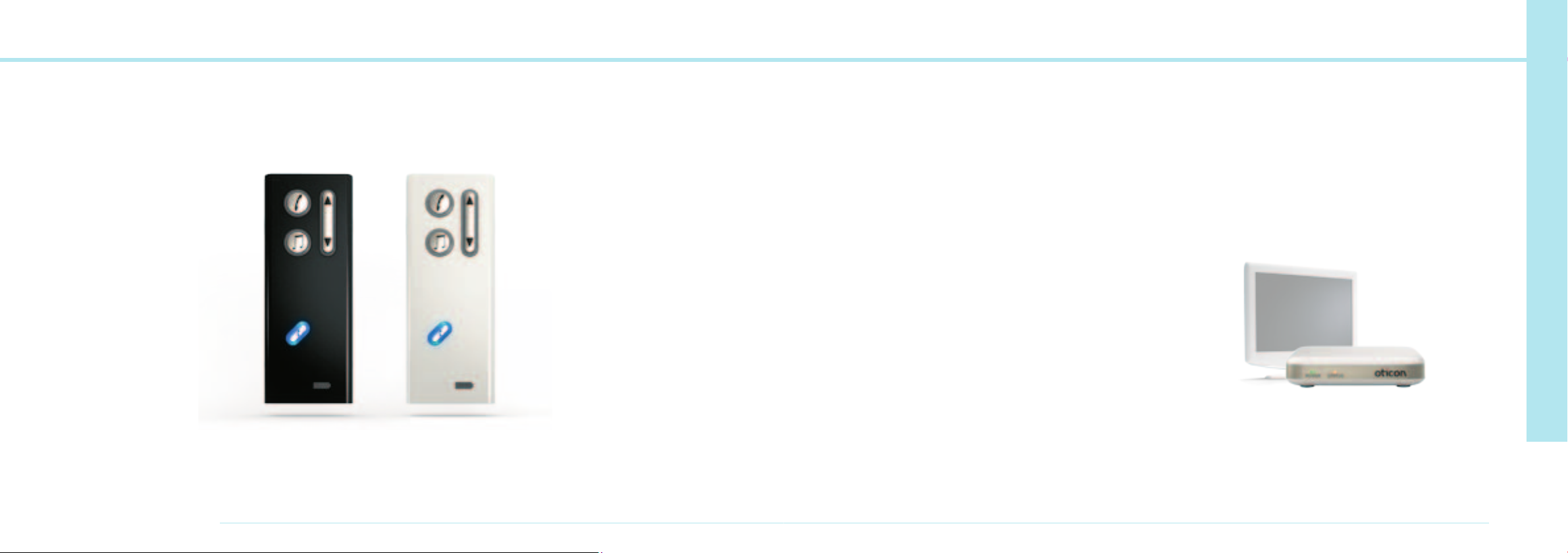
ConnectLineTM Concept
74
OTICON AGIL FITTING GUIDE
ConnectLine is an integrated system which enables HI users to
take advantage of, and benefit from, entertainment and communications better than ever before.
• Handsfree phone conversation on cell phones
• Handsfree conversation on landline phones
• Sound and music from TV, radio, music players, computers
and other devices
• Operate the volume control and program change on
the Oticon Agil instruments
Streamer wirelessly transmits sound from phones, TV etc. to
both hearing instruments thereby improving the overall sound
quality and speech understanding.
The TV Adapter wirelessly transmits sound from the TV
to Streamer.
8
75
Page 39
Pairing Guide and Daily Use
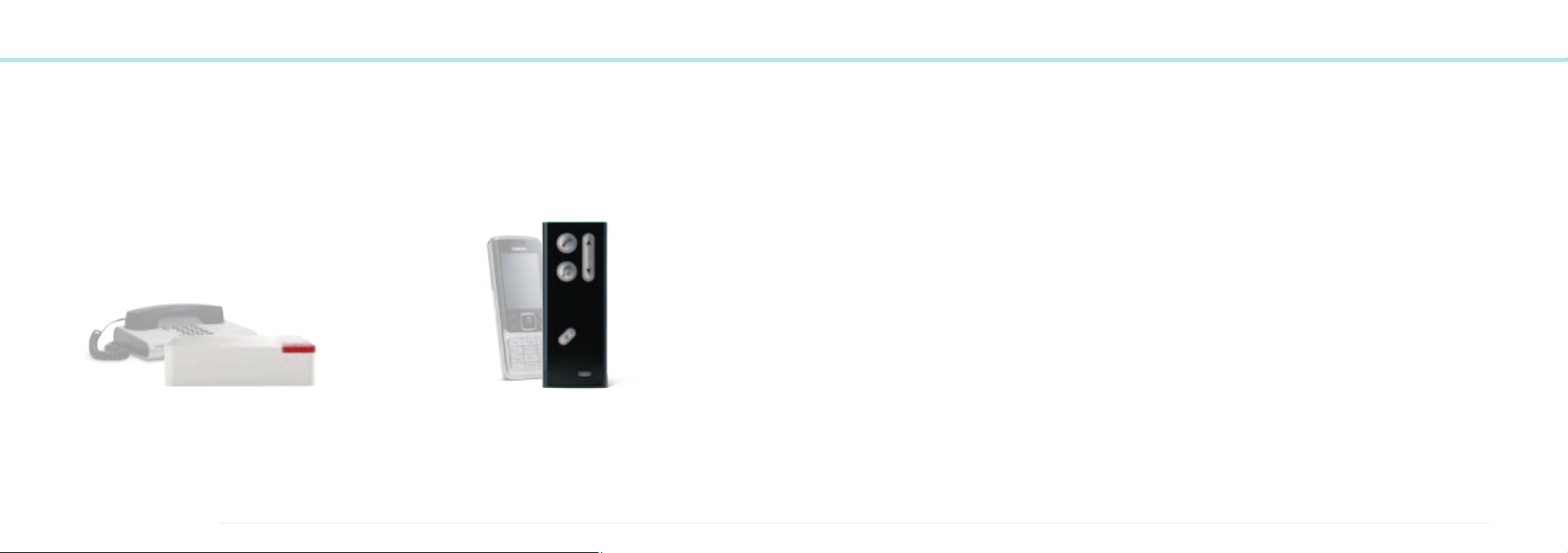
The Phone Adapter acts as wireless connection between
Streamer and a landline phone in effect turning the HI and
Streamer into a wireless headset for domestic use.
76
OTICON AGIL FITTING GUIDE
Streamer is both the remote control and the connection point
for all ConnectLine Adapters. Streamer connects directly –
through Bluetooh – to practically all modern cell phones.
Before using Streamer it has to be paired to the device it
should connect to. A wireless link is established between the
two units, enabling them to identify each other and communicate whenever they are turned on and within range of each
other. Pairing is done by placing both units into pairing mode.
The units automatically will search and find each other.
(please see the following pages for detailed pairing
instructions).
The neck strap is an antenna
Please pay particular attention to the fact that the neck strap
supplied with Streamer is an antenna which is part of the
advanced wireless system. For all other purposes than using
Streamer as a remote, the neck strap should be worn around
the neck.
Please note that the neck strap should never be opened.
The safety lock in the back is a feature designed to break if
the neck strap is caught in something. If the neck strap breaks
it must be replaced.
Generally, by daily use the neck strap eventually becomes
frayed and dirty and should be replaced regularly.
Adjusting Volume
Use the Up/Down button on Streamer to adjusting the phone
volume level in the hearing instruments. To adjust the volume,
press Up or Down shortly. Repeat the short press to do further
adjustments.
Note: The volume level when streaming set by Streamer is
memorized. Next time your client is watching TV/making
a phone call, the memorized volume level will be applied.
The memorized volume level is reset when the “Connect”
function is turned off.
Muting the hearing instrument microphones
When streaming an audio application, the hearing instrument
microphones are default active. To mute the microphones e.g
to pay full attention to a phone conversation press and hold
the Volume button for 2 seconds (up or down).
77
Page 40

Streamer and cell phones
Pairing
Pressing the Volume button for 2 seconds again activates
the hearing instrument microphones.
Note: the microphone state is memorized for each streaming
application by Streamer. Next time your client is watching
TV/making a phone call, the memorized microphone state
will be used.
The memorized microphone states are reset when the
“Connect” function is turned off.
78
OTICON AGIL FITTING GUIDE
Prepare the cell phones:
1. Refer to the manual of the cell phone for detailed instruction on how to conduct the pairing (normally, it is referred
to as “find new Bluetooth device”). Set up the cell phone as
instructed.
Note: For further information refer to the pairing guide located
on www.oticonusa.com
Prepare Streamer:
2. Assure that the key lock is deactivated.
3. Press the Streamer Connect button for 5 seconds until
the blue light starts flashing rapidly.
The two devices are now establishing a connection to
each other.
Cell phone handling:
4. When the cell phone has received Streamer information,
‘Streamer x.y’ will appear in the display.
5. Go to ‘Streamer x.y’ in the cell phone display and
press select.
6. You will now be prompted for a pincode: all Streamer pin-
codes are four zeros (0 0 0 0) – note, that just like for other
pincodes the 0’s most probably will appear as asterisks (*).
7. Streamer and the cell phone are now paired.
The pairing is done only once. If the phone is switched off or
the Streamer battery is drained, the units will remained paired
when turned on again.
Daily Use
Phone calls with Streamer
Streamer must be within 30 feet of the cell phone.
The connection must be active in order for Streamer and cell
phone to work:
Press and hold the Connect button for 2 seconds until the blue
light turns on. After one minute the blue light will automatically go into sleep mode (slowly fading on/off every 5 seconds)
to prolong battery lifetime.
79
Page 41
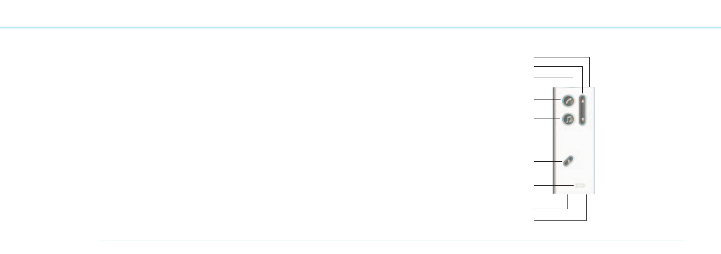
To turn off the blue light immediately, activate the key lock
slider.
Incoming calls
A ringing tone is heard in the hearing instruments and
the green rim light around the Phone button flashes.
Make a call
Use the cell phone to make the call (assuming that Connect is
on the cell phone will automatically connect to Streamer). When
the call goes through, talk into Streamer – do not press the
Phone button on Streamer.
Microphone
(Volume/program change) Up/Down
Key Lock
Phone
Answer
Press Streamer’s Phone button shortly. Streamer answers
the call and the green rim light will switch to solid light.
The call is now directed into the hearing instruments.
Talk in the direction of the microphone on Streamer.
Reject call
Long press on the phone button will reject the call.
Hang up
Press Streamer’s Phone button shortly. Streamer hangs up the
call, the green rim light turns off and the hearing instruments
return to the previous program.
80
OTICON AGIL FITTING GUIDE
Audio (TV/music)
Connect
Battery Indicator
Music Connection e.g. MP3
Power
81
Page 42

Streamer and the TV Adapter
(For installation of the TV Adapter refer to the Installation
Guide and Genie Instruction Videos.)
Pairing
1. In order to prepare the TV Adapter and Streamer as a pair,
the devices must be placed close together. Place Streamer
right next to the empowered TV Adapter (less than
30 cm /1 ft between devices. TV Adapter turned on).
2. Assure that Streamer’s key lock is deactivated.
3. Press Streamer Connect button for 5 seconds until the blue
light starts flashing rapidly.
4. The two devices are now establishing a connection to
each other.
5. Within one minute the TV adapter connects to Streamer
and pairing is complete.
— The orange STATUS indicator on the TV adapter shows
a solid light.
82
OTICON AGIL FITTING GUIDE
Pairing is done only once and will normally not have to
be repeated.
Daily Use
TV listening
Wear Streamer around the neck with the neck strap.
Streamer must be within 30 feet from the TV adapter.
START sound
— Press the Audio button shortly. Streamer connects to
the TV adapter.
— After a few seconds the orange solid light is shown on
Streamer and the TV adapter.
— The hearing instruments will receive the TV sound.
STOP sound
— Press the Audio button shortly.
— Streamer disconnects from TV adapter.
— All orange lights turn off and the hearing instruments
return to the standard program (P1).
Accepting phone calls while watching TV
An incoming call either cell or from the Phone Adapter will be
indicated by a ringing indicator. When the phone call is over
Streamer will return to the TV sound.
Note: The Connect function on Streamer must be activated to
allow transmission from the TV. If not active, it automatically
turns on when starting TV listening. Deactivating the Connect
function must be done manually with the Connect button.
83
Page 43

Streamer and the Phone Adapter
(For installation of the Phone adapter refer to the Installation
Guide and Genie Instruction Videos).
Pairing
1. Assure that Streamer’s key lock is deactivated.
2. Press Streamer Connect button for 5 seconds until the blue
light starts flashing rapidly.
3. Press the red Phone button on the Phone adapter for
5 seconds until the red status indicator flashes.
4. Within half a minute the Phone adapter connects to
Streamer and pairing is complete.
5. The red status indicator of the Phone adapter gives a solid
red light.
6. The blue light in the Streamer Connect button gives solid
light for 5 seconds and then shows slow fading light.
Pairing is done only once and will normally not have to be
repeated.
Daily Use
Phone calls with Streamer
Wear Streamer around the neck in the neck strap, and make
sure that the Connect function is active:
Streamer must be within 30 feet of the Phone Adapter and the
red status indicator on the Phone Adapter must show constant
light.
Incoming calls
A ringing tune is heard in the hearing instruments and
the green rim light around the Phone button flashes.
Answer
Press Streamer’s Phone button shortly. Streamer answers
the call and the green rim light will switch to constant light.
The call is now directed into the hearing instruments. Talk in
the direction of the microphone on Streamer. The red status
indicator on the Phone adapter flashes during the call.
Hang up
Press Streamer’s Phone button shortly. Streamer hangs up the
call, the green rim light turns off and the hearing instruments
return to the previous program.
— The red status indicator on the Phone adapter switches
to solid light.
Make a call
1. Press Streamer’s Phone button shortly (or shortly press the
red Phone button on the Phone Adapter). You will now hear
the dial tone in the hearing instruments. The green rim light
shows constant light in Streamer’s Phone button.
2. Pick up the phone/phone receiver and dial the phone
number.
3. Put the phone Receiver back down.
— The red status indicator on the Phone adapter flashes
during the call.
Hang up
Press Streamer’s Phone button shortly. Streamer hangs up the
call, the green rim light turns off, and the hearing instruments
return to the previous program.
— The red status indicator on the Phone adapter switches to
solid light.
Make sure that the phone is turned off, or the Receiver is
back on!
84
OTICON AGIL FITTING GUIDE
85
Page 44

Audio Streaming
Streamer can receive audio signals from radio, PC, MP3 players
or other devices.
Audio sources using Bluetooth can be paired to Streamer
to stream music etc. wirelessly. Other audio sources can be
connected by means of the Audio Cable. Communication from
Streamer to the hearing instruments will always be wireless.
Wireless Audio Input
Music from a stereo Bluetooth device is connected to Streamer
when:
— the two devices are paired
— inside the Bluetooth range (30 feet)
— When the music player (or other stereo audio source) is
turned on, streaming is automatically started via Streamer
and played in the hearing instruments.
Starting wireless audio streaming
Audio streaming can always be started from Streamer with
a long push on the Audio button. If no TV Adapter has been
paired to Streamer – then a short push on the Audion button
will also start streaming.
86
OTICON AGIL FITTING GUIDE
Note! This feature is only available in Streamer 1.3 or later.
To upgrade Streamer firmware to a later version please see
page 89 – 90.
Stop wireless audio stre aming
The audio streaming is ended by pressing Streamer’s Audio
button. The hearing instruments will return to the General
program (P1).
Wired Audio Input
When the jack wire connects from an audio player to Streamer,
Streamer will start streaming sound after the Audio button is
pressed.
Stop audio streaming
When the jack is removed or the Audio button is used to end
the audio transmission, the hearing instruments will return
to the General program (P1).
Accepting phone calls during audio streaming
(wired or wireless)
If a phone call is accepted while the audio signal is activated,
the phone call will have priority.
When the phone call is over Streamer will automatically return
to audio streaming.
87
Page 45
Streamer Firmware upgrade tool
How and when to upgrade Streamer
Wearing Streamer
Streamer should be worn with the neck strap. This enables
handsfree operation and undisrupted sound quality.
Battery
Streamer has a built-in rechargeable battery. The battery will
last up to 8 hours when audio streaming is active.
When the Connect function is active the battery will last for
60 hours. The battery indication will start blinking when the
battery is close to empty (about 5 minutes left) and an audible
signal will be sent to the hearing instruments.
Recharging the battery from empty takes approximately
4 hours. Streamer will work while being charged. When fully
recharged the battery indicator light is solid green.
Note: The green light disappears when Streamer is
disconnected from the charger.
88
OTICON AGIL FITTING GUIDE
Key lock
You can lock the keys to avoid unintended activation of the
buttons. The slider button on the top of Streamer locks and
unlocks the keyboard. This will also turn off the blue Connect
indication and reduce the other indicators light intensity.
Important! How to use the neck strap
As a safety device, the neck strap has a plastic shell that
automatically breaks if the strap gets caught in anything.
This safety shell is NOT a lock, and under normal use will
not be broken.
If the safety shell is separated or broken, the neck strap
must be replaced.
Do not shorten or modify the neck strap in any way.
For example, do not tie a knot in it to shorten it.
Please note! It is only recommended to upgrade a Streamer
for the purpose of providing additional client benefits.
If a client has a well functioning ConnectLine system an
upgrade is not advised.
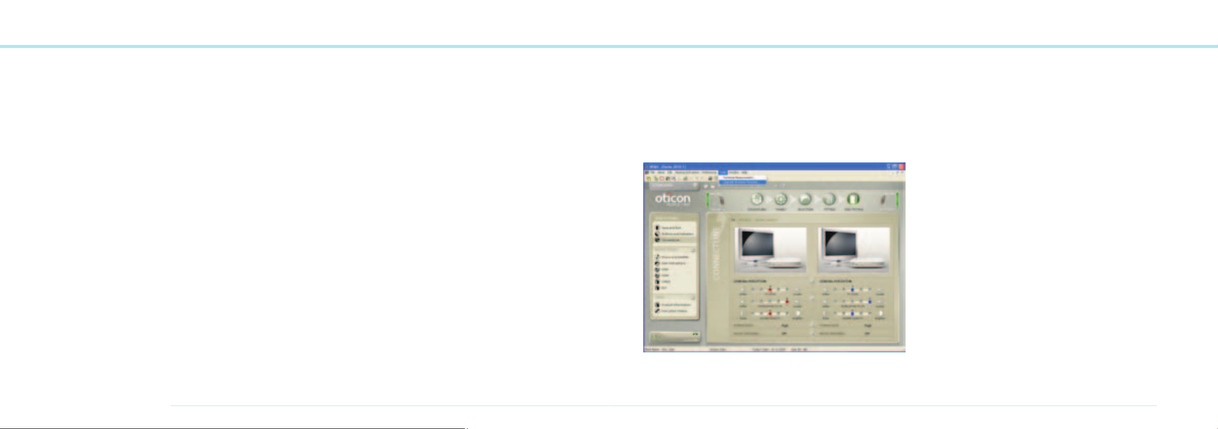
Selecting “Streamer Firmware upgrade” in the tools menu
gives access to upgrade a Streamer to the latest available
version, without losing existing pairings.
Connecting Streamer to the PC
1. Connect the large end of the USB cable to an available
USB port on the computer.
2. Press and hold the Up button on Streamer,
3. Connect the small end of the USB cable to Streamer.
When Streamer is connected, the current firmware version
in Streamer is displayed and whether this firmware can be
upgraded to a newer version.
In the bottom of the upgrade window there is a link to
“Upgrade Information”. This will open a .pdf with up-to-date
information about the differences between Streamer FW
releases on the market today. The document also has an
overview of the different push button functions in the latest
release.
89
Page 46
Service and Maintenance
Domes
Charging
Note! Streamer battery cannot charge while the upgrade is in
progress. If Streamer battery this level is too low, upgrading
can’t be started (UPGRADE button is disabled).
Upgrading
When Streamer is connected, sufficiently charged and the
firmware in Streamer is older than the newest available, it is
possible to start the upgrade. Press the UPGRADE button.
During the upgrade, the green bar expands to the right and
when completed a window pops up.
90
OTICON AGIL FITTING GUIDE
Before you start the upgrade note the following:
• The upgrade may take up to 20 minutes. The PC and Genie
can still be used during the upgrade.
• Do not disconnect the USB-cable during the upgrade.
• Do not let your computer go into standby or shut down
during the upgrade.
• If you are using a laptop, run it on AC power during
the upgrade.
• No existing pairings will be lost.
A wax filter is integrated into all types of domes.
The domes must be replaced regularly or whenever needed.
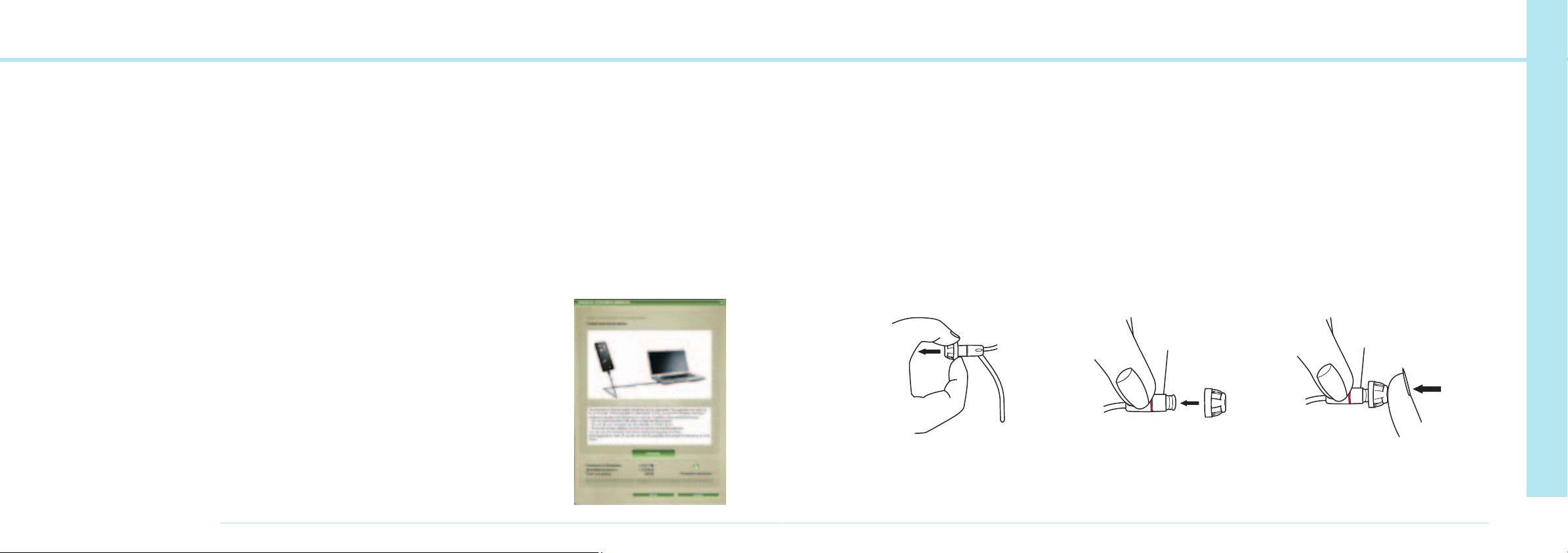
1 2 3
Replacing the dome is easy
Take off the old dome using your finger nails. Push the new
dome onto the Receiver. Give it a push to secure it safely.
Make sure that clients have extra domes when relevant.
9
91
Page 47
Damper
NoWax
The Damper is placed in the hook on BTE instruments.
It mainly works as an acoustic filter, shaping the frequency
response, but also has a function of preventing moisture and
cerumen from entering into the instrument.
If there is no sound in the instrument or the sound output is
reduced, it may be caused by a clogged Damper and it must
be replaced.
Replace the Damper as shown.
Notice: The Damper is not used with BTE Power instruments.
92
OTICON AGIL FITTING GUIDE
1 2
3 4
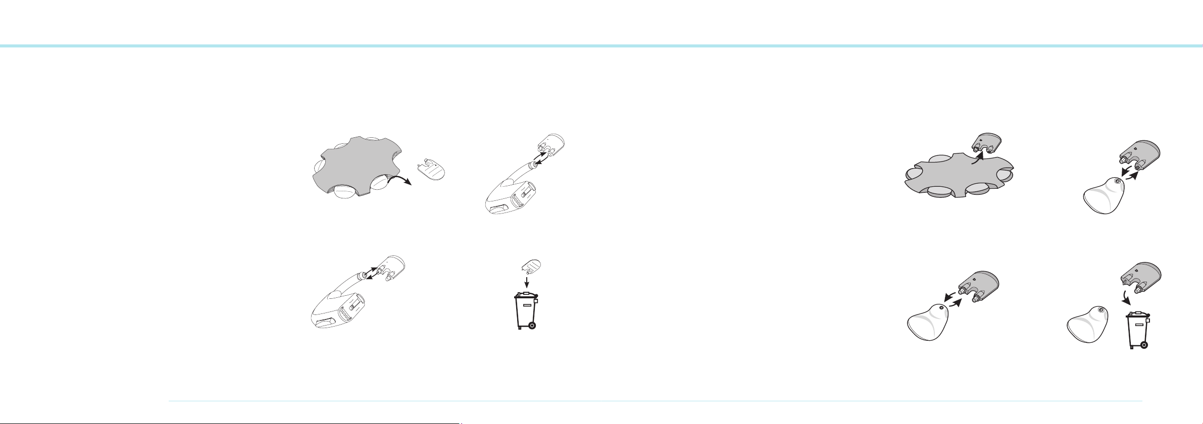
Wax protection system for:
— ITE instruments
— ITC instruments
— RITE Power Molds
— Standard Receivers
— Medium Receivers
Replace the wax filter in case it is clogged
or if there is no sound in the instrument.
1 2
3 4
93
Page 48
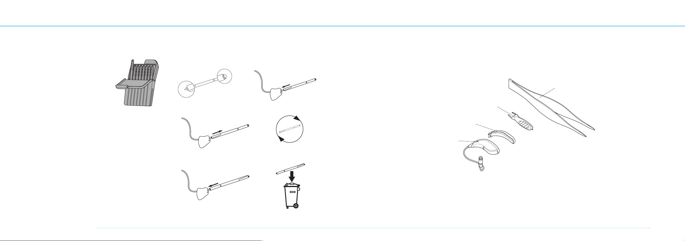
miniRITE top shell exchange
WaxStop
Wax protection system for:
— Power Receiver Adapters
— RITE Molds
Replace the wax filter in case it is
clogged or if there is no sound in
the instrument.
Necessary tools
1
A
B
3
5
2
4
6
180
Tweezers
Multi tool
0
(pre-assembled with push button)
Oticon Agil miniRITE
New top shell
94
OTICON AGIL FITTING GUIDE
95
Page 49
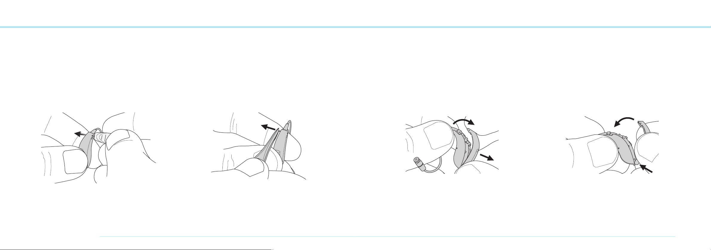
1. Push locking pin
Push pin out with multi tool.
2. Remove locking pin
Remove the locking pin with tweezers.
3. Removal of top shell
Remove the top shell.
4. Mount new top shell
Mount the new top shell. It’s important to mount the top
shell in the bottom end first and then rotate the top shell
in place.
2
1
96
OTICON AGIL FITTING GUIDE
97
Page 50
Changing battery door on miniRITE
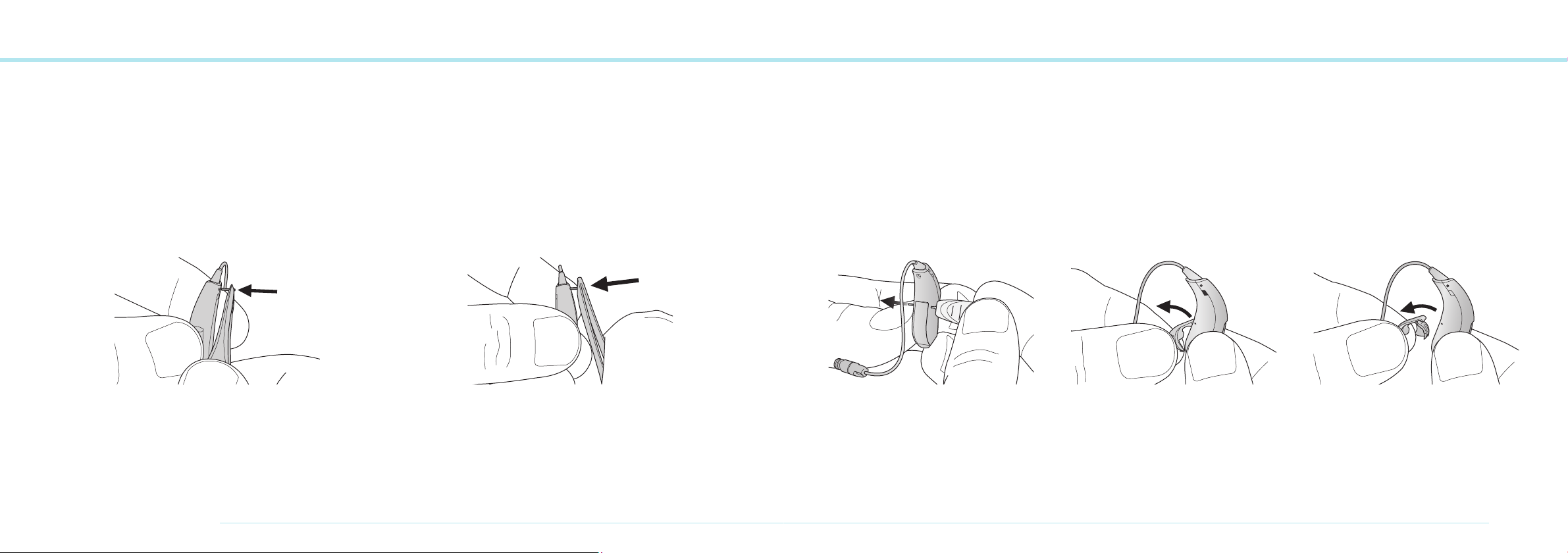
5. Insert locking pin
Insert the locking pin with tweezers.
98
OTICON AGIL FITTING GUIDE
6. Position locking pin
Finally push the pin in position, use the back
end of tweezers.
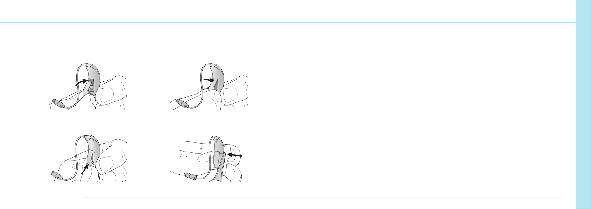
The battery door can be exchanged if damaged or
if a tamper-resistant door should be installed.
Battery door OFF:
1 2 3
99
Page 51
FAQ’s
Battery door ON:
1 2
3 4
100
OTICON AGIL FITTING GUIDE
1. How often should the Domes be changed? If the Dome is
not replaced from time to time it will get clogged with wax.
Replace whenever needed. For most users this will be once
every one or two months. A package of Domes is enclosed
with the device. Advise your clients how they can obtain
replacement domes.
2. When should I change the NoWax in the Receiver unit?
Visually inspect the NoWax filter for wax. Replace if wax
is present or no sound is coming from the device. See No
Wax package for instructions. Oticon recommends that the
Hearing Care Professional replaces the NoWax filter.
3. How often should the WaxStop in custom RITE Molds
be changed? The WaxStop should be changed whenever
needed. For most users this will be once a month.
If the client complains that there is no sound, replace
the WaxStop first.
4. Why does the Receiver unit need two different wax
filter systems when using a Custom Mold? The WaxStop
on the Receiver unit is part of the locking mechanism for
RITE Molds and does not need to be changed or removed.
The client need only change the WaxStop.
5. How frequently should the Receiver unit be changed?
The Receiver unit is designed to function for a long time
(several years), if it is cleaned properly. The Receiver is
an integral part of the device and should be removed
or
replaced if broken. The user should not remove the
Receiver.
6. Can the hearing instrument be damaged if an “M”
Medium Receiver is attached to EPOQ, VIGO or HIT
instruments? The Receiver will fit however you will not be
able to program it in Genie. There will be a greater output and you could damage the client’s hearing. It is very
important the Receiver is checked when they are attached
to the hearing instruments to ensure proper gain and
output requirements. Only ‘S’ marked Receivers may be
used for Epoq, Vigo and HIT RITE instruments and only ‘P’
marked Receiver may be used for Epoq and Vigo RITE Power
instruments.
101
10
Page 52

7. Can speakers from EPOQ, VIGO or HIT be fit to
Oticon Agil?
From Genie 2010.1 you have to select an “S” “M” or ‘P”
Receiver type when the Agil RITE instrument is selected.
The old Receivers will be phased out and should in
the meantime only be used for Epoq, Vigo and Hit RITE
instruments. If no other receiver is available, the old
receiver can be fitted as a Standard (S) and old Power
receivers can be fitted as Power (P) for Oticon Agil.
8. Can existing micro Molds be used with Medium
Receivers from Oticon Agil?
No, the M-Receiver size is slightly larger and will not fit
into old micro Molds.
9. Can RITE Standard, Medium and Power Receivers
be combined in case of an assymetric hearing loss?
Yes, different Receivers can be used with a binaural
RITE fitting.
102
OTICON AGIL FITTING GUIDE
Page 53

People First
People First is our promise
to empower people
to communicate freely,
interact naturally and
participate actively
100622 / 02.10 Printed in Denmark
on FSC™ 100% recycled paper, Cert no. SW-COC-004246, www.fsc.org
www.oticonusa.com
 Loading...