

Page 1
WORLD'S FIRST MULTI-BAND TRANSCEIVER
MODEL
(TX, RX., RPR OR TR) FOR 315, 434, 868, 915 BANDS
NEW
PRELIMINARY
1.25 X 1.25"
FREQUENCY HOPPING FOR OEMS & ENDUSERS
*Up To 100mW Output
*Up To 1000ft. Range
*1µA Stand-By Current
*4 Inputs and 4 Outputs
*Virtual WireTM Mode
*Quick to Worldwide Market With
Same Unit
*High R.O.I.
*3-24VDC & 90-265VAC Power
*7 Packages, Naked to E.Proof
DESCRIPTION
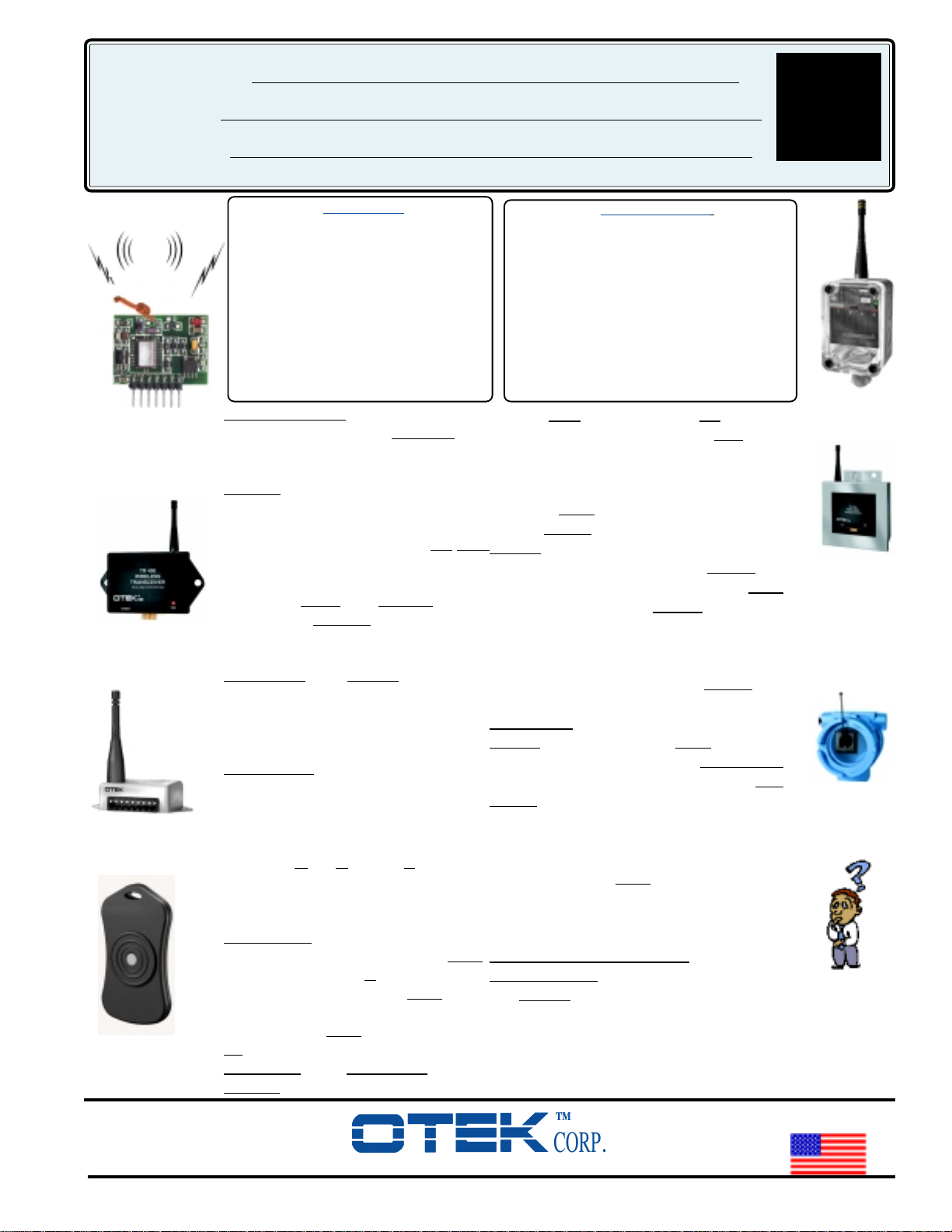
P.C. Mount
Finally a truly universal
system that complies to any country's
R.F. requirement! OTEK's new
MBTR can be ordered with any
1.5 X 1 X 3"
power, band, and operation as permitted by the country that is in use. This
means that your product does
to be changed at all! The same
P.C.B. and I/O are used for all bands
and due to
program the
Plastic Panel Mount
permissible bands, output power, and
operational mode (see License).
The T & R: The MBTR is available
as transmitter only (T), as receiver
only (R), as a repeater (RPR) or as a
transceiver (TR). As a "T" the unit
1.5 X 1 X 3"
accepts up to 4 different inputs from
dry contacts or push buttons (keyfob)
or 3V logic and transmits the "ON" or
"OFF" state of the inputs individually
Metal Panel Mount
coded. As an "R" the unit decodes the
specific input data and turns "ON" or
"OFF" its
(O.C.T.), its 3V TTL logic, or its relay
(depending on the output type you
select).
The "RPR": The repeater almost
doubles the range per unit. The "
can also be used as "
receiving function so any "
be used as an Alarm/Data originator
and the other "
Key-FOB
Transmitter
ID and data to the master receiver.
The "TR": As a transceiver (TR) the
MBTR is available in 2 versions.
520-748-7900
FAX: 520-790-2808
E-MAIL:[email protected]
http://www.otekcorp.com
FEATURES:
Wireless
not need
FCC rules OTEK must
MBTR for the specific
Open Collector Transistor
RPR"
T" overriding its
RPR" can
RPR"s as relays of the
SINCE 1974
APPLICATIONS:
*GPS Tracking *AMR *Silos *Cranes
*Hazardous Areas *Security Products
*Heating-Cooling *Pressure *Flow Rate
*Under-Over Voltage *Frequency *pH
*Event *%RH Controllers *Level *Serial
Communication *Pumps, Conveyors, Motors *Cargo Ships, Trailers *Smoke, CO, LPG,
Methane I.R. Gas, Detectors, Tally Polling,
Battery Operation
A. With
microcontroller. This means that
SPI (4 wire) I/O and No
you write
your own program with OTEK's
instructions and benefit from propriatory de-
sign and lower cost, but you'll have to get
your own
B. With
FCC license.
UART I/O, in this configuration the
MBTR does all the work for you, all you
need to do is interface it to your
follow OTEK's list of commands.
license is propriatory to
OTEK and OTEK
UART and
FCC
transfers it to you at no cost upon receipt of
your PO, payment and affidavit of use. This
will save you thousands of dollars and months
of bureaucratic red tape. The
be disabled to use as Virtual Wire
UART can
TM
.
LICENSE:
OTEK only licenses the FCC approved
bands and output power per
(902-928MHz, soon for 2.4GHz) or
Part 15.247
Part
15.231 (315 and 433MHz periodic operation). Any other non-FCC approved band or
power ordered must be accompanied by an
officer's signed affidavit that the unit's will
not be used within
FCC regulated areas and
that the user is responsible for obtaining the
license from the country/countries to be exported to.
No Affidavit-No Order Entry.
How it works:
The
MBTR series uses internally controlled
frequency hopping technique and programmable output power P.A. as well as error
checking to insure reliable communication
over the specified range. For extended
ranges it is permissible to increase the gain
4016 E. TENNESSEE ST.
TUCSON, AZ. 85714 U.S.A.
MADE
IN
USA
MBTR
2 X 2.5
X 4"
NEMA 4X
Panel/Pipe/
Conduit Mount
3 X 6 X 6"
Sanitary to
2500F Steam
Panel/Pipe
Mount
4 x 5 x 5"
Explosion
Proof
If You Don't
See It Ask
For It!
Page 2

MBTR Page 2
of the unit by using a higher gain antenna than the unity
gain supplied (contact OTEK for more information).
Since the MBTR has "room to spare" on the "TX" mode
when in the 902-928 FH band (100mW at present), one
could use an antenna with up to 20dBM for the "TX" or
"RX" without infringing the law. No restrictions apply to
the receiver's gain except for noise amplifications. Consult FCC at www.fcc.gov for further details.
The Packages:
"T": The transmitter is available in these packages
A.
and with these input configurations:
A.1.
“Naked” P.C.B. with 14 position header to
solder or plug in your P.C.B. measuring 1"x1"x0.3"
(25x25x8mm) with either
A.1.1 Soldered helical antenna (unity gain) or
A.1.2 With
supplied
RPSMA connector to screw the
WHIP antenna (unity gain standard).
The helical antenna increases the length to
1.7” (43mm) for 868 and 915MHz bands
and 2”(50mm) for 315 and 433MHz bands.
The WHIP antenna increases the length by 4”
(100mm) for 868 and 915MHz and by 6”
(150mm) for 315 and 433MHz. The antenna
connector (RPSMA) allows you to install the
antenna remotely from the MBTR but you’ll
loose about one (1) dBm per every 3ft (1M)
of coax cable. In the Naked configuration the
MBTR-“T” only accepts either dry contact
or 3V compatible logic.Power input is limited
to either 3V (2.75-3.3V) or 4 to 12VDC.
A.2.KeyFob: In this package the MBTR-”T”
contains its own 3V lithium battery in a key chain
module only 1.25x2.25x.4” (32x57x10mm) with
four (4) buttons. Battery life expectancy depends
on the usage (frequency of use and output power)
but normally is good for about 1000 operations at
intervals of 15 minutes for a duration of 5 seconds
or less.Only "M" & "L" modes are available. See
Note 2.4
A.3.Miniature Case: (Plastic or Metal):
Antenna: WHIP only screwed into the built-in
RPSMA connector
Power: 3, 4-48VDC and 90-265VAC
Inputs: Dry contact or 3V logic (others on request)
Mounting: Panel or chassis mount only
1x1.5x2.75” (25x38x69mm).
A.4.Nema 4X: Only 2x2.5x4” (50x63x100mm) and it
is wall, pipe, or panel mount. The 868 or 915
MHz antenna extends the 4” length to 8” (200mm)
and 315 or 433Mhz by 6” to 10” (250mm).
Power and inputs are the same as for the
miniature case (others on request).
NMH: (3A/Hr.) Battery Pack is optional.
Duration depends on the power and frequency of transmittion (typical 3+ years).
A.5.Sanitary: This case complies to Steam
Wash Down requirements and withstands up
to 250ºF (120ºC) steam or hose down. The
antennas extend the height by 4 or 6” (100 or
150mm). The all aluminum, water tight 3x6x6
(75x150x150mm) case can be wall, pipe, or
panel mount and has space for up to 3 units.
A.6.
Explosion Proof: This 5” (125mm) diameter
case only 4” (100mm) deep can be pipe or
wall mount. The
MBTR is inside and
coupled to the antenna on the tempered glass
with OTEK’s exclusive high throughput
technique retaining the agency’s classification
for Class I, Div 1&2 Hazardous Environments. The antenna swivels 360º for proper
orientation and the 1/2 NPT ports (2) can be
used to mount it or use the ears. There is
space inside the E.P. for OTEK’s
NMH
battery pack (4.8V @ 3AHR) for many
hours of operation since the MBTR-“T”
only consumes 1µA during stand by, 8mA
during awake and 70mA worst case at
maximum output power (25mA Nominally.
A.7. Batteries: How long do they last? How
often will the MBTR-T transmit? How big is
the battery? OTEK’s BP-48-4 is a 4 battery
pack with NMH batteries of 3A/hr rating,
enough for a minimum of 42 hours of continuous (?) operation (3000/70 mA) at maximum
power or more realistic over 365 days at 50/
day for 5 seconds at medium power. The
battery charger (p/n BC-48-4) is available
and don’t forget extra batteries p/n NMH1.23 (requires 4 each). The battery pack can be
included in NEMA 4X, Sanitary and explosion Proof (See Ordering Information.
B. “R”: The receivers use the same board as the
“T” with the same pinout except the inputs
become outputs. The "R" has 4 miniature LEDs
on the back that are lit when the transistor outputs
are low.
B.1.Naked: Same options and restrictions as the
“T” (see A.1.).
2
Page 3

MBTR Page 3
B.2.Miniature Case: You have the option of either
O.C.T. or relays. On the relays you have the
option of either normally closed (N.C.) or normally open (N.O.) contacts due to pinout count.
Power: 3V only for
and 90-265VAC for either relays or
NEMA 4X Case: Since all we do is install the
B.3.
O.C.T., Isolated 4-48VDC
O.C.T.
miniature case inside the NEMA 4X case, the
same options and restrictions of the miniature
case (see B.2) apply (also see A.4).
Note: On special request the NEMA 4X can be
fitted with 4 each SPDT 10 amp relays, contact
OTEK.
B.5.
Sanitary Case: Again we install the miniature
case (up to 3 ea.) inside the sanitary case, consequently all the options and restrictions of the
miniature case (see A.3 and B.2) apply.
B.6.Explosion Proof: (see A.6): The same features
of the E. P. for the “T” apply here except we
don’t recommend the battery pack with the relay
option since each relay consumes about 50mA @
5VDC. The “R” should always be “ON” (about
7mA) unless you control it for “stand-by” and
“wake-up”.
B.7.Batteries: Not recommended for “R” (see A.6)
but if you must, specify at time of ordering (see
A.7).
Warning: You CANNOT change frequency band
and output power. It is done at the factory due to
FCC and antenna matching.
C. Repeater (RPR)
Repeater: In this mode, the MBTR receives data on
one frequency channel and transmits it in another in
almost Real Time except for the latency and limited by
the Data Rate (see specs.). This configuration is useful
for doubling the range and/or "Mesh" communication
techniques thanks to the frequency hopping of the
MBTR. The "RPR" can be automatically switched
from "RPR" to "T" when any one of its 4 inputs is
driven "Low" forcing the unit to transmit its ID (Location) and alarm input type (If only I.N.S. would listen,
we could detect illegal border crossers "Pronto") to
other RPR to computer or satellites.
D. “TR”: The “TR” (Transceiver) uses the same PCB as
the “T” or “R” except we populate it differently. If it is
ordered for SPI I/O (Option S) we don’t install the
micro, if ordered with UART (Option M) and/or
other options such as A/D, we install the
microcontroller and program it as required.
Pinout: We use the same pinout as the “T” and “R”
as much as possible so you don’t have to change your
PCB except for some possible jumpers if you use all
4 versions on your same product.
SPI: (Option "S") In addition to the 4 SPI I/O
D.1.
the “TR” gives you access to other control pins
of the internal microcontroller in the R.F. chip,
such as valid data or interrupt input, clock out
(to synchronize your uC), FIFO interrupt or data
filter input or received data clock out, FIFO
select input or received data output or FSK data
input. With the SPI you can control, among
other things, the “low bat” detection threshold,
sleep, stand-by, and wake-up, status register,
P.O.R., 2 each 8 bit register for TX and 16 bit
for RX. Sorry, you
cannot change the band,
center frequency, bandwidth or higher output
power but you can change down power (TX)
and the sensitivity of the LNA (as RX). Refer to
user’s manual for more information or get the uC
version, it’s all done for you or OTEK can
customize it to your needs. Don’t forget, all I/O
are 3V logic!
µµ
D.2.
µC (Option C): Here we do it all for you! All
µµ
you need is a 3V logic compatible I/O. This
version has many forms of operation all via
simple configuration commands and if you don’t
have a UART compatible I/O you can disable it
and use the pins as data input and output. Some
functions are:
D.2.1.Virtual WireTM: Whatever you put at the
input, you’ll get at the output (3V logic).
D.2.2.*Latched: A “logic 0” or dry contact
close at the inputs (4) will latch the
receiver’s output until a general Reset
command is sent or the “RX “ manually
reset, but you must configure the units for
either TX or RX.
D.2.3.Start-Stop: The first “logic 0” pulse at the
TX will send an “ON” command to the RX
for that specific channel (1 of 4), the second
pulse will send a reset command to the RX
for that channel.
D.2.4.*Momentary: On falling edge (or contact
closure) at the input, the "TX" will transmit
the “ON” signal to the "RX" for it to turn its
corresponding output “ON” (1 of 4). On
the rising edge (or contact opening) the
"TX" will transmit the “OFF” command for
the “RX” to reset its output(s). That is why
we call it Virtual WireTM!
* = Only Available modes in "Key-Fob" case.
D.2.5. 10 Bit A/D: The "MBTR" has a 4
channel 10 bit A/D that can be enabled to
measure (as a "TX") and transmit the
wireless data to the "RX" for it to output it
in digital format through its UART port.
A simple command enables/disables the
3
A/D or converts it to digital I/Os.
Page 4

MBTR Page 4
D.2.6
Counter: A 16 Bit UP/Down Counter/
Timer is available so you can use it as
required or as a PWM with external
circuitry. Again, one MBTR should be
configured as "TX" and another as "RX".
D.2.7 FIFO: Almost like our Virtual WireTM but
you can transmit and receive in "Bursts" up to
8 bit wide and yu can do it in a two way
mode by switching the MBTR from TX to
RX upon completion of data sent. Remember
that the
MBTR has 2 each, 8 bit storage
registers. The first to store incoming data and
the second to store outgoing data (FIFO).
This can also be used to store "Preamble" and
ID data.
D.2.8 Custom Configurations: OTEK will be
happy to customize your confidential
propriatory firmware requirements as well as
hardware, whether it is one piece or millions.
All of our customers are important (we do not
check your size).
D.2.9 Package: As of this writing, the "TR"
version of the MBTR is only available in
"Naked" configuration for OEMs with
either helical or whip antenna and 3V or 4
- 12VDC power. Consult OTEK for other
packages.
PRELIMINARY SPECIFICATIONS @ 3V, 250C
AMBIENT WARNING: "ESD"
NOTE: See important footnotes that apply to each
version as well as the description of Sections A, B, C and
D and Ordering Information.
"T" (Transmitter Only: (See General Specifications)
*Input Level: 3V Logic with 47K pull up. NOTE: Never
exceed the suppply voltage!
*Input Channels: Four (4)
*Power Consumption: Stand-By: 1µA, Idle: 5mA,
Transmit: 25mA (maximum power)
*Power Supply Input Range: See Ordering Information
and footnotes.
"R" (Receiver Only): (See General Specs)
*Outputs: O.C.T. active low, 30V, 30mA sink
(2N3904), 3V Logic Outputs: Active High, 2mA
Source, Sink: 3mA.
*Output Channels: Four (4)
*Power Consumption: Stand-by: 1µA, Idle: 5mA,
Receiving: 15mA
*Power Supply Input Range: See Ordering Informa-
tion and Footnotes.
4
"P"or "S" or "C" Repeater or Transceiver
Only":
(See General Specs)
*Inputs & Outputs Levels: 3V logic (Dry Contact OK)
*Switchover Time (TX to RX): 500µS, (RX to TX):
400µS
*Power Consumption: RX 15mA, TX: 30mA, Idle:
5mA
GENERAL SPECIFICATIONS
(ALL VERSIONS)
*Carrier Modulation: FSK Frequency Hopping
(where applicable)
*Bandwidth (Center): 311-319: (315); 331-439:
(433), 861-879 (868), 901-929 (915)
*# Of Hopping Channels: 50 per Part 15.247
*Max. Data Rate: 57.6Kbps, 256Kbps on request
*Agency's Compliance: FCC, ETSI (For Unlicensed
Operation) (*1)
*Crystal Frequency: 10MHz (PLL, AFC & AXAC)
*Antenna Drive: Differential, Self-Tuning
*Low Noise Amplifier (LNA): Programmable to 0,
-6, -14 & -20dB
*Data Registers: TX: 2 ea. 8 Bit, RX: 1ea. 16 Bit
(FIFO)
*Wake-Up Timer: Programmable from 1mS to 31
days or On Request
*Power Supply Range: 2.8 to 5.2V (*2)
*Power Consumption: See Individual Versions (T, R
or "X") and Ordering Information
*Typical Ranges (Limited by Agency's Regulations)
(*1)
315MHz: Indoor: 300 Ft. L.O.S.: 1000 Ft.
433MHz: Indoor: 300 Ft. L.O.S.: 1000 Ft.
868MHz: Indoor: 500 Ft. L.O.S.: 2000 Ft.
916MHz: Indoor: 500 Ft. L.O.S.: 2000 Ft.
*Low Battery Detector: Programmable in 50mV
steps from 2.5-5V
*Logic Levels: Low: <1V, High: >2V
*Digital Inputs Current: <1µA, Digital Outputs Current:
<2mA
*Receiver's Sensitivity: -109dBm
*Transmitter Output Power Range: 20 to -20dBm
factory set for maximum allowed by agency for band
used, down programmable (*1)
*P.O.R. 100mS max.
*SPI: To Industry's Standard(S)
*UART: To Industry's Standard (ASCII) (C)
*3V Logic (Non-UART): Unrestricted (Virtual WireTM)
*Programmable Addresses (ID): 256 (Option "C")(*3)
*Polling (RTS): 1-9 Readings (Option "C") from RX to
TX
*A/D: 10 Bit Resolution, 0-2VDC F.S. Input (Option
"C")
*Transceiver's Operating Modes: See Par. D.2 Field
Configurable
NOTES: (S) = SPI Version, ("C") = µC Version, (T)
= TX Only, (R) = RX Only, (TR) = Transceiver, (P) =
Repeater
Page 5

MBTR Page 5
IMPORTANT NOTES:
(*1) = OTEK only supplies licensed units compliant to FCC for use in U.S.A. For Bands 315, 433 and 915MHz,
restricted per Part 15.247 & Part 15.231. It is your responsibility to comply with the LAW. Per Part 15.231 (315
& 433MHz Bands), You
Should NOT Transmit: Voice, Video, True Variable Data or transmit more than five (5)
seconds. See www.FCC.gov
868MHz versions are NOT permitted in U.S.A. (as of this writing). OTEK does not hold a license for any other
Country or is responsible for the use of its products. Orders of versions outside
FCC regulations (for other Countries use) must be accompanied with an Affidavit of "Not For Use Within U.S.A. or its Possessions" or the P.O.
will be rejected.
(*2) Power supply range is for 3V nominal
(*3) All units shipped with default address 000000 unless specified at time of ordering (field selected).
MECHANICAL DATA
5
Page 6
PRELIMINARY
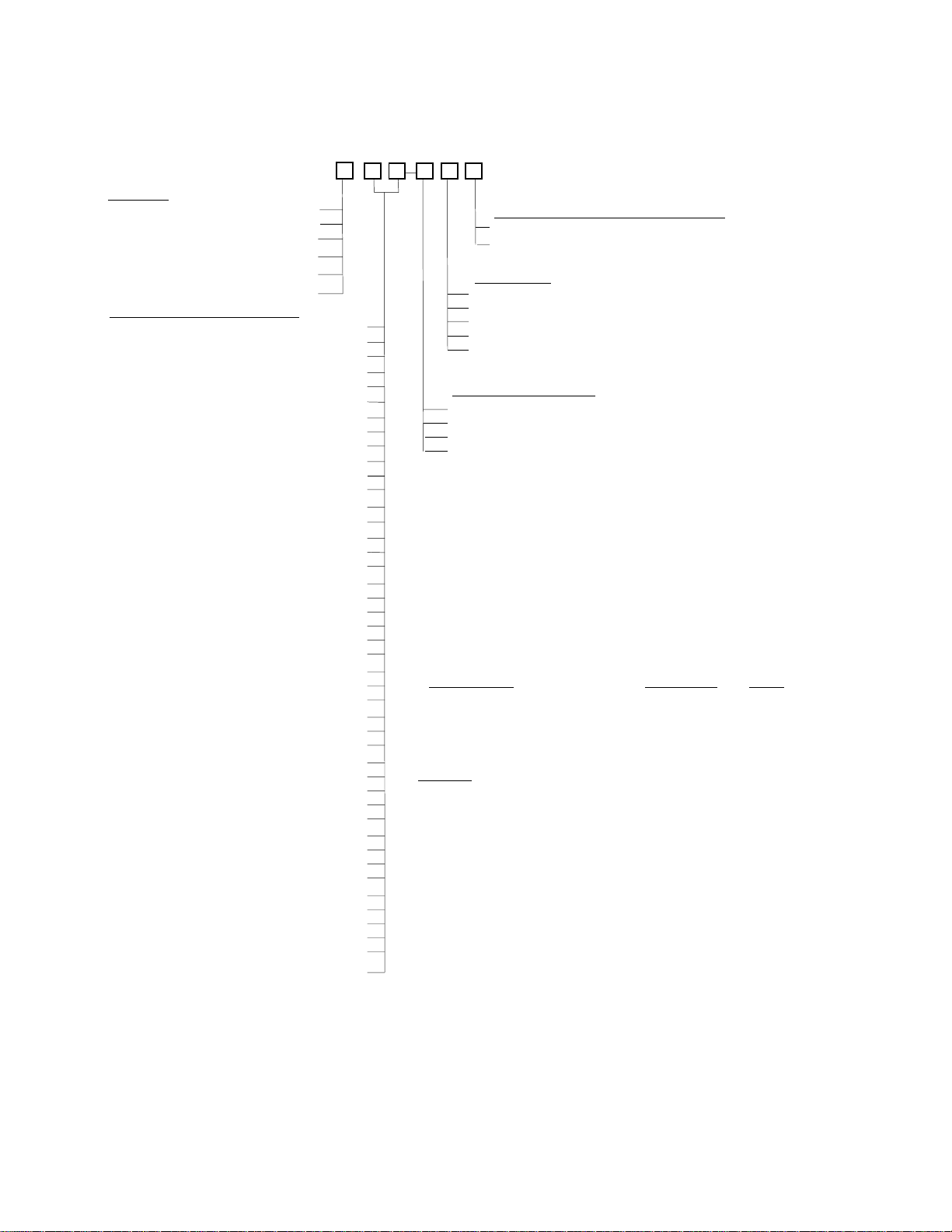
ORDERING INFORMATION FOR MODEL MBTR
02-03-06
Model: MB -
1 2 3 4 5 6
MODE (1)
T ............................ Transmitter Only
R .................................. Receiver Only
P ........................................... Repeater
S ......................... Transceiver SPI I/O
C ............Transceiver
9 .............................. Custom (Specify)
POWER & CASE ANTENNA (2)
0 0 ................................ 3V & Naked & Helical
0 1 ................................... 3V & Naked & Whip
0 2 ........................... 4-12V & Naked & Helical
0 3 ............................. 4-12V & Naked & Whip
0 4 ..................................... KEY-FOB "T" Only
0 5 ........................................ 3V & Plastic Case.
0 6 ................................... 4-12V & Plastic Case
0 7 ........................................... 3V & Metal Case
0 8 .....................................4-12V & Metal Case
0 9 .............................. Custom (Please Specify)
1 0 .................................. 3V & NEMA 4X Case
1 1 ............................ 4-12V & NEMA 4X Case
1 2 .................. Batt. Power & NEMA 4X Case
1 3 .......................... Isolated 5V & Plastic Case
1 4 ........................ Isolated 12V & Plastic Case
1 5 ........................ Isolated 24V & Plastic Case
1 6 ........................ Isolated 48V & Plastic Case
1 7 .......... Isolated 90-265VAC & Plastic Case
1 8 ............................Isolated 5V & Metal Case
2 0 ......................... Isolated 12V & Metal Case
2 1 ......................... Isolated 24V & Metal Case
2 2 ......................... Isolated 48V & Metal Case
2 3 ........... Isolated 90-265VAC & Metal Case
2 4 ................... Isolated 5V & NEMA 4X Case
2 5 ................. Isolated 12V & NEMA 4X Case
2 6 ................. Isolated 24V & NEMA 4X Case
2 7 ................. Isolated 48V & NEMA 4X Case
2 8 .. Isolated 90-265VAC & NEMA 4X Case
3 0 ...................................... 3V & Sanitary Case
3 1 ................................ 4-12V & Sanitary Case
3 2 ....................... Isolated 5V & Sanitary Case
3 3 ..................... Isolated 12V & Sanitary Case
3 4 ..................... Isolated 24V & Sanitary Case
3 5 ..................... Isolated 48V & Sanitary Case
3 6 ....... Isolated 90-265VAC & Sanitary Case
3 7 .................. Battery Power & Sanitary Case
3 8 ................................. 3V & Explosion Proof
4 0 ........................... 4-12V & Explosion Proof
4 1 .................. Isolated 5V & Explosion Proof
4 2 ................ Isolated 12V & Explosion Proof
4 3 ................ Isolated 24V & Explosion Proof
4 4 ................ Isolated 48V & Explosion Proof
45 . Isolated 90-265VAC & Explosion Proof
4 6 ............ Battery Power & Explosion Proof
µC UART I/O
CERTIFICATE OF COMPLIANCE (5)
0 ....................................................................... None
1 .................................................................. Included
OUTPUTS (4)
0 ............................................ None (For Transmitter)
1 ...................................................................... 3V Logic
2 .................... Open Collector Transmitter (O.C.T.)
3 ................................................ Relays N.O. Contacts
4 ............................................... Relays N.C. Contacts
FREQUENCY BAND (3)
0 ............................................................................. 315MHz
1 ............................................................................. 433MHz
2 ............................................................................. 868MHz
3 ............................................................................. 915MHz
NOTES: (Read Description Conditions & Specifications
Before Ordering)
1. "Transceiver µC" (Option C) UART can be disabled to accept Non-
UART Data.
2.1 Naked Mounts ertical on your P.C.B. For horizontal mount use Option
09 and specify horizontal mount.
2.2 Only the naked can be ordered with helical or whip, others only with
RPSMA connector and whip.
2.3 Up to 3 units can be fitted in Sanitary case with external power or 1
with battery power.
2.4 “KEY-FOB” only available with "Momentary" or "Latch" functions,
specify.
3. 868MHz (Option 2) not for U.S.A. Requires Affidavit, "T" & "R" must
have same band.
4. Transmitter has no outputs, use 0 option. Relays not available in
NAKED case, O.C.T. not available with "P", "S" or "C" modes. For
transceivers (S or C) and repeater (P) use 1 option.
5. See Note (*1) P. 5
6. Limited Lifetime Warranty
NOTES ON ACCESSORIES:
Battery Charger: P/N BC-48-4 (Charges Up To 4 Simultaneously) (8 Hrs.)
Extra Battery Pack: P/N BP-48-4 (4.8V @ 3A/Hr.)
Extra Batteries: P/N NMH-1.2-3 (12/V @ 3A/Hr.)
6
 Loading...