

OTE conn-x 585i, conn-x 585 Installation Instructions Manual

Installation Instructions
Wireless ADSL2+ Router
Thomson Gateway
585/585i v8 (4 Ethernet)

2-3 15x10 κλειστό 30x10 ανοιχτό
Led Indicators ............................................................................................................... 5
Contents
Package Contents ......................................................................................................... 4
PSTN Line ................................................................................................................. 8
ISDN Line ................................................................................................................. 11
Internet Configuration .................................................................................................. 14
Establish a Wireless Connection .................................................................................... 25
Enable/Disable Wireless Network & Reset Router .......................................................... 30
Online Security ............................................................................................................. 34
Connectors ................................................................................................................... 6
Access the Router Interface .......................................................................................... 29
Change User name
& Password for Internet Acess ......................................................... 31
Router Connection ........................................................................................................ 7
Minimum System Requirements
1. Pentium 4 Processor
2. Windows XP/Vista/7 or MAC OS 9.x
3. 1 GB memory RAM
4. 25 MB free hard disk space
5. Ethernet network card 10/100 Mbps
Οδηγίες εγκατάστασης
Ασύρματο ADSL2+ Router
Thomson Gateway
585/585i v8 (4 Ethernet)
4
PSTN/ISDN
PSTN ISDN
ISDN
4-5 15x10 κλειστό 30x10 ανοιχτό
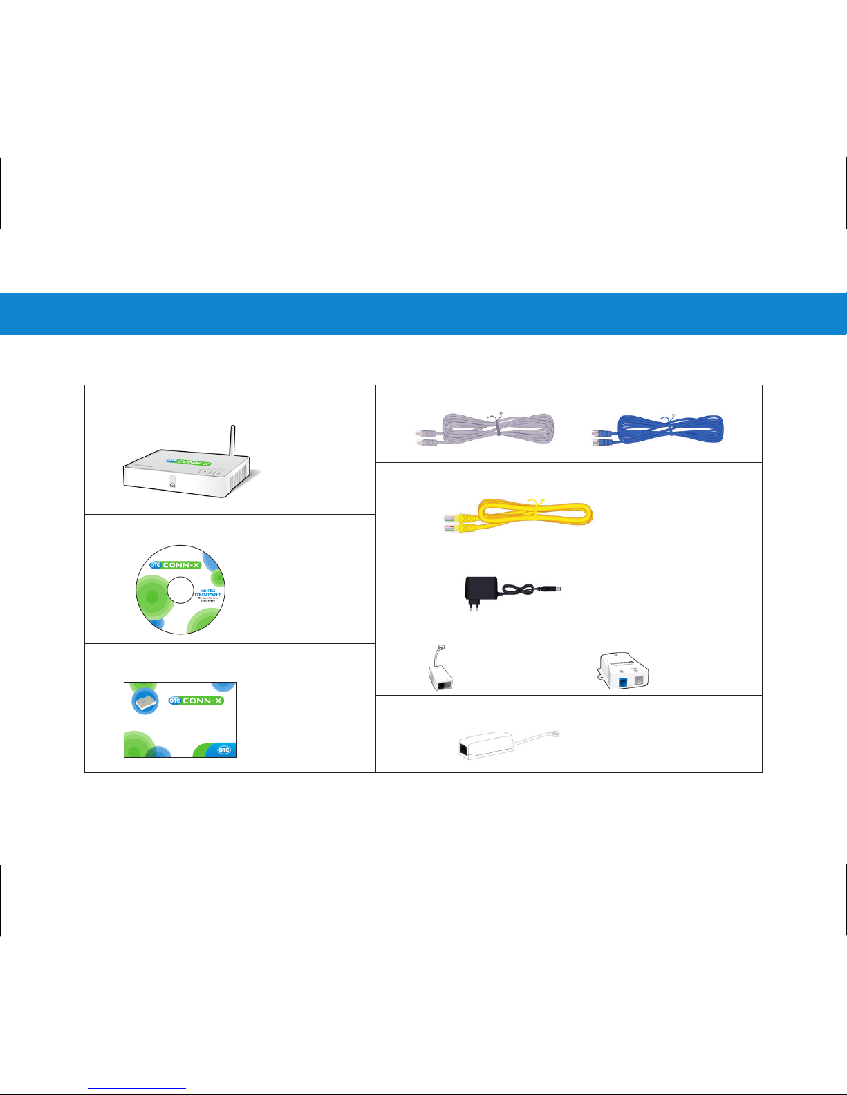
Package Contents
1 ADSL2+ Wireless Router
1 Ethernet Cable (RJ-45)
1 Power Supply Device
1 Splitter
1 Filter (for PSTN)
1 Installation CD
Installation Instructions
1 Telephone Cable (RJ-11) for PSTN or 2 for ISDN
5
INTERNET
WIRELESS
BROADBAND
POWER
ETHERNET
@
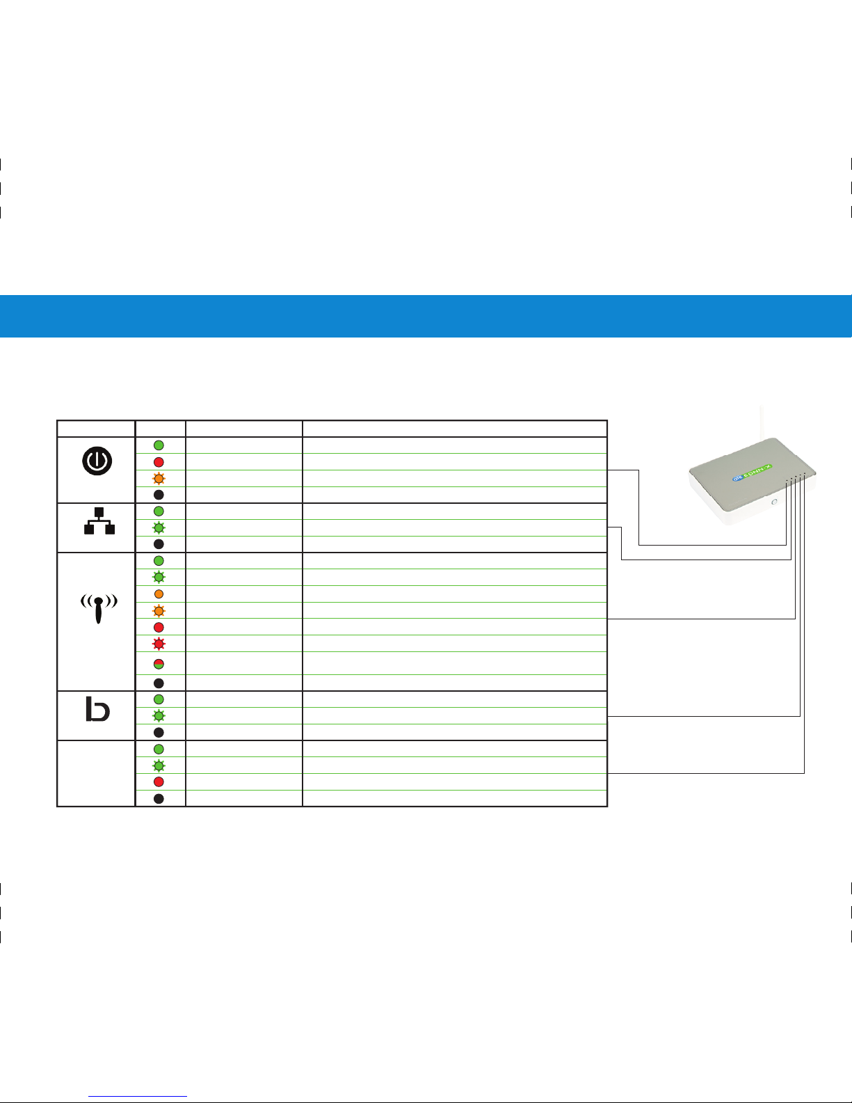
On the top panel of your ADSL2+ Router, you can find the following led
indicators. Please review below the description of each led (Picture 1).
Picture 1
State Description
(Red) Solid on
Power on, normal operation
(Orange) Blinking
Power on, self-test failed, device malfunction
Bootloader active (during upgrade)
Power off
(Green) Solid on
(Green) Solid on
(Green) Blinking
Ethernet connection, no activity
Ethernet activity
Off
Off
No Ethernet connection
(Green) Solid on
No wireless activity, WPA(2) encryption
(Green) Blinking
Wireless activity, WPA(2) encryption
(Orange) Solid on
No wireless activity, WEP encryption
(Orange) Blinking
Wireless activity, WEP encryption
(Red) Solid on
No wireless activity, no security
Wireless activity, no security
(Red/Green)
(Red) Blinking
Toggling
Wireless client registration phase
WLAN disabled
(Green) Solid on
DSL line synchronised
(Green) Blinking
Off
Off
Pending DSL line synchronisation
No DSL line
(Green) Solid on
Internet connectivity, no activity
(Green) Blinking
Internet activity
(Red) Solid on
Internet connection setup failed
Off
No Internet connection
Indicator Colour
Led Indicators
6
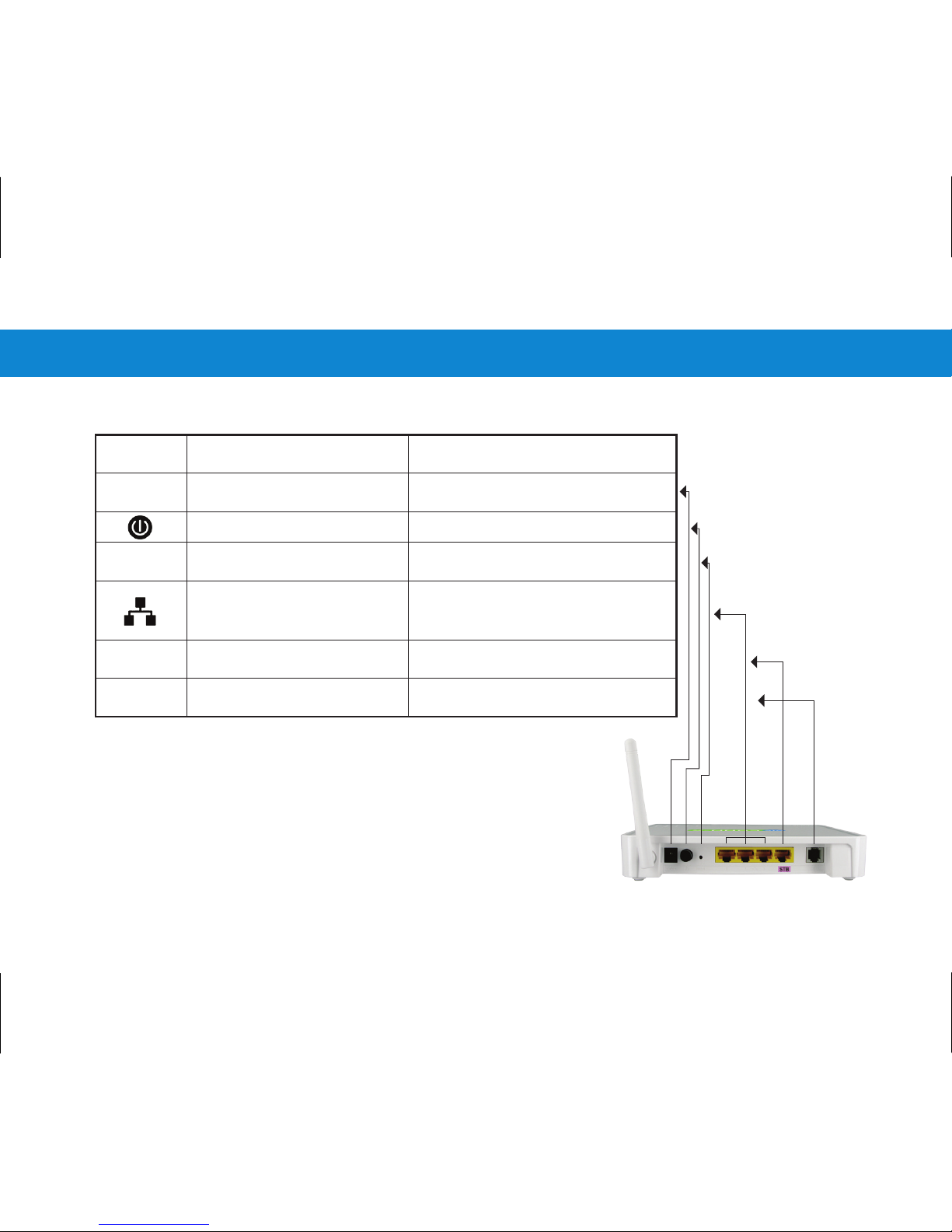
POWER
RESET
STB
DSL
6-7 15x10 κλειστό 30x10 ανοιχτό
Connectors
Power Button
Turns on/off the device
Reset Button
factory default settings
Resets your equipment to
Ethernet ports
for computer connection
Ethernet port
Used for connection to a 220V
power adaptor
local area network creation
computers for Internet access and
for Set-Top-Box (STB) connection
Provides connection to OTE's
television service through Internet
Port for telephone
cable connection (RJ-11)
Provides connection to the
telephone socket or the splitter
Picture 2
Power Supply
At the back of the Router there are
three
types of connectors (Picture 2).
INDICATION DESCRIPTION FUNCTION
Provide connection for up to 3

7
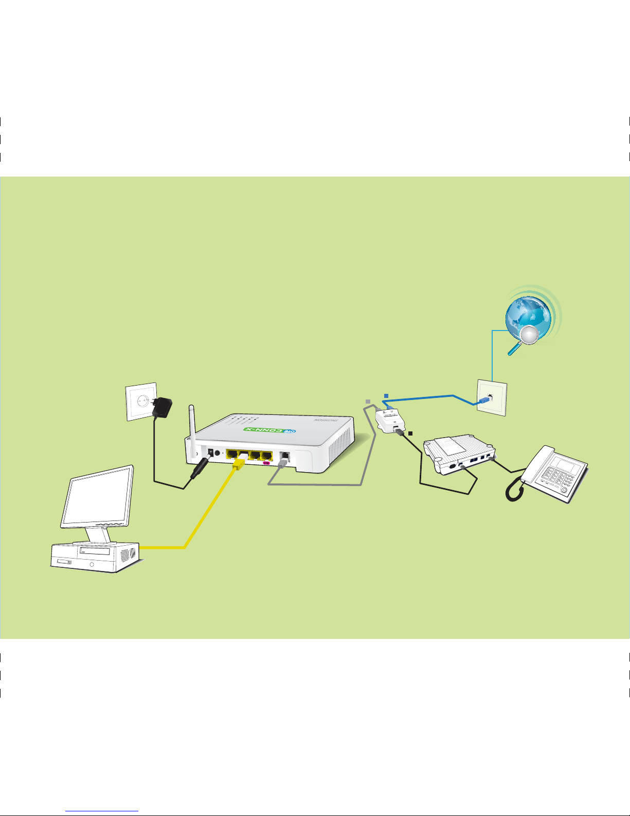
Connection & Settings
STEP 1
Router Connection
previous one.
Follow each STEP carefully and move on to the next only once you have completed the

8
8-9 15x10 κλειστό 30x10 ανοιχτό
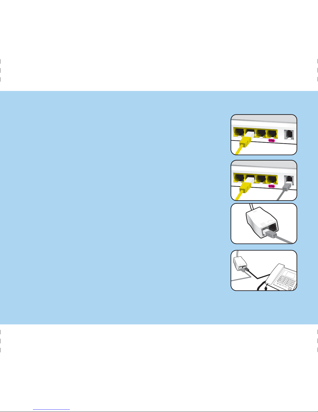
PSTN Line
Picture 3
Router as shown below (Picture 3).
If you have a PSTN telephone line (simple analog line), connect the
Α.
Β.
9
1
2
3
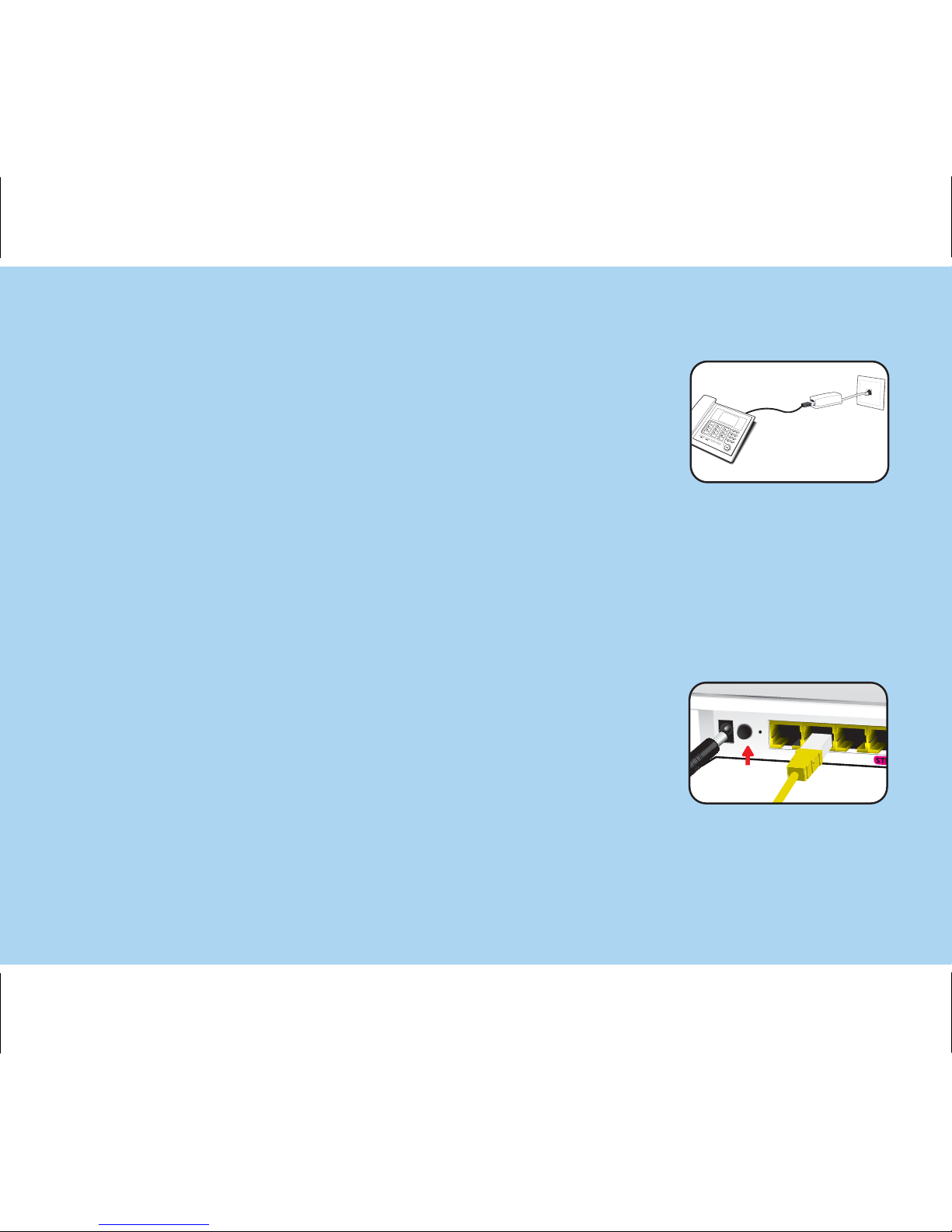
ADSL2+ Router.
A. Connect the grey RJ-11 telephone cable from
socket.
port of your computer to one of the 3 Ethernet ports of your
ATTENTION: The port with STB indication is used only
for a Set-Top-Box (STB) connection, which is
required for OTE's television service through Internet.
your ADSL2+ Router.
B. If you are using a telephone set in the same socket,
connect the splitter cable to your home telephone line
your home telephone line socket to the grey port of
Connect one end of the grey RJ-11 telephone cable
Connect one end of an RJ-11 telephone cable to the black
port of your splitter and the other end to your telephone
to the grey port of your ADSL2+ Router.
to the grey port of your splitter and the other end
set.
Connect the yellow Ethernet RJ-45 cable from the Ethernet
10
4
10-11 15x10 κλειστό 30x10 ανοιχτό
the house, you will need to place a filter between
the filter to the telephone line socket.
Note:
these sets and the telephone line socket.
Connect your telephone set to the filter and
If your telephone network is connected to any device
activity.
Please address a specialized installation crew for this
Connect the power supply device to the power connector
of your ADSL2+ Router, push the power switch of your
ADSL2+ Router to the ON position and wait for 2 minutes
before moving on to the next step.
If there are other telephone sets in other sockets inside
(alarm, call center, etc.), you should use an additional
ADSL filter or splitter.
11
ISDN Line
If you have an ISDN telephone line, connect the Router
as shown below (Picture 4).
Picture 4
 Loading...