

Page 1

802.11b Wireless Serial Port Adapter
WiSER2400.IP User Guide
www.otcwireless.com
Page 2

WiSER2400.IP
Wireless Serial Port Adapter
User Guide
Copyright
Information in this document is subject to change without notice. Complying with
all applicable copyright laws is the responsibility of the user. No part of this
document may be reproduced or transmitted in any form or by any means,
electronic or mechanical, for any purpose, without the express written permission
of the seller. If, however, your only means of access is electronic, permission to
print one copy is hereby granted.
The seller provides this documentation without warranty, term, or condition of any
kind. The seller may make improvements or changes in the product(s) and/or the
program(s) described in this documentation at any time.
Other product and company names herein may be trademarks of their respective
owners.
Copyright 2001-2003 OTC Wireless, Inc. All rights reserved.
Revision 1.08 May 14, 2003
ii
Page 3

TABLE OF CONTENT
CHAPTER 1 - INTRODUCTION
................................................................ 1
WISER2400.IP WIFI RADIO ................................................................................2
S
PECIFICATIONS ..................................................................................................2
CHAPTER 2 - INSTALLATION OF WISER2400.IP....................................... 3
INSTALLATION OF WISER2400.IP HARDWARE.......................................................3
Standard Hardware Items..............................................................................3
Power ............................................................................................................3
RS232 Connection.........................................................................................3
Status LED’s..................................................................................................4
I
NSTALLATION OF WISER2400.IP SOFTWARE .......................................................6
System Requirements ...................................................................................6
Installation......................................................................................................6
CHAPTER 3 - DIAGNOSTIC AND CONFIGURATION UTILITY
...................... 7
OVERVIEW ..........................................................................................................7
C
ONNECTION AND OVERALL STATUS PANEL ..........................................................8
R
ADIO STATUS PANEL..........................................................................................8
C
ONFIGURATION PANEL .......................................................................................9
RS232
S
ECURITY PANEL ...............................................................................................12
AND WLAN STATISTICS PANEL ...............................................................11
CHAPTER 4 - UDP/IP IMPLEMENTATION ............................................... 15
LEARNING THE DESTINATION MAC ADDRESS FROM ARP PACKETS. .......................15
O
UTGOING UDP/IP PACKET: ..............................................................................15
I
NCOMING UDP/IP PACKET:................................................................................16
CHAPTER 5 - TROUBLESHOOTING
...................................................... 17
BLANK PAGES APPEAR WHEN OPEN THE UTILITY PROGRAM ................................. 17
NO RADIO LINK..................................................................................................17
N
O DATA TRANSFER WHILE THE RADIO LINK IS GOOD ..........................................17
P
OOR LINK QUALITY ..........................................................................................18
R
ADIO INTERFERENCE........................................................................................18
T
ECHNICAL SUPPORT.........................................................................................19
APPENDIX A: LIMITED WARRANTY....................................................... 20
APPENDIX B: REGULATORY COMPLIANCE........................................... 21
GLOSSARY ........................................................................................ 23
iii
Page 4

Chapter 1 - INTRODUCTION
WiSER2400.IP is an 802.11b compliant, or WiFi, radio with an RS232 serial
interface.
The WiSER2400.IP radio takes serial data from the equipment or computing
device connected via its RS232 port, converts the serial data into 802.11compliant data packets, and transmits these packets with the RF modulation that
is compliant with the specifications of the 802.11b physical layer. On the
receiving end, the radio demodulates the RF signal, removes the Ethernet
(802.11) headers, unpacks the packet and delivers the data byte-by-byte to the
destination equipment/device through the RS232 serial port.
Each WiSER2400.IP radio acts as a “Station” and operates in either
infrastructure or ad-hoc mode in accordance to the 802.11 standards. As such,
this radios enables RS232-interfaced devices to participate in a wireless Ethernet
network. In this capacity, the radio, in addition to eliminating the RS232 cables,
functions as a media converter for RS232-interfaced equipment and computingdevices.
The radio is fully self-contained in performing the conversion between serial data
and wireless-Ethernet packets. That is, no device driver needs to be installed on
the hosting equipment or computing device the radio is connected to. True Plug
& Play feature therefore is achieved with any equipment or computing devices
with an RS232 port. This also means the radio can be used on equipment and /or
computing-devices with any Operating Systems. This is particularly useful for
instruments/equipment where the use of RS232 interface is utilized. Examples
include cash registers, electronic whiteboards and navigation instruments.
WiSER2400 has a compact form-factor that blends easily into an office/
classroom environment. It also lends particularly well to portable applications.
The specifications are given on the next page.
The utility program can be used to monitor the communication condition once the
radio is in operation. The radio runs self-sufficiently without the aid of any driver
program in the host equipment or computer connected to the radio. This utility
program therefore is intended to be, in most cases, just a tool for the network
operators. The utility is also needed to configure the WiSER2400.IP for both
wireless and UDP/IP parameters. The utility program is simple to install and
easy to use through its graphic user interface. The details are described in
Chapter 3.
Note: The terms WiSER2400 and WiSER2400.IP are used interchangeably
through out this document
1
Page 5

WiSER2400.IP WiFi Radio
Key Features
Plug & Play operation—
o No driver on the host device is required for radio operation
o Radio operation is independent of the operating system on the host equipment or device
(Windows 98/NT/2000/ME/XP, Linux, Unix, embedded, etc.), as long as an RS232 port is
properly supported
Supports 64-bit and 128-bit encryption for secured communication
Industry standard IEEE 802.11b-compliant wireless interface
11Mbps data rate and automatic selection of lower data rate (5.5, 2 and 1 Mbps) in degraded RF
environment
Integrated omni-directional-antenna to provide best tradeoff between link-quality and mobility
Microsoft-Windows-based configuration utility
Standard-compliant wireless networking for computers and equipment with an RS232 interface
Embedded devices, tools, instruments, equipment and appliances that can benefit from the re-
configurability of wireless link yet are unfriendly to the installation of device-drivers
o
POS equipment for stores where re-configuration is frequent
o Control/monitor equipment where mobility is required
Applications
Specifications
Model
Standard
Host Interface
Frequency
RF Channels
Transmission power
Receiver sensitivity
Antenna
Data Rate
Modulation
Link Distance
Network Types
Data Encryption
Network Security
AC adapter
Current consumption
LED Indicators
Operating
Temperature
Regulation
Compliance
WiSER2400.IP
802.11 and 802.11b
RS232
2.4GHz – 2.495GHz
11 channels (US, Canada), 13 channels (Europe), 14 channels
(Japan)
14dBm at antenna input typical
-80dBm @1e-5 BER typical
Integrated dipole antenna with ~2dBi gain
11, 5.5, 2 or 1 Mbps fixed rate, or configured to automatic rate
selection
CCK, Direct Sequence Spread Spectrum
~1200 ft in open space
Support normal station to AP link in the infrastructure mode
Support the standard 64-bit and the 128-bit WEP
MAC-address-based access control
Output: 5V, 1A; Input: 100-120V, 50-60Hz, ~0.3A
<480mA (max. reached in transmit-mode)
4: Power, Transmission, Receiving, Link
-10°C – 50°C
FCC part 15,Class B
CE ( ETSI EN 300 328-1, ETSI EN 301 489-17)
IC (for Ubicom-based model)
2
Page 6

Chapter 2 - INSTALLATION OF WiSER2400.IP
Installation of WiSER2400.IP Hardware
Standard Hardware Items
1 WiSER2400.IP radio
1 3-foot RS232 –P cable
1 ac-dc power adapter
1 pair of Velcro mounting pads
Power
This radio connected to your equipment draws power from the provided AC-DC
power adapter that plugs into a wall outlet.
RS232 Connection
The WiSER2400.IP radio is shipped with one RS232 cable. This 3-foot cable is
intended for use with any RS232 equipment (whiteboard, instrument, etc.) and
has the specification listed below:
Option –P—terminates in a male DB-9 connector, no dc-power is available
from this cable
Connect the modular plug (which resembles an over-sized telephone plug) of the
RS232 cable to the modular jack (which resembles an over-sized telephone jack)
at the bottom panel of the WiSER2400 radio. Connect the DB-9 (9-pin, can be
female or male depending on the equipment) connector of the RS232 cable to
the RS232 port in the client equipment or computer.
3
Page 7
Status LED’s
A
Power on the WiSER2400 Radio, the LED’s on the front panel should exhibit the
following patterns:
LED Color Light Blinking Pattern Indication
ON RED Steady on Proper power is supplied
Steady on Unit linked to any wireless station RX GREEN
Steady blink Unit not linked to any unit
TX RED Flickering Unit transmitting RF signal
LINK YELLOW Steady on
Not in use
The WiSER2400.IP radio is configured as a client Station and cannot be
changed. As a station, one of the most useful diagnostic tools may be the green
RX LED: a blinking green RX LED indicates the absence of a useful
communication link.
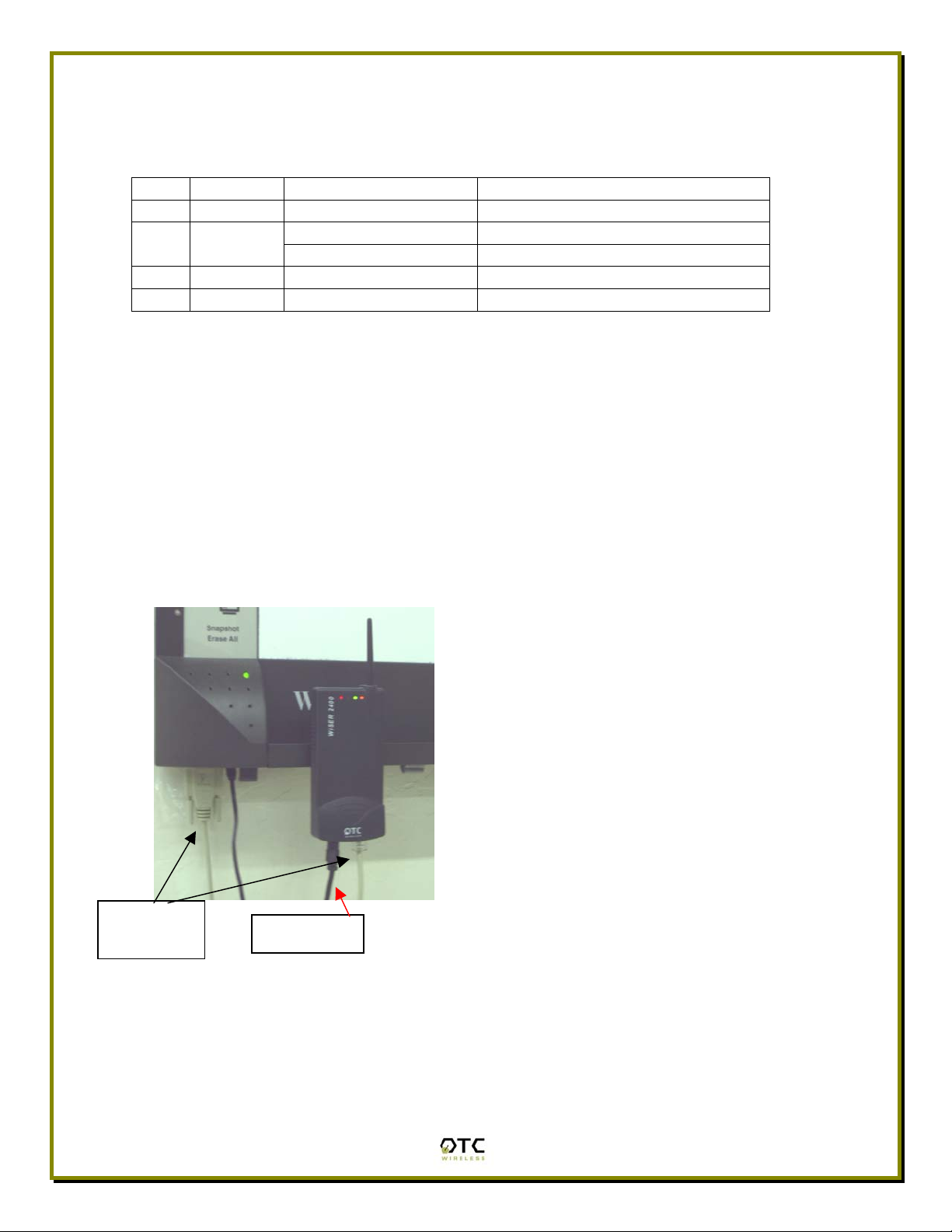
Once the hardware is checked out to work properly with the intended host device
or equipment, the radio can be secured in the desire location by the pair of
Velcro pads supplied.
3-foot –P
RS232 Cable
n installation example where the
WiSER2400.IP is connected to an RS232
equipment (whiteboard)
Radio Power
4
Page 8

5
Page 9

Installation of WiSER2400.IP Software
System Requirements
For using the WiSER2400.IP Wireless Ethernet Adapter’s utilities software, your
computer must meet the following minimum requirements:
Windows® 95 (OSR2)/ 98 (SE)/NT/ME/2000/XP
One COM port (with a DB-9 male connector or an appropriate adapter to
connect to a DB-9 female connector)
Installation
To install the utility program, simply insert the CD-ROM provided. Copy the
“wue101.exe” file to the desired location on your PC.
Note that to use the WiSER2400.IP properly as intended, you must configure the
WiSER2400.IP radio to the appropriate IP [Internet Protocol] configurations as
your network.
Note: For the utility program to configure or monitor the WiSER2400 radio
through a COM port, there must be no another serial (RS232) program
that also accesses or control the same COM port.
6
Page 10

Chapter 3 - Diagnostic and Configuration Utility
Overview
This chapter describes the functionalities and operations of WiSER2400.IP
Diagnostic and Configuration Utility program. The utility program can be used to
configure and monitor WiSER2400.IP radios. The WiSER2400.IP utility program
is supported on Microsoft Windows® 95(OSR2), 98(SE), NT, Millennium, 2000,
and XP. Figure 1 below is WiSER2400.IP utility main window.
Warning: The utility program may not work simultaneously with another RS232
application program since both programs would compete for the control to the
same RS232 serial (COM) port connecting the WiSER2400 radio.
Figure 1. Main Window of WiSER2400.IP Utility Program
7
Page 11

In general, the main window consists of five panels: Connection and Overall
Status, Radio Status, Configuration, Security, and RS232 and WLAN Statistics.
Connection and Overall Status Panel
The Connection and Overall Status panel, shown in figure 2, controls and
maintains the serial connection, and displays up-to-date connection status. It has
a pull down menu for choosing COM ports, a Connect button, and a text field
displaying connection status.
Figure 2. Connection and Overall Status Panel
The pull-down menu allows users to select COM ports (RS232 serial port) so that
the utility program knows where to connect to WiSER2400 radio unit. The pulldown menu becomes inactive and inaccessible when the connection between
the WiSER2400 radio and the utility program is active.
After appropriate COM port is selected from the pull-down menu, click Connect
button to have the utility program claim the COM port. If a COM port is
successfully claimed by the utility, the Disconnect will be displayed on the
button instead of Connect. Click Disconnect button to release the control of the
COM port from the utility program.
Note: Other panels in the main window stay inactive unless a COM port is
claimed by the utility program.
The status text field displays connection status and the utility command
information between WiSER2400 utility program and the radio unit.
Radio Status Panel
The Radio Status Panel has only one mode, STA mode, shown in figure 3.
8
Page 12

Figure 3. Radio Status Panels (AP: left; Station: right)
In general, the Radio Status Panel displays the firmware version, firmware
release date, role, and communication channel used by the radio. The panel
displays additional radio signal information such as the Port Status, Link Quality,
and Signal strength.
Configuration Panel
This panel contains the following fields: SSID, Network Type, Baud rate,
Channel, Max Bytes/Pkt, End Frame Byte of this unit. MAC addresses, IP
addresses and UDP ports of this unit and the destination unit are also in this
panel. To retrieve the settings, click on Refresh button on the main panel.
Figure 4. Configuration Panel
9
Page 13

In addition, there are two buttons on this panel. The “Default Setting…” button is
to set the Max Bytes/Pkt and End Frame Byte to 6 bytes per packet and 0x0D
(Carriage Return) respectively.
The “Apply” button on this panel is for sending the ‘Config’ command to the radio
unit that sets its configuration with above fields.
Followings are the detail descriptions of the fields:
SSID: The SSID that this radio would connect to. 32 characters maximum. An
empty entry is acceptable but note that the radio would interpret it as ‘ANY’ which
is a special SSID. A station with this special SSID would try to join a wireless
network regardless of its SSID.
Network Type: this is the 802.11b mode the radio unit is running on. It can be
either”Ad hoc” or “Infrastructure”. For WiSER2400.IP to connect with a normal
AP, always select “Infrastructure” mode Please refer to IEEE 801.11
documentation for more information of the Network Type. Default value:
Infrastructure.
Baud rate: user-configurable. This is the baud rate the radio unit will use to
transmit and receive RS232 data. Supported values: 2400, 4800, 9600, 14400,
19200, 38400, 57600, and 115200 bps. Default value: 9600 bps.
Channel: this field is applied only when the radio unit functions in ‘Ad hoc’ mode.
Therefore, it is hid when the radio unit functions in ‘Infrastructure’ mode.
Supported values: 1 – 14 channels.
Max Bytes/Pkt: This value specifies the maximum number of bytes a UDP
packet can contain. Range: 1 to 200. Default value: 6.
End Frame Byte: This value specifies a special character that signals the end of
a command (or portion of data) and the command (or portion of data) should be
sent to the destination unit right after the radio receives this special character.
Range 0x00 to 0x1F. Default value: 0x0D = Carriage Return. Note that user can
choose ‘None’ value which means he would not use any special character in any
case.
MAC Addr (MAC address of this unit): the MAC address of this radio.
MAC Addr (MAC address of destination unit): the MAC address of the
destination device. The radio unit learns the MAC address of the destination unit
from ARP response packets sent from the device with associated IP address.
IP Addr (IP address of this unit): the IP address of this radio. Configurable.
IP Addr (IP address of destination unit): the configurable IP address of the
device which this radio would communicate with.
UDP Port (of this unit): the port number that this radio uses to communicate.
This port number is the source Port in UDP packets sent from this radio. Fixed
value: 8002
UDP Port (of destination unit): the port number the destination device listens on
to get the UDP packet. This port number should be the destination Port on UDP
packets destined to this radio.
10
Page 14

RS232 and WLAN Statistics Panel
The transmission statistics of the RS232 (COM port) and Wireless Local Area
Network (WLAN) is shown in this panel. To retrieve the statistics, click Refresh
button located at the bottom of the main window of the utility program. The
following explains the statistics shown in the panel:
1. RS232 Statistics:
a. COM Sent: This number is the total bytes that the Unit sends
through the connected COM port.
b. COM Received: This number is the total bytes that the Unit
received through connected COM port. This value is the sum of the
following values:
i. Without error: Total bytes received without error.
ii. Break Detect error: Total bytes received as break detect
error.
iii. Frames error: Total bytes received with frame error.
iv. Overrun error: Total bytes received with overrun error.
c. Frames Discard: This number is the total number of frames that
were discarded while the firmware tried to en-queue them to WLAN
queue (send to MAC). Lacking of memory is the main reason for a
frame to be discarded.
2. WLAN Statistics:
a. Transmitted Frames: This number is the total UniCastFrames and
MultiCastFrames that the MAC successfully transmitted
b. Transmitted Retried Frames: This number is the total
SingleRetryFrames and MultiRetryFrames that the MAC
transmitted.
c. Transmitted Octets: This number is the total bytes that the MAC
successfully transmitted (UnicastOctets and MulticastOctets)
d. Received Frames: This number is the total UniCastFrames and
MultiCastFrames that the MAC successfully received.
e. Received Error Frames: This number is the total frames that the
MAC received with the following errors: DiscardNoBuffer,
DiscardsWrongSA, DiscardWepUndecryptable, and Frame-CheckSequence Errors.
f. Received Octets: This number is the total bytes that the MAC
successfully received (UnicastOctets and MulticastOctets)
11
Page 15

Security Panel
This panel shown in Figure 5 enables users to configure security options for the
WiSER2400 radios. WiSER2400 supports Wired Equivalent Privacy (WEP)
encryption both 64bits and 128bits.The Security panel contains two sub-panels,
Encryption sub-panel and WEP Keys Creation sub-panel.
Figure 5 Security Panel
Encryption sub-panel
This sub-panel allows user to adjust the security level as needed. There are
three radio buttons to select the encryption levels, and only one radio button can
be selected at a time. The function of each radio button is described below:
a. Disable: if checked, the WEP is turned off and WEP Keys Creation sub-
panel becomes inactive.
b. 64-bits: if checked, the WEP is turned on using 64-bit encryption and
WEP Keys Creation sub-panel becomes active.
c. 128-bits: if checked, the WEP is turned on using 128-bit encryption and
WEP Keys Creation sub-panel becomes active.
Before applying the WEP 64 or 128-bit encryption to the radios, the user must
complete the key settings in WEP Keys Creation sub-panel first.
WEP Keys Creation Sub-panel
This sub-panel allows user to generate users’ own WEP encryption keys and can
be made active only when either 64 bits or 128 bits radio button in the Encryption
sub-panel is selected.
12
Page 16

There are two methods to generate WEP encryption keys. One is to use auto key
generation through the Passphrase field, and the other method is to manually
input a set of keys in the Manual Entry fields.
To auto-generate WEP encryption keys, select the radio button next to the
Passphrase label and then the users can enter up to any 64 characters in the
Passphrase field. Click the Apply button to apply the encryption key setting.
Notice that when this method is selected the Manual Entry fields are “grayed out”
to disallow manual entries of WEP keys.
Figure 6 Create WEP Keys with Passphrase
To manually input keys, select the radio button next to the Manual Entry and then
enter hexadecimal numbers to the fields next to Key 1 to Key 4. Click the Apply
button to apply the encryption key setting. Notice that when this method is
selected the Passphrase field is “grayed out” to disallow any input to the
passphrase field.
FIGURE 7 CREATE WEP KEYS WITH MANUAL ENTRIES
13
Page 17

The Manual Entry Key 1/2/3/4 fields accept hexadecimal inputs as the encryption
keys. If 64 bits encryption is enabled, each key field allows the user to enter up to
10 hexadecimal characters. If 128 bits encryption is enabled, each of the key
field allows up to 26 hexadecimal characters.
he remaining fields in the Security Panel are described below.
T
a. Deny Unencrypted Data Frames: if checked, the firmware will block
unencrypted data frames from being received.
b.
Transmission key: This allows user to choose from key 1 to key 4 for
transmission. The default key is set to Key 1.
c. oose how many frames the
WEP key factor: this list box allows user to ch
Initialize Vector (IV) is reused. It contains four options: every frame, every
10 frames, every 50 frames, and every 100 frames. The default key factor
is Every 100 frames.
When the Apply button is pressed, the program validates all entered data and
prompts the user to re-enter the data if any of the input data is invalid. If all data
is valid, the entered data will be applied to the radio unit. When the Cancel
button is clicked, all entered data under Security Panel is discarded.
14
Page 18

Chapter 4 - UDP/IP Implementation
This section describes how the radio firmware composes RS232 data into UDP
packets and sends them out, as well as how it receives the UDP packets and
performs necessary checks. If all checks are passed, it retrieves the RS232 data
from the packets, and sends the data out to RS232 cable.
When composing the UDP/IP packet header, the firmware only sets the
important fields in the packet header, other less important fields are set with
correct, fixed values and these values are unchanged during the operation time
of the radio.
Upon receiving UDP/IP packets, the firmware only checks for validity of some
important fields in the packet header. Others may be ignored.
Learning the destination MAC address from ARP packets.
After powered-up or its configuration is reset by the utility, the radio needs to
learn the MAC address associated with the IP address of the destination device.
It does this by composing an ARP packet and sends it out every second until it
receives an ARP response from the intended device. This radio unit will not send
and receive any thing until it receives the correct ARP response.
This part is very critical. So, if the radio seems not to communicate, please
check the correctness of the “Dest unit’s IP address” using the utility.
Outgoing UDP/IP packet:
a. IP Header:
i. Version: 4. (Fixed)
ii. Header length: 5 (Fixed)
iii. TOS: 8 (Fixed)
iv. Total length = IP header length + UDP header length + serial data length
v. ID = some timing value. Not important.
vi. Flags and fragment offset = 0x4000. (Don’t fragment, Last fragment,
fragment offset is 0)
vii. TTL: 128 (Fixed)
viii. Protocol: UDP (Fixed)
ix. IP Header check sum = this IP header’s checksum.
x. Source IP address = “IP Addr” in the “This Unit” portion in the
configuration panel.
xi. Destination IP address = “IP Addr” in the “Dest. Unit” portion in the
configuration panel.
xii. No option.
15
Page 19

b. UDP header:
i. Source Port number = “UDP Port” in the “This Unit” portion in the
configuration panel.
ii. Destination Port number = “UDP Port” in the “Dest. Unit” portion in the
configuration panel.
iii. UDP Length = UDP header length + data length. This data length would
be =< “Max Bytes/Pkt” value.
iv. The “Max Bytes/Pkt” field is in the “Configuration Panel.” (See section II
for detail).
v. UDP Check sum = calculated over UDP header and serial data.
c. RS232 Data: this is the serial data received from serial port.
Incoming UDP/IP packet:
a. IP Header: checking on the following fields. Other fields that are not
mentioned are not checked.
i. Total length: must be greater than IP header length and UDP header
length
ii. Flags and Fragment offset: must be “Don’t fragment” and “Last fragment”
iii. Protocol: must be UDP.
iv. IP Header check sum: must be correct
v. Source IP address: must be equal “IP Addr” in the “Dest. Unit” portion in
the configuration panel.
vi. Destination IP address: must be equal “IP Addr” in the “This Unit” portion
in the configuration panel.
b. UDP header: checking on the following fields. Other fields that are not
mentioned are not checked.
i. Source Port number: must be equal “UDP Port” in the “Dest. Unit” portion
in the configuration panel.
ii. Destination Port number: must be equal “UDP Port” in the “This Unit” in
the configuration panel.
iii. UDP Length = UDP header length + data length. The data length has to
be =< 200.
iv. UDP Check sum: ignored if 0. Otherwise, a checksum calculation is
performed on UDP header and serial data.
16
Page 20

Chapter 5 - Troubleshooting
Blank Pages Appear When Open the Utility Program
It is possibly due to the unavailability of the COM port. Please pay attention to the
Connection and Overall Status field next to the Connect button. Press the
Connect button again to see if the status indicates “Connected.” If not, check to
see if you have another running program that access the same COM port.
No Radio Link
If the Link Quality indicator in the Radio Status panel shows 0%, check the
following for possible causes:
• Make sure that the Signal Strength indicator under Radio Status panel is
not zero. A minimum of 20% is recommended. If the “Signal Strength” is
less than 20%, the distance between the WiSER2400 and the targeted AP
may be too far. Decrease the distance between the radio pair to see if the
radio link can be improved.
• Make sure that the encryption keys are entered correctly if WEP
encryption is enabled.
• Make sure that there is no RF interference present in the radio network.
No Data Transfer While the Radio Link is Good
If the Link Quality indicator shows good link quality, but the host
computer/equipment cannot properly exchange data:
• Make sure the RS232 cable are properly connected to the radio and
computer/equipment.
• Make sure that the RS232 cable in use are not defective.
• Make sure that the COM port on the computer/equipment is available, not
used by another active program/process.
17
Page 21

Poor Link Quality
If the Signal Strength indicator is reasonably high (>20%) and the Link Quality is
not zero, but the “Link Quality” stays in the Poor range, it could be due to one of
the following reasons:
• Make sure that radio interference is not present in the radio network.
• Make sure that the radio is not surrounded by many strongly reflecting
(metallic) surfaces. With multiple reflecting surfaces between the radio in
question and the target radio, a severe multi-path problem may introduce
high bit error rate despite a strong Signal Strength.
• Make sure that there is no severe packet collision caused by a “hidden
node” problem. A “hidden node” problem is the situation where the RF
signal from two or more Station radios cannot reach each other (but can
reach the AP). In such situation, multiple Stations may attempt to transmit
data packet to the AP at the same time and therefore cause packet
collision. To solve this problem, re-arrange the Stations in question such
that the RF signals are mutually sensible by all Stations. There is no
guarantee that the packet collision can be entirely eliminated, but the
severity can be reduced enough to see visible improvement of the link
quality.
Radio Interference You may be able to minimize RF interference by doing the following:
• Although WiSER2400, when properly configured, seeks a clear channel to
use, it cannot avoid interference if too many 2.4GHz interference sources
are present. A “clear” channel should be at least 20MHz, but preferably
30MHz, apart from any other channel in use. Find out other usages in this
frequency band in the vicinity and try to coordinate the channel
assignment with other users.
• Reseat the WiSER2400 radio to a location where the interference is
minimized; in general, increasing the distance between the radio pair may
cause radio interference.
• Avoid using 2.4GHz cordless phone in the vicinity of the radios
• Keep the computer with the WiSER2400 radio away from the microwave
oven and large metal objects.
• Consult the dealer or an experienced radio technician for help and
assistance.
18
Page 22

Technical Support
If problems are still not solved, please contact our Technical Support to obtain
further assistance.
Call: 1-800-770-6698 in USA
Call: 011-510-490-8288 outside of USA
E-mail:techsupport@otcwireless.com
19
Page 23

Appendix A: Limited Warranty
WiSER2400 Hardware
The seller warrants to the end user (“Customer”) that this hardware product will
be free from defects in workmanship and materials, under normal use and
service, for one (1) year from the date of purchase from the seller or its
authorized reseller. The seller’s sole obligation under this express warranty shall
be, at the seller’s option and expense, to repair the defective product or part,
deliver to Customer an equivalent product or part to replace the defective item, or
if neither of the two foregoing options is reasonably available, The seller may, in
its sole discretion, refund to the Customer the purchase price paid for the
defective product.
All products that are replaced will become the property of the seller.
Replacement products may be new or reconditioned.
WiSER2400 Software
The seller warrants to Customer that each software program licensed from it,
except as noted below, will perform in substantial conformance to its program
specifications, for a period of one (1) year from the date of purchase from the
seller or its authorized reseller. The seller warrants the media containing
software against failure during the warranty period. No updates are provided. The
seller’s sole obligation under this express warranty shall be, at the seller’s option
and expense, to refund the purchase price paid by Customer for any defective
software product, or to replace any defective media with software which
substantially conforms to applicable seller published specifications. Customer
assumes responsibility for the selection of the appropriate application programs
and associated reference materials. The seller makes no warranty or
representation that its software products will meet Customer’s requirements or
work in combination with any hardware or software applications products
provided by third parties, that the operation of the software products will be
uninterrupted or error free, or that all defects in the software products will be
corrected. For any third party products listed in the seller software product
documentation or specifications as being compatible, the seller will make
reasonable efforts to provide compatibility, except where the non-compatibility is
caused by a defect in the third party’s product or from use of the software product
not in accordance with the seller’s published specifications or user manual.
20
Page 24

Appendix B: Regulatory Compliance
FCC Part 15 Declaration of Conformity (DoC)
The equipment is confirmed to comply with the requirements of FCC Part 15
rules. The operation is subject to the following two conditions:
1. This device may not cause harmful interference, and
2. This device must accept any interference received, including interference
that may cause undesired operation.
FCC ID: MKZ0207232XG
FCC Rules and Regulations - Part 15
Warning: This device has been tested and found to comply with the limits for a
Class B digital device pursuant to Part 15 of the Federal Communications
Commissions Rules and Regulations. These limits are designed to provide
reasonable protection against harmful interference when the equipment is
operated in a commercial environment. This equipment generates, uses, and can
radiate radio frequency energy and, if not installed and used in accordance with
the instruction manual, may cause harmful interference to radio communications.
However, there is no guarantee that interference will not occur in a particular
installation. If this equipment does cause harmful interference to radio or
television reception, which can be determined by turning the equipment off and
on, the user is encouraged to try and correct the interference by one or more of
the following measures:
. Relocate your WLAN equipped laptop computer.
. Increase the separation between the WLAN equipped laptop computer and
other electronics.
. Connect the WLAN equipped laptop computer into an outlet on a circuit
different from that of other electronics.
. Consult the dealer or an experienced radio/TV technician for help.
Caution: Changes or modifications not expressly approved by OTC Wireless
could void the user’s authority to operate the equipment.
FCC Radiation Exposure Statement
This equipment complies with FCC radiation exposure limits set forth for an
uncontrolled environment. This equipment should be installed and operated with
minimum distance of 20cm between the radiator & your body. This transmitter
must not be co-located or operating in conjunction with any other antenna or
transmitter.
21
Page 25

European Community (EC) Directives Conformity and Restrictions
This product is in conformity with the protection requirements of EC Council
directives 89/336/EEC, 73/23/EEC, and 1999/5/EC on the approximation and
harmonization of the laws of the Member States relating to electromagnetic
compatibility, safety of electrical equipment designed for use within certain
voltage limits and on radio equipment and telecommunications terminal
equipment.
Compliance is indicated by the CE marking
This product satisfies the radio spectrum requirements of EN 300 328-1, the
EMC requirements of EN 301 489-17 and the safety requirements of EN 60950.
22
Page 26

Glossary
Access Point An internetworking device that seamlessly connects wired and wireless networks.
Access Points combined with a distributed system support the creation of multiple radio cells that
enable roaming throughout a facility.
Ad Hoc Network A network composed solely of stations within mutual communication range of
each other (no Access Point connected). The Ad Hoc network offers peer-to-peer connections
between workstations, allowing communication between computers within range that have an
802.11
DSSS compatible PC card installed.
Channel A medium used to pass data units that can be used simultaneously in the same volume
of space by other channels of the same physical layer, with an acceptably low frame error ratio
due to the absence of mutual interference.
Encapsulated An Ethernet address mode that treats the entire Ethernet packet as a whole and
places it inside an 802.11 frame along with a new header.
Ethernet The most widely used medium access method, which is defined by the IEEE 802.3
standard. Ethernet is normally a shared media LAN; i.e., all the devices on the network segment
share the total bandwidth. Ethernet networks operate at 10Mbps/100Mbps using CSMA/CD to run
over 10BaseT/100BaseT cables.
IEEE 802.11 The IEEE 802.xx is a set of specifications for LANs from the Institute of Electrical
and Electronic Engineers (IEEE). Most wired networks conform to 802.3, the specification for
CSMA/CD-based Ethernet networks or 802.5, the specification for token ring networks. 802.11
defines the standard for wireless LANs encompassing three incompatible (non-interoperable)
technologies: Frequency Hopping Spread Spectrum (FHSS), Direct Sequence Spread Spectrum
(DSSS), and Infrared. IEEE standards ensure interoperability between systems of the same type.
Infrastructure Network A wireless network centered about an Access Point. In this environment,
the Access Point not only provides communication with the wired network but also mediates
wireless network traffic in the immediate neighborhood.
IP Internet Protocol. The standard protocol within TCP/IP that defines the basic unit of information
passed across an Internet connection by breaking down data messages into packets, routing and
transporting the packets over network connections, then reassembling the packets at their
destination. IP corresponds to the network layer in the ISO/OSI model.
LAN Local Area Network. A communication network that serves users within a defined
geographical area. The benefits include the sharing of Internet access, files, and equipment, such
as printers and storage devices. Special network cabling (10BaseT) is often used to connect the
PCs together.
RS232 An EIA standard for serial data communication between equipment and computing
devices.
SSID Service Set ID. A group name shared by every member of a wireless network.
Station The Station is the component that connects a host computer or device to the wireless
medium. It may be referred to as the Wireless Network Adapter or the Wireless Network Interface
Card.
WEP Wired Equivalent Privacy. The optional cryptographic confidentiality algorithm specified by
802.11 used to provide data confidentiality that is subjectively equivalent to the confidentiality of a
wired LAN medium that does not employ cryptographic techniques to enhance privacy.
23
 Loading...