

Page 1
Included with AVCW 100/200, 109/209 , 115 /215:
! AVCW Radio Unit
! DC Injector
! 9V AC Adapter
! White 3 ft Straight-thru UTP Cat5 Cable
! Blue 7 ft Crossover UTP Cat5 Cable
! Black 3 0 ft UTP Cat5 Cable
! Installation CD with Utilities and Manuals
! Mounting Bar
! Hose Clamp
! AVCW Quickstart Guide
Step 1: Connect the AVCW-100/109/115
Virtual Cable Wi-Fi Access Point
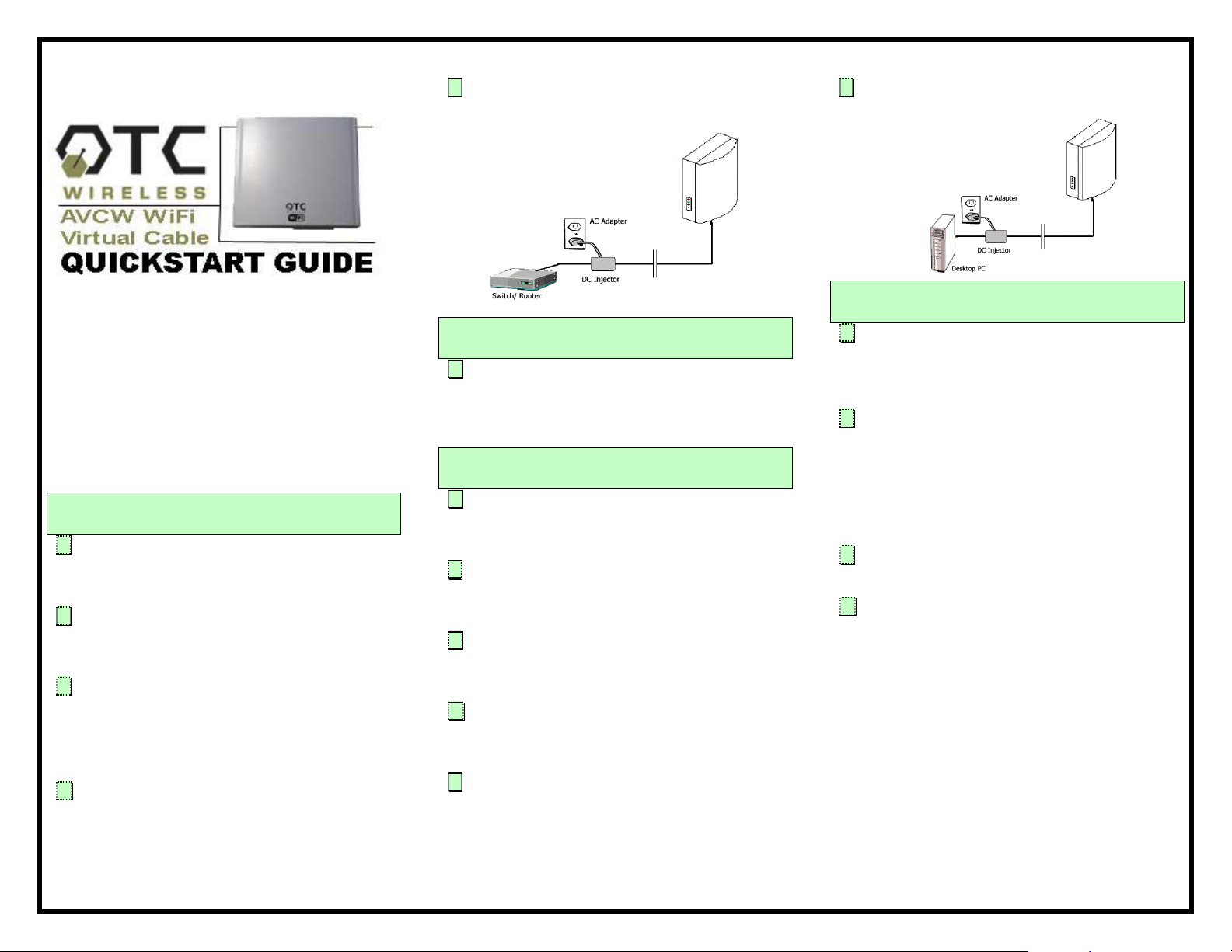
A. Connect the bundled 9V AC Adapter to the port
on the DC Injector labeled, DC. Connect the AC
Adapter to a wall outlet
B. Connect the black Cat5 cabl e that extends from
the AVCW unit labeled, “AP” to the port on the
DC Injector labeled, Radio.
C. Connect the (blue) crossover Cat5 cable from
your Hub or Switch to the port on the DC Injector
labeled, Network. If you are connecting the
Server to a DSL or cable modem or Rout er, use
the (white) straight-thru Cat5 cable.
D. Check to see that the yellow LED labe led, "Link"
is flashing periodically. If it is solid, try another
cable or switch to a crossover or straight-thru
cable as needed.
E. If the AVCW unit has an antenna connector
(AVCW-100), use an LMR-400 cable to connect
the unit to an external antenna.
Step 2: Position the AVCW-100/109/115
Virtual Cable Wi-Fi Access Point
A. Affix the AVCW-100, 109 or 115 Virtual Cable Wi-
Fi AP unit and the antenna (for AVCW-100) to a
mast or wall using the bundled installation
products and manuals.
Step 3: Connect the AVCW-200/209/215
Virtual Cable Wi-Fi Station
A. Connect the bundled 9V AC Adapter to the port
on the DC Injector labeled, DC. Connect the AC
Adapter a wall outlet.
B. Connect the black Cat5 cable that extends from
the AVC unit labeled, "Station" to the port on the
DC injector labeled, Radio.
C. Connect the bundled (white) Cat5 cable from
your PC to the port on the DC Injector labeled,
Network.
D. If the AVCW unit has an antenna connector (AVC-
200), use an LMR-400 cable to connect the unit
to an external antenna.
E. Check to see t hat the yellow LED labeled, "Link" is
flashing periodically. If it is solid, try another
cable or switch to a crossover or straight-thru
cable as needed.
F. Repeat step 3 for all other AVCW-200, 209 or
215 Virtual Cable Wi-Fi Station units if needed.
Step 4: Position the AVCW-200/209/215
Virtual Cable Wi-Fi Station
A. Affix the AVCW-200, 209 or 215 Virtual Cable Wi-
Fi Station unit and the antenna (AVCW-200) to a
mast or wall unit using the bundled OEM
installation products and manuals.
B. Affix the AVCW-200, 209 or 215 Virtual Cable Wi-
Fi Station so that the antenn a is aim ed dir ectly a t
the AVCW AP unit. If the AP is not in direct view,
re-position or rotate the AVCW-200, 209 or 215
Virtual Cable Wireless Station until the LED
indicator labeled "TX" turns on periodically. This
indicates communication with the AP unit.
C. Repeat step 4 for all other AVCW-200, 209 or
215 Virtual Cable Wi-Fi Station units if needed.
D. You are now able to connect with the AP unit. If
the AP unit is connected to a router, use a web
browser (e.g. Internet Explorer) to confirm a
wireless connection to the Internet. If the AP
unit is connected to a switch, use your network
browser (e.g. Network Neighborhood) to confirm
access to your Local area Ne twork.
If there is appears to be no communication, check
SSID and channel number which must be the same as
setting in the AP unit. Consult the Virtual Cable Wi-Fi
Manual included with your product.
For technical assistance, please call OTC Wireless at
(800) 770 - 6698 or visit OTC Website at
www.otcwireless.com.
AVC-W Wi-Fi Virtual Cable Quick Start Guide v 1.2
 Loading...