

Page 1
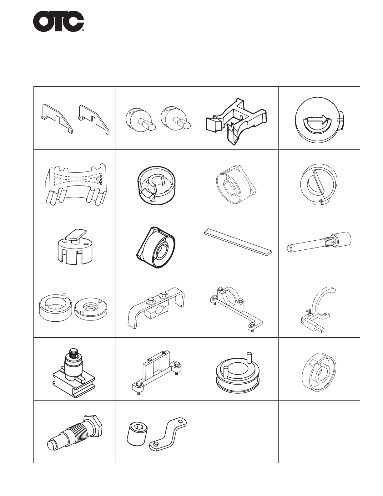
Parts List & Operating Instructions for
No. 6489
Ford
Cam and Valve Train Tool Kit
511532 (6009) 511555 (6020) 511533 (6466) 511534 (6467)
511535 (6468) 511536 (6469) 511537 (6470) 511538 (6471)
511539 (6472) 511540 (6473) 511541 (6474) 511542 (6475)
511543 & 511544 (6476) 511545 (6477) 511546 (6478) 511547 (6479)
511548 (6480) 511549 (6481) 511550 (6482) 511551 (6483)
511552 (6484) 511553 & 511554 (6485)
Page 2
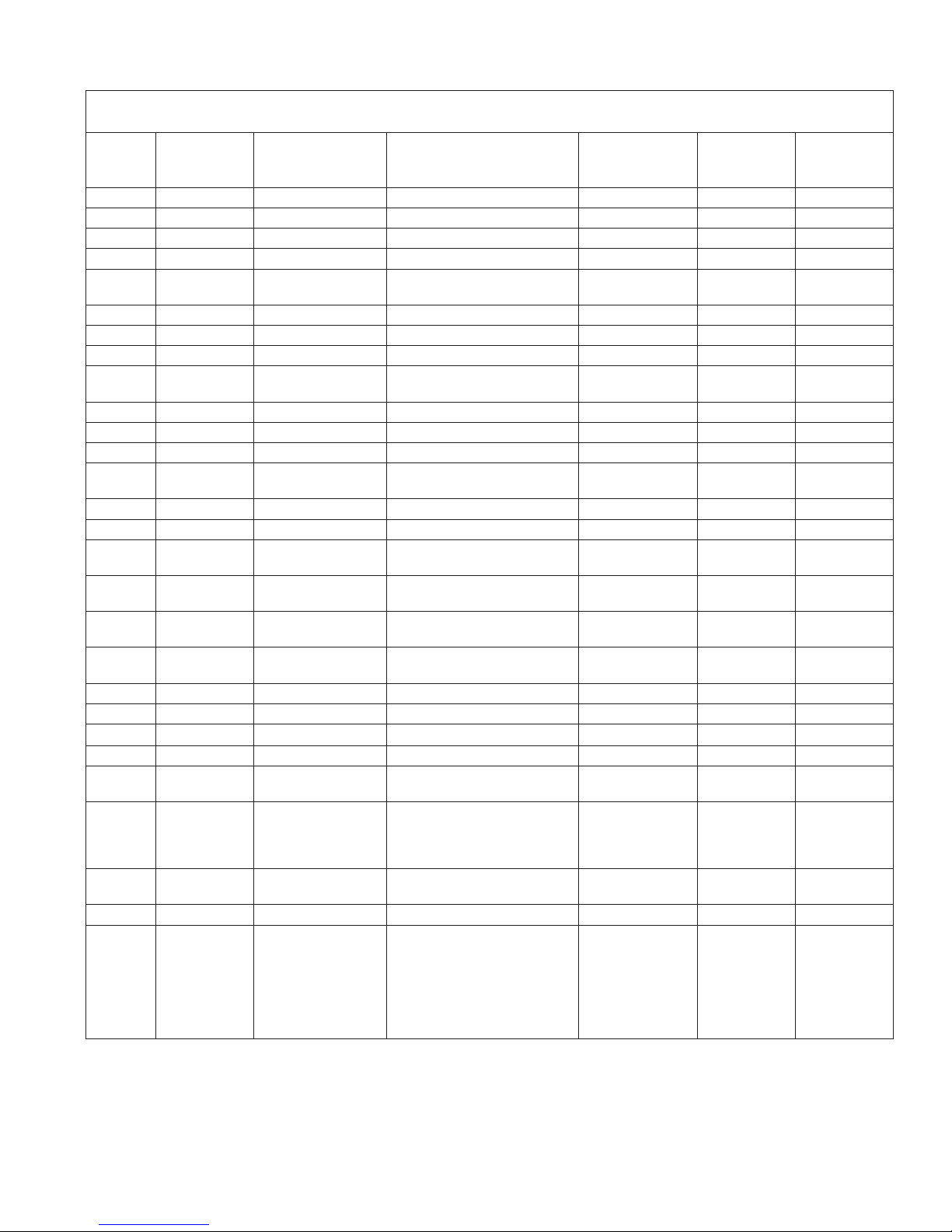
Ford Tool Application Chart
Ford
Year Model Engine Tool Description Part No.
American
Part No.
1995-1997 Aerostar 3.0L V6 Cam Sensor Synch Tool 6472 (511539) T95T-12200-A 303-529
1996-1998 Aerostar 4.0L V6 Cam Sensor Synch Tool 6472 (511539) T95T-12200-A 303-529
1994-2002 Contour 2.0L 4 cyl. VIN 3 Cam Alignment Tool 6474 (511541) T94P-6256-CH 303-465
1997-2002 Contour 2.0L 4 cyl. VIN 3 Crankshaft TDC Timing Pin 6475 (511542) T97P-6000-A 303-574
1999-2002 Cougar 2.0L VIN 3 Cam Alignment Tool
Crankshaft TDC Timing Pin
1997 Cougar 3.8L V6 Cam Sensor Synch Tool 6469 (511536) T96T-12200-A 303-562
1991-2008 Crown Victoria 4.6L 2V V8 Cam Positioning Tool 6009 (511532) T91P-6256-A 303-380
1992-2008 Crown Victoria 4.6L 2V V8 Cam Positioning Tool 6020 (511555) T92P-6256-A 303-413
1997-2002 Crown Victoria 4.6L VIN W Cam Positioning Tool
Cam Positioning Tool
1997-2008 Econoline 4.2L V6 Cam Sensor Synch Tool 6469 (511536) T96T-12200-A 303-562
1997-2009 Econoline 4.6L VIN W Cam Holding Tool 6477 (511545) T96T-6256-B 303-557
1997-2014 Econoline 4.6L VIN W Cam Positioning Tool 6020 (511555) T92P-6256-A 303-413
1997-1998 Econoline 4.6L & 5.4L V8, 6.8L V10 Cam Positioning Tool
Cam Positioning Tool
1997-2002 Econoline 4.6L & 5.4L Cam Positioning Tool 6476 (511543 & 4) T96T-6256-AR 303-S568
1997-2002 Econoline 5.4L V8 Cam Holding Tool 6477 (511545) T96T-6256-B 303-557
1997-2002 Econoline 6.8L V10 Cam Positioning Tool
Cam Holding Tool
2012-2014 Edge 2.0L VIN 9 Cam Alignment Tool
Crankshaft TDC Timing Pin
2001-2004 Escape 2.0L VIN B Cam Alignment Tool
Crankshaft TDC Timing Pin
2013-2014 Escape 2.0L VIN 9 Cam Alignment Tool
Crankshaft TDC Timing Pin
2005-2008 Escape 2.3L VIN Z Cam Alignment Tool 6474 (511541) T94P-6256-CH 303-465
2009-2014 Escape 2.5L VIN 7 Cam Alignment Tool 6474 (511541) T94P-6256-CH 303-465
2005-2008 Escape Hybrid 2.3L VIN H Cam Alignment Tool 6474 (511541) T94P-6256-CH 303-465
2009-2012 Escape Hybrid 2.5L VIN 3 Cam Alignment Tool 6474 (511541) T94P-6256-CH 303-465
1997-2002 Expedition 4.6L VIN W Cam Positioning Tool
Cam Positioning Tool
1997-2002 Expedition 5.4L Cam Positioning Tool
Cam Positioning Tool
Cam Positioning Tool
Cam Holding Tool
2012-2014 Explorer 2.0L VIN 9 Cam Alignment Tool
Crankshaft TDC Timing Pin
1996-1998 Explorer 4.0L V6 Cam Sensor Synch Tool 6472 (511539) T95T-12200-A 303-529
1997-2008 Explorer 4.0L SOHC VIN X Cam Gear Holding Tool
Crankshaft Holding Tool
Cam Holding Tool Adapter
Cam Holding Tool
Cam Gear Holding Tool Adapter
Timing Chain Tensioner Tool
Cam Gear Bolt Socket & Extension
6474 (511541)
6475 (511542)
6009 (511532)
6020 (511555)
6009 (511532)
6020 (511555)
6476 (511543 & 4)
6477 (511545)
6474 (511541)
6475 (511542)
6474 (511541)
6475 (511542)
6474 (511541)
6475 (511542)
6009 (511532)
6020 (511555)
6009 (511532)
6020 (511555)
6476 (511543 & 4)
6477 (511545)
6474 (511541)
6475 (511542)
6478 (511546)
6479 (511547)
6480 (511548)
6481 (511549)
6482 (511550)
6484 (511552)
6485 (511553 & 4)
T94P-6256-CH
T97P-6000-A
T91P-6256-A
T92P-6256-A
T91P-6256-A
T92P-6256-A
T96T-6256-AR
T96T-6256-B
T94P-6256-CH
T97P-6000-A
T94P-6256-CH
T97P-6000-A
T94P-6256-CH
T97P-6000-A
T91P-6256-A
T92P-6256-A
T91P-6256-A
T92P-6256-A
T96T-6256-AR
T96T-6256-B
T94P-6256-CH
T97P-6000-A
T97T-6256-B
T97T-6303-A
T97T-6256-D
T97T-6256-C
T97T-6256-A
T97T-6K254-A
T97T-6256-F, -G
Ford
Global Part
No.
303-465
303-574
303-380
303-413
303-380
303-413
303-S568
303-557
303-465
303-574
303-465
303-574
303-465
303-574
303-380
303-413
303-380
303-413
303-S568
303-557
303-465
303-574
303-564
303-573
303-576
303-577
303-578
303-571
303-565, -575
Page 3

Parts List & Operating Instructions
Ford Tool Application Chart
Ford
Year Model Engine Tool Description Part No.
American
Part No.
1997-2011 Explorer 4.0L SOHC V6 VIN E Cam Gear Holding Tool
Crankshaft Holding Tool
Cam Holding Tool Adapter
Cam Holding Tool
Cam Gear Holding Tool Adapter
Timing Chain Tensioner Tool
Cam Gear Bolt Socket & Extension
1999-2002 Explorer 4.0L Push Rod V6 Cam Sensor Synch Tool 6483 (511551) 303-638
1997-2002 Explorer 4.6L VIN W Cam Positioning Tool
Cam Positioning Tool
1996-1998 Explorer 5.0L V8 Cam Sensor Synch Tool 6469 (511536) T96T-12200-A 303-562
1999-2002 Explorer 5.0L V8 Cam Sensor Synch Tool 6470 (511537) 303-630
1997-2004 F-150 4.6L VIN 6 Cam Positioning Tool
Cam Positioning Tool
1997-2010 F-150 4.6L VIN W Cam Positioning Tool
Cam Positioning Tool
1997-2008 F-Series Truck 4.2L Cam Sensor Synch Tool 6469 (511536) T96T-12200-A 303-562
1997-1998 F-Series Truck 4.6L Cam Positioning Tool
Cam Positioning Tool
1997-2002 F-Series Truck 4.6L Cam Positioning Tool 6476 (511543 & 4) T96T-6256-AR 303-S568
1997-2009 F-Series Truck 4.6L VIN W Cam Holding Tool 6477 (511545) T96T-6256-B 303-557
1997-2002 F-Series Truck 5.4L Cam Positioning Tool
Cam Positioning Tool
Cam Positioning Tool
1997-2002 F-Series Truck 5.4L Cam Holding Tool 6477 (511545) T96T-6356-B 303-557
2012-2014 Focus 2.0L VIN 2 Cam Alignment Tool
Crankshaft TDC Timing Pin
2000-2004 Focus 2.0L VIN 3 Cam Alignment Tool
Crankshaft TDC Timing Pin
2002-2004 Focus 2.0L VIN 5 Cam Alignment Tool
Crankshaft TDC Timing Pin
2005-2011 Focus 2.0L VIN N Crankshaft TDC Timing Pin 6475 (511542) T97P-6000-A 303-574
2005-2012 Focus 2.0L VIN N Cam Alignment Tool 6474 (511541) T94P-6256-CH 303-465
2003-2007 Focus 2.3L VIN Z Cam Alignment Tool 6474 (511541) T94P-6256-CH 303-465
2004-2007 Freestar 3.9L VIN 6 Cam Sensor Synch Tool 6470 (511537) 303-630
2004-2007 Freestar 4.2L Cam Sensor Synch Tool 6469 (511536) T96T-12200-A 303-562
2013-2014 Fusion 2.0L Cam Alignment Tool
Crankshaft TDC Timing Pin
2006-2009 Fusion 2.3L VIN Z Cam Alignment Tool 6474 (511541) T94P-6256-CH 303-465
2010-2014 Fusion 2.5L VIN A Cam Alignment Tool 6474 (511541) T94P-6256-CH 303-465
2010-2014 Fusion Hybrid 2.5L VIN 3 Cam Alignment Tool 6474 (511541) T94P-6256-CH 303-465
1991-2008 Grand Marquis 4.6L 2V Cam Positioning Tool 6009 (511532) T91P-6256-A 303-380
1992-2008 Grand Marquis 4.6L 2V Cam Positioning Tool 6020 (511555) T92P-6256-A 303-413
1997-2002 Grand Marquis 4.6L VIN W Cam Positioning Tool
Cam Positioning Tool
2005-2008 Mariner 2.3L VIN Z Cam Alignment Tool 6474 (511541) T94P-6256-CH 303-465
2009-2012 Mariner 2.5L VIN 7 Cam Alignment Tool 6474 (511541) T94P-6256-CH 303-465
2005-2008 Mariner Hybrid 2.3L VIN H Cam Alignment Tool 6474 (511541) T94P-6256-CH 303-465
2009-2012 Mariner Hybrid 2.5L VIN 3 Cam Alignment Tool 6474 (511541) T94P-6256-CH 303-465
2006-2009 Milan 2.3L VIN Z Cam Alignment Tool 6474 (511541) T94P-6256-CH 303-465
2010-2011 Milan 2.5L Cam Alignment Tool 6474 (511541) T94P-6256-CH 303-465
6478 (511546)
6479 (511547)
6480 (511548)
6481 (511549)
6482 (511550)
6484 (511552)
6485 (511553 & 4)
6009 (511532)
6020 (511555)
6009 (511532)
6020 (511555)
6009 (511532)
6020 (511555)
6009 (511532)
6020 (511555)
6009 (511532)
6476 (511543 & 4)
6020 (511555)
6474 (511541)
6475 (511542)
6474 (511541)
6475 (511542)
6474 (511541)
6475 (511542)
6474 (511541)
6475 (511542)
6009 (511532)
6020 (511555)
T97T-6256-B
T97T-6303-A
T97T-6256-D
T97T-6256-C
T97T-6256-A
T97T-6K254-A
T97T-6256-F, -G
T91P-6256-A
T92P-6256-A
T91P-6256-A
T92P-6256-A
T91P-6256-A
T92P-6256-A
T91P-6256-A
T92P-6256-A
T91P-6256-A
T96T-6256-AR
T92P-6256-A
T94P-6256-CH
T97P-6000-A
T94P-6256-CH
T97P-6000-A
T94P-6256-CH
T97P-6000-A
T94P-6256-CH
T97P-6000-A
T91P-6256-A
T92P-6256-A
Ford
Global Part
No.
303-564
303-573
303-576
303-577
303-578
303-571
303-565, -575
303-380
303-413
303-380
303-413
303-380
303-413
303-380
303-413
303-380
303-S568
303-413
303-465
303-574
303-465
303-574
303-465
303-574
303-465
303-574
303-380
303-413
Page 4
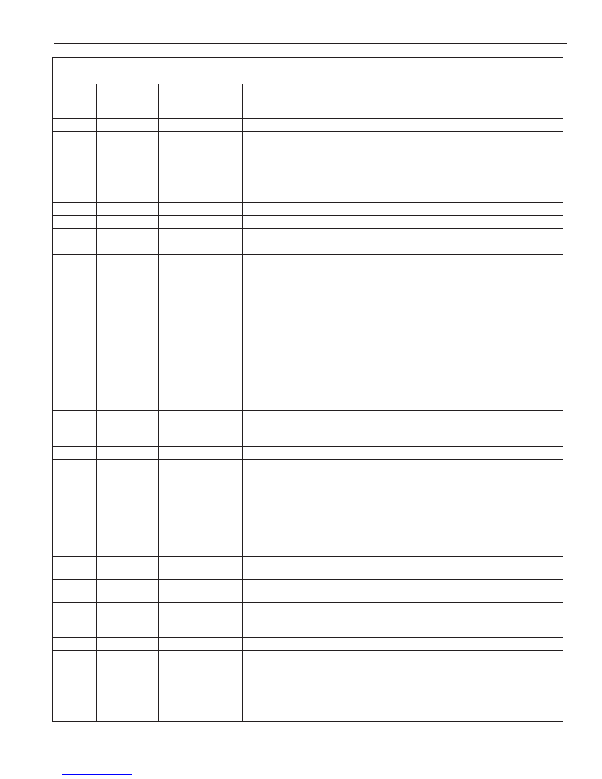
Parts List & Operating Instructions Form No. 107267
Ford Tool Application Chart
Year Model Engine Tool Description Part No.
Ford
American
Ford
Global Part
Part No.
2010-2012 Milan Hybrid 2.5L VIN 3 Cam Alignment Tool 6474 (511541) T94P-6256-CH 303-465
2014 MKT 2.0L Cam Alignment Tool
Crankshaft TDC Timing Pin
2012 MKX 2.0L VIN 9 Cam Alignment Tool 6474 (511541) T94P-6256-CH 303-465
2013-2014 MKZ 2.0L Cam Alignment Tool
Crankshaft TDC Timing Pin
2006-2009 MKZ 2.3L VIN Z Cam Alignment Tool 6474 (511541) T94P-6256-CH 303-465
2010-2012 MKZ 2.5L VIN A Cam Alignment Tool 6474 (511541) T94P-6256-CH 303-465
2010-2012 MKZ Hybrid 2.5L VIN 3 Cam Alignment Tool 6474 (511541) T94P-6256-CH 303-465
2004 Monterey 3.9L VIN 6 Cam Sensor Synch Tool 6470 (511537) 303-630
2004-2007 Monterey 4.2L Cam Sensor Synch Tool 6469 (511536) T96T-12200-A 303-562
1997-2008 Mountaineer 4.0L SOHC VIN X Cam Gear Holding Tool
Crankshaft Holding Tool
Cam Holding Tool Adapter
Cam Holding Tool
Cam Gear Holding Tool Adapter
Timing Chain Tensioner Tool
Cam Gear Bolt Socket & Extension
1997-2011 Mountaineer 4.0L SOHC V6 VIN E Cam Gear Holding Tool
Crankshaft Holding Tool
Cam Holding Tool Adapter
Cam Holding Tool
Cam Gear Holding Tool Adapter
Timing Chain Tensioner Tool
Cam Gear Bolt Socket & Extension
1999-2002 Mountaineer 4.0L Push Rod V6 Cam Sensor Synch Tool 6483 (511551) 303-638
1997-2005 Mountaineer 4.6L VIN W Cam Positioning Tool
Cam Positioning Tool
1996-1998 Mountaineer 5.0L V8 Cam Sensor Synch Tool 6469 (511536) T96T-1220-A 303-562
1999-2002 Mountaineer 5.0L V8 Cam Sensor Synch Tool 6470 (511537) 303-630
1996-1998 Mustang 3.8L V6 Cam Sensor Synch Tool 6469 (511536) T96T-12200-A 303-562
1999-2004 Mustang 3.8L V6 Cam Sensor Synch Tool 6470 (511537) 303-630
2005-2010 Mustang 4.0L SOHC VIN N Cam Gear Holding Tool
Crankshaft Holding Tool
Cam Holding Tool Adapter
Cam Holding Tool
Cam Gear Holding Tool Adapter
Timing Chain Tensioner Tool
Cam Gear Bolt Socket & Extension
1997-2002 Mustang 4.6L VIN W Cam Positioning Tool
Cam Positioning Tool
1996-2004 Mustang 4.6L VIN X Cam Positioning Tool
Cam Positioning Tool
2003-2004 Mustang 4.6L VIN Y Cam Positioning Tool
Cam Positioning Tool
1994-2002 Mystique 2.0L 4 cyl. VIN 3 Cam Alignment Tool 6474 (511541) T94P-6256-CH 303-465
1997-2002 Mystique 2.0L 4 cyl. VIN 3 Crankshaft TDC Timing Tool 6475 (511542) T97P-6000-A 303-574
1998-1999 Navigator 5.4L Cam Positioning Tool
Cam Positioning Tool
1998-2002 Navigator 5.4L Cam Positioning Tool
Cam Holding Tool
2001-2011 Ranger 2.3L VIN D Cam Alignment Tool 6474 (511541) T94P-6256-CH 303-465
1995-1997 Ranger 3.0L V6 Cam Sensor Synch Tool 6472 (511539) T95T-12200-A 303-529
6474 (511541)
6475 (511542)
6474 (511541)
6475 (511542)
6478 (511546)
6479 (511547)
6480 (511548)
6481 (511549)
6482 (511550)
6484 (511552)
6485 (511553 & 4)
6478 (511546)
6479 (511547)
6480 (511548)
6481 (511549)
6482 (511550)
6484 (511552)
6485 (511553 & 4)
6009 (511532)
6020 (511555)
6478 (511546)
6479 (511547)
6480 (511548)
6481 (511549)
6482 (511550)
6484 (511552)
6485 (511553 & 4)
6009 (511532)
6020 (511555)
6009 (511532)
6020 (511555)
6009 (511532)
6020 (511555)
6009 (511532)
6020 (511555)
6476 (511543 & 4)
6477 (511545)
T94P-6256-CH
T97P-6000-A
T94P-6256-CH
T97P-6000-A
T97T-6256-B
T97T-6303-A
T97T-6256-D
T97T-6256-C
T97T-6256-A
T97T-6K254-A
T97T-6256-F, -G
T97T-6256-B
T97T-6303-A
T97T-6256-D
T97T-6256-C
T97T-6256-A
T97T-6K254-A
T97T-6256-F, -G
T91P-6256-A
T92P-6256-A
T97T-6256-B
T97T-6303-A
T97T-6256-D
T97T-6256-C
T97T-6256-A
T97T-6K254-A
T97T-6256-F, -G
T91P-6256-A
T92P-6256-A
T91P-6256-A
T92P-6256-A
T91P-6256-A
T92P-6256-A
T91P-6256-A
T92P-6256-A
T96T-6256-AR
T96T-6256-B
303-465
303-574
303-465
303-574
303-564
303-573
303-576
303-577
303-578
303-571
303-565, -575
303-564
303-573
303-576
303-577
303-578
303-571
303-565, -575
303-380
303-413
303-564
303-573
303-576
303-577
303-578
303-571
303-565, -575
303-380
303-413
303-380
303-413
303-380
303-413
303-380
303-413
303-S568
303-557
No.
Page 5

Parts List & Operating Instructions
Ford Tool Application Chart
Ford
Year Model Engine Tool Description Part No.
American
Part No.
1998-2008 Ranger 3.0L V6 Cam Sensor Synch Tool 6473 (511540) 303-589
1996-1998 Ranger 4.0L V6 Cam Sensor Synch Tool 6472 (511539) T95T-12200-A 303-529
1997-2011 Ranger 4.0L SOHC VIN E Cam Gear Holding Tool
Crankshaft Holding Tool
Cam Holding Tool Adapter
Cam Holding Tool
Cam Gear Holding Tool Adapter
Timing Chain Tensioner Tool
Cam Gear Bolt Socket & Extension
1997-2008 Ranger 4.0L SOHC VIN X Cam Gear Holding Tool
Crankshaft Holding Tool
Cam Holding Tool Adapter
Cam Holding Tool
Cam Gear Holding Tool Adapter
Timing Chain Tensioner Tool
Cam Gear Bolt Socket & Extension
2003-2011 Ranger 4.0L SOHC Cam Gear Bolt Socket & Extension 6485 (511553 & 4) T97T-6256-F, -G 303-565, -575
1999-2000 Ranger 4.0L Push Rod Cam Sensor Synch Tool 6483 (511551) 303-638
1996-1997 Sable 3.0L V6 2V Cam Sensor Synch Tool 6472 (511539) T95T-12200-A 303-529
1998-2005 Sable 3.0L V6 VIN U Cam Sensor Synch Tool 6473 (511540) 303-589
1998-2006 Sable 3.0L V6 VIN Z Cam Sensor Synch Tool 6473 (511540) 303-589
2013-2014 Taurus 2.0L Cam Alignment Tool
Crankshaft TDC Timing Pin
1996-1997 Taurus 3.0L V6 2V Cam Sensor Synch Tool 6472 (511539) T95T-12200-A 303-529
1998-2005 Taurus 3.0L V6 VIN U Cam Sensor Synch Tool 6473 (511540) 303-589
1998-2006 Taurus 3.0L V6 VIN Z Cam Sensor Synch Tool 6473 (511540) 303-589
1997 Thunderbird 3.8L V6 Cam Sensor Synch Tool 6469 (511536) T96T-12200-A 303-562
1997-2002 Town Car 4.6L VIN W Cam Positioning Tool
Cam Positioning Tool
2010-2013 Transit 2.0L VIN N Cam Alignment Tool
Crankshaft TDC Timing Pin
1995-1997 Windstar 3.0L V6 Cam Sensor Synch Tool 6472 (511539) T95T-12200-A 303-529
1998-2003 Windstar 3.0L V6 VIN U Cam Sensor Synch Tool 6473 (511540) 303-589
1996-1998 Windstar 3.8L V6 Cam Sensor Synch Tool 6469 (511536) T96T-12200-A 303-562
1999-2003 Windstar 3.8L V6 Cam Sensor Synch Tool 6470 (511537) 303-630
2006-2009 Zephyr 2.3L VIN Z Cam Alignment Tool 6474 (511541) T94P-6256-CH 303-465
6478 (511546)
6479 (511547)
6480 (511548)
6481 (511549)
6482 (511550)
6484 (511552)
6485 (511553 & 4)
6478 (511546)
6479 (511547)
6480 (511548)
6481 (511549)
6482 (511550)
6484 (511552)
6485 (511553 & 4)
6474 (511541)
6475 (511542)
6009 (511532)
6020 (511555)
6474 (511541)
6475 (511542)
T97T-6256-B
T97T-6303-A
T97T-6256-D
T97T-6256-C
T97T-6256-A
T97T-6K254-A
T97T-6256-F, -G
T97T-6256-B
T97T-6303-A
T97T-6256-D
T97T-6256-C
T97T-6256-A
T97T-6K254-A
T97T-6256-F, -G
T94P-6256-CH
T97P-6000-A
T91P-6256-A
T92P-6256-A
T94P-6256-CH
T97P-6000-A
Ford
Global Part
No.
303-564
303-573
303-576
303-577
303-578
303-571
303-565, -575
303-564
303-573
303-576
303-577
303-578
303-571
303-565, -575
303-465
303-574
303-380
303-413
303-465
303-574
Page 6
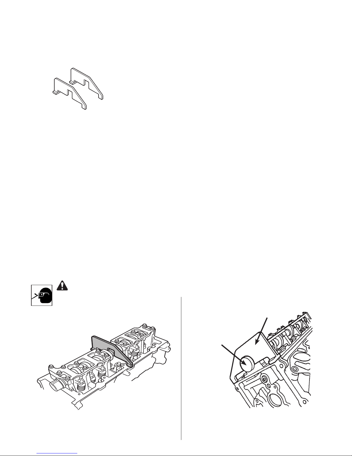
511532 (6009) Ford Camshaft Positioning Tool
Application: 1991 – 2008 4.6L 2V Crown Victoria (V8), Grand Marquis
1997 – 1998 4.6L & 5.4L V8, 6.8L V10 Econoline
1997 – 2002 5.4L Expedition
1997 – 2002 4.6L Expedition, Explorer, Crown Victoria,
Grand Marquis, Town Car (VIN W)
1997 – 2004 4.6L F-150 (VIN 6)
1997 – 2010 4.6L F-150 (VIN W)
same as
Ford No. 303-380
(T91P-6256-A)
Note: The 1991 4.6L 2V V8 application does not require the use of tool No. 511555 (6020).
1997 – 2002 5.4L F-Series Truck
1997 – 2005 4.6L Mountaineer (VIN W)
1997 – 2002 4.6L Mustang (VIN W)
CAUTION: To prevent damage to valves and pistons, do NOT rotate the crankshaft and/or camshaft(s)
when removing timing chain(s) and installing cylinder heads. Because this is not a free-wheeling
engine, if it has "jumped time," there will be damage to the valves and/or pistons, which will require
the removal of the cylinder heads. The cam sprocket should be disassembled from the camshaft only
when one of the components must be replaced.
1. Remove all necessary components to access the timing chains.
2. Rotate the engine to No. 1 TDC.
3. Assemble tools :
• 1991 4.6L 2V V8 : Refer to Figure 1. Install No. 511532 (6009) on ats of the camshaft to prevent accidental
rotation of the camshafts.
• All other applications : Refer to Figure 2. Install No. 511532 (6009) and Cam Positioning Tool No. 511555
(6020) into each camshaft end before removing (or installing) timing chain tensioners and chains —this
prevents valve train damage.
4. Perform camshaft service as required.
5. Refer to the vehicle service manual for the correct camshaft-to-crankshaft timing procedure.
1997 – 1998 4.6L F-Series Truck
1996 – 2004 4.6L Mustang (VIN X)
2003 – 2004 4.6L Mustang (VIN Y)
1998 – 1999 5.4L Navigator
WARNING: Wear eye
protection that meets ANSI
Z87.1 and OSHA standards.
Figure 1
The 1991 4.6L 2V V8 application does not require
the use of tool No. 6020.
No. 511532 (6009)
Ford Camshaft Positioning Tool
No. 511555 (6020)
Ford Camshaft
Positioning Tool
Figure 2
All other applications.
Page 7
Parts List & Operating Instructions
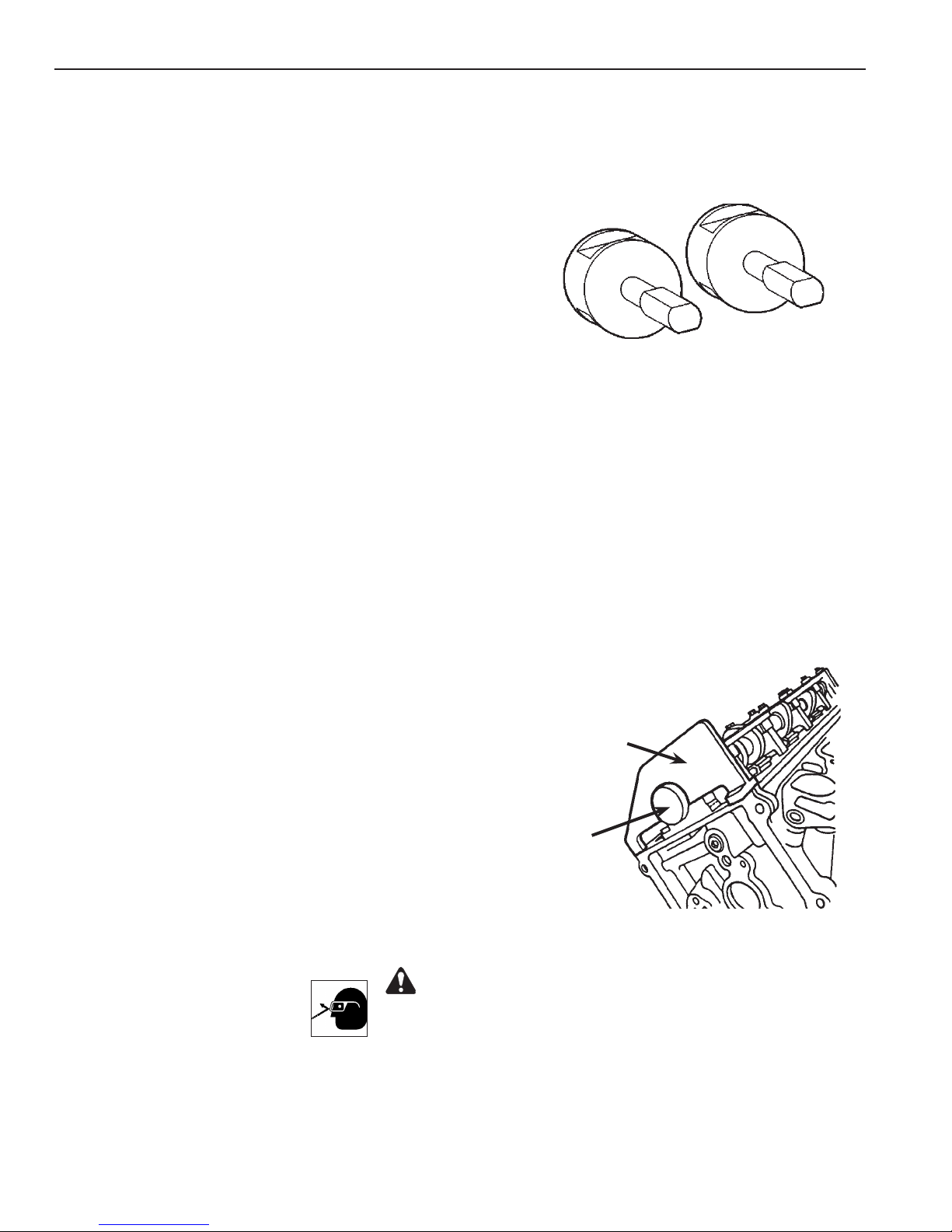
511555 (6020) Ford Camshaft Positioning Tool
Application: 1992 – 2008 4.6L 2V Crown Victoria (V8), Grand Marquis
1997 – 2002 4.6L Crown Victoria, Expedition, Explorer
Grand Marquis, Town Car (VIN W)
1997 – 1998 4.6L & 5.4L V8, 6.8L V10 Econoline
1997 – 2012 4.6L Econoline (VIN W)
1997 – 2002 5.4L Expedition
1997 – 2004 4.6L F-150 (VIN 6)
1997 – 2010 4.6L F-150 (VIN W)
1997 – 1998 4.6L F-Series Truck
1997 – 2002 5.4L F-Series Truck
1997 – 2005 4.6L Mountaineer (VIN W)
1997 – 2002 4.6L Mustang (VIN W)
1996 – 2004 4.6L Mustang (VIN X)
2003 – 2004 4.6L Mustang (VIN Y)
1998 – 1999 5.4L Navigator
Note: Tool No. 511555 (6020; same as Ford No. 303-413/T92P-6256-A) must be used with tool
No. 511532 (6009; same as Ford No. 303-380/T91P-6256-A).
CAUTION: To prevent damage to valves and pistons, DO NOT rotate the crankshaft and/or camshaft(s)
when removing the timing chain(s) and installing the cylinder heads. Because this is not a free-wheeling
engine, if it has "jumped time" there will be damage to the valves and/or pistons, which will require the removal
of the cylinder heads. The cam sprocket should be disassembled from the camshaft only when one of the
components must be replaced.
1. Remove all necessary components to access the timing chains.
2. Rotate the engine to No. 1 top dead center.
3. Disassembly: Install Camshaft Positioning
Tool (511555/6020) and Cam Positioning Tool
(511532/6009) into each camshaft end, as
shown, before removing timing chain tensioners
and chains to prevent valve train damage.
4. Assembly: Install Camshaft Positioning Tool
(511555/6020) and Cam Positioning Tool
(511532/6009) into each camshaft end, as shown,
before installing timing chains and tensioners to
prevent valve train damage.
WARNING: Wear eye
protection that meets ANSI
Z87.1 and OSHA standards.
No. 511532 (6009)
Ford Camshaft
Positioning Tool
No. 511555 (6020)
Ford Camshaft
Positioning Tool
Page 8
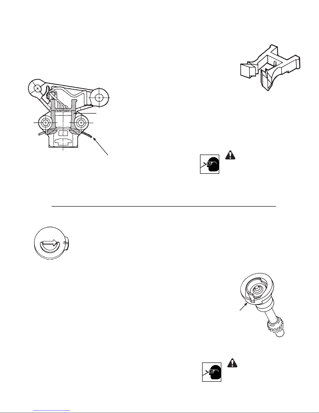
511533 (6466) Ford Crankshaft Sensor Positioner
Application: 1989 – 1997 Ford Ranger w/ 2.3L, 4 cyl., dual plug engine
Note: Same as Ford No. 303-354 (T89P-6316-A).
1. Install Crankshaft Sensor Positioner
No. 6466 (511533) on sensor as shown.
2. Rotate crankshaft so outer vane
on crankshaft pulley hub assembly
engages both sides of tool. Tighten
No. 6466
(511533)
sensor assembly retaining bolts to
specications.
3. Rotate crankshaft so vane on crankshaft
pulley hub assembly is no longer
engaged in tool. Remove tool.
Outer vane of
crankshaft pulley
hub assembly.
WARNING: Wear eye
protection that meets ANSI
Z87.1 and OSHA standards.
511534 (6467) Ford Camshaft Sensor Synchronizer Tool
Application: 1990 – 1997 3.8L V6 Thunderbird/Cougar
1989 – 1995 3.8L V6 Supercharged Thunderbird/Cougar
1994 – 1998 3.8L V6 Mustang
1998 3.8L V6 Windstar
Note: Same as Ford No. 303-358 (T89P-12200-A).
CAUTION: Before removing the camshaft sensor housing
assembly, note the position of the camshaft sensor electrical
connector. The connector MUST be reassembled in the same
position during installation.
1. Rotate crankshaft to set No. 1 cylinder at 26° after top dead
center of the compression stroke.
2. Engage camshaft sensor housing vane in slot of tool No. 6467
(511534).
3. Rotate tool on camshaft sensor housing until tool engages housing
notch. (Tool should be square and in contact with entire top of
housing.)
4. Install camshaft sensor housing and tool assembly into engine
according to instructions in the vehicle service manual. Torque
fasteners to factory specications.
Camshaft
Sensor
Housing
WARNING: Wear eye
protection that meets ANSI
Z87.1 and OSHA standards.
Page 9
Parts List & Operating Instructions
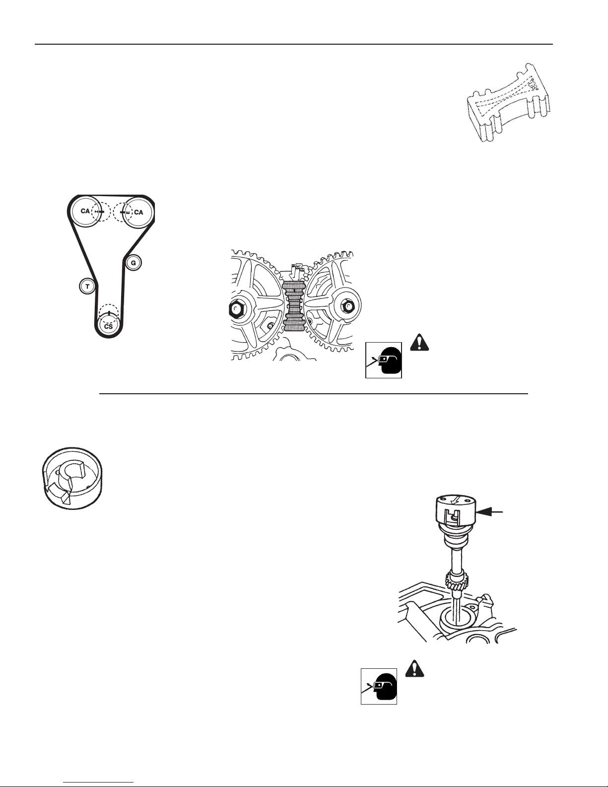
511535 (6468) Ford Camshaft Pulley Holding Tool
Application: 1993 – 1997 Ford Probe w/ 2.0L, 4 cyl., engine
Note: Same as Ford No. 303-398 (T92C-6256-AH).
1. Rotate engine to align camshaft
timing marks with crankshaft
timing marks.
2. Insert No. 6468 (511535)
between intake and exhaust cam
pulleys. The tool will t correctly
only one way. The side of tool
marked UP must be facing the
technician and top of engine.
No. 6468 (511535)
3. Follow vehicle service manual
procedure to service timing belt
as required. Remove tool when
nished.
WARNING: Wear eye
protection that meets ANSI
Z87.1 and OSHA standards.
511536 (6469) Ford Camshaft Sensor Synchronizer Tool
Application: 1997 3.8L V6 Cougar, Thunderbird
1997 – 2008 4.2L V6 Econoline, F-Series Truck
1996 – 1998 5.0L V8 Ford Explorer, Mercury Mountaineer
2004 – 2007 4.2L Freestar, Monterey
1996 – 1998 3.8L V6 Mustang, Windstar
Note: Same as Ford No. 303-562 (T96T-12200-A).
CAUTION: Before removing the camshaft sensor housing
assembly, note the position of the camshaft sensor
electrical connector. To prevent equipment damage, the
connector MUST be reassembled in the same position
during installation.
1. Rotate crankshaft to set No. 1 cylinder at top dead center of
the compression stroke.
2. Engage camshaft sensor housing vane in slot of tool No.
511536 (6469).
3. Rotate tool on camshaft sensor housing until tool engages
housing notch. (Tool should be square and in contact with
entire top of housing.)
4. Install camshaft sensor housing and tool assembly into engine
according to instructions in the vehicle service manual. Torque
fasteners to factory specications.
No. 511536
(6469)
Camshaft
Sensor
Housing
WARNING: Wear eye
protection that meets ANSI
Z87.1 and OSHA standards.
Page 10
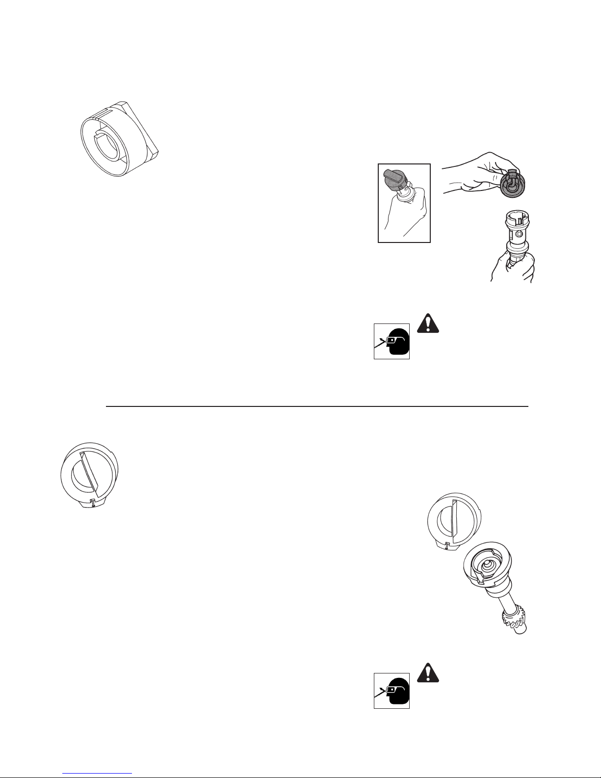
511537 (6470) Ford Camshaft Sensor Synchronizer Tool
Application: 1999 – 2002 5.0L V8 Explorer, Mountaineer
2004 – 2007 3.9L Freestar (VIN 6)
2004 3.9L Monterey (VIN 6)
1999 – 2004 3.8L V6 Mustang
1999 – 2003 3.8L V6 Windstar
Note: Same as Ford No. 303-630.
CAUTION: Before removing the camshaft sensor housing
assembly, note the position of the camshaft sensor electrical
connector. To prevent equipment damage, the connector
Camshaft
Sensor
Housing
MUST be reassembled in the same position during installation.
1. Rotate crankshaft to set No. 1 cylinder at top dead center of
compression stroke.
2. Engage camshaft sensor housing vane in slot of tool No. 511537
(6470).
3. Rotate tool on camshaft sensor housing until tool engages
housing notch. (Tool should be square and in contact with entire
top of housing.)
4. Install camshaft sensor housing and tool assembly into engine
WARNING: Wear eye
protection that meets ANSI
Z87.1 and OSHA standards.
according to instructions in the vehicle service manual. Torque
fasteners to factory specications.
511538 (6471) Ford Camshaft Sensor Synchronizer Tool
No. 511537
(6470)
Application: 1993 – 1995 3.0L V6 Ford Taurus/Mercury Sable
Note: Same as Ford No. 303-453 (T93P-12200-A).
CAUTION: Before removing the camshaft sensor housing
assembly, note the position of the camshaft sensor electrical
connector. The connector MUST be reassembled in the same
position during installation.
1. Rotate crankshaft to set No. 1 cylinder at top dead center of
compression stroke.
2. Engage camshaft sensor housing vane in slot of tool No. 6471
(511538).
3. Rotate tool on camshaft sensor housing until tool engages housing
notch. (Tool should be square and in contact with entire top of
housing.)
4. Install camshaft sensor housing and tool assembly into engine
according to instructions in the vehicle service manual. Torque
fasteners to factory specications.
No. 6471
(511538)
Camshaft
Sensor
Housing
WARNING: Wear eye
protection that meets ANSI
Z87.1 and OSHA standards.
Page 11
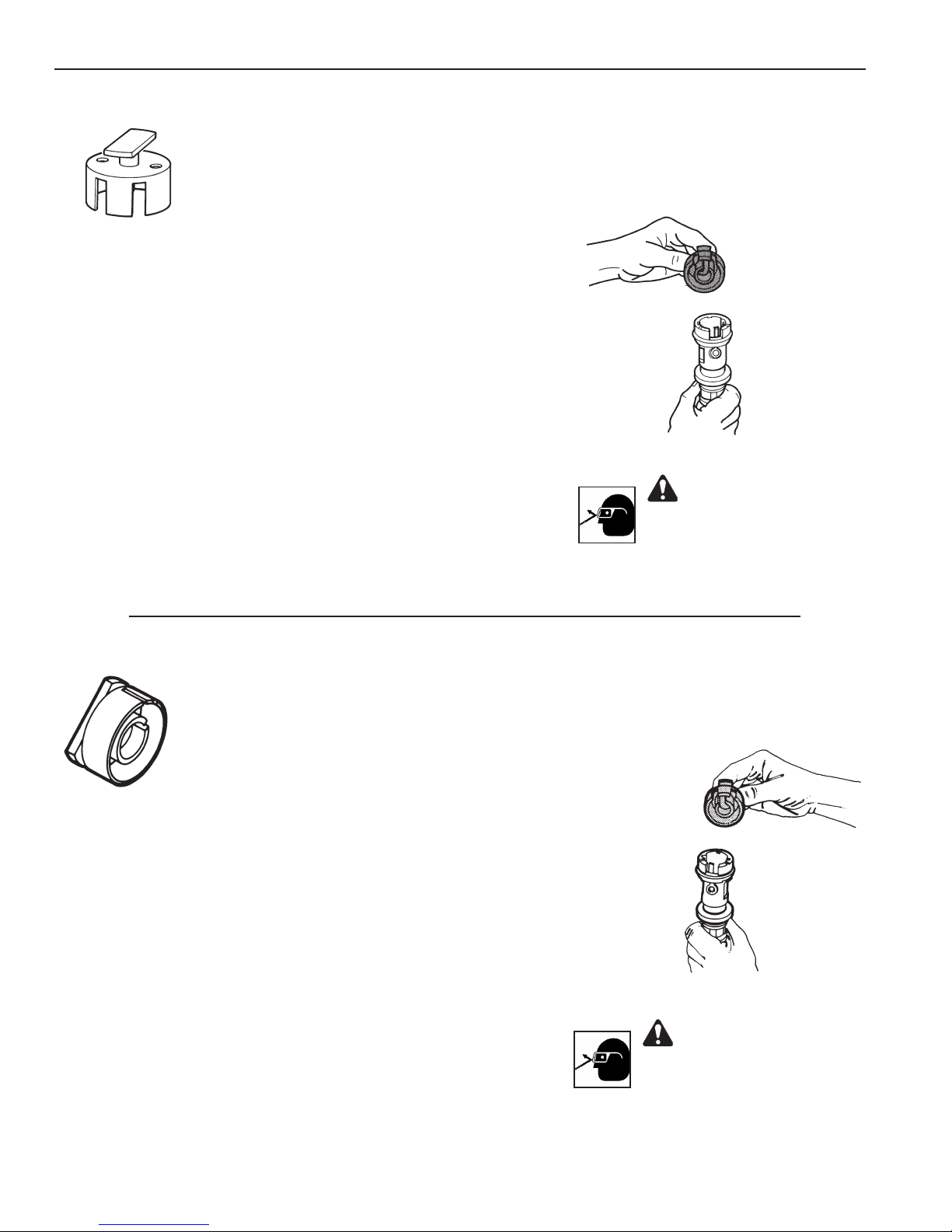
Parts List & Operating Instructions
511539 (6472) Ford Camshaft Positioning Tool Set
Application: 1995 – 1997 3.0L V6 Aerostar, Ranger, Windstar
1996 – 1998 4.0L V6 Aerostar, Explorer, Ranger
1996 – 1997 3.0L V6 2V Sable, Taurus
CAUTION: Before removing the camshaft sensor housing
assembly, note the position of the camshaft sensor
electrical connector. To prevent equipment damage, the
connector MUST be reassembled in the same position
during installation.
1. Rotate crankshaft to set No. 1 cylinder at TDC of
compression stroke.
2. Engage camshaft sensor housing vane in slot of tool No.
511539 (6472).
3. Rotate tool on camshaft sensor housing until tool engages
housing notch. (Tool should be square and in contact with
entire top of housing.)
4. Install camshaft sensor housing and tool assembly into
engine according to instructions in the vehicle service
manual. Torque fasteners to factory specications.
511539
WARNING: Wear eye
protection that meets ANSI
Z87.1 and OSHA standards.
No. 511539
(6472)
511540 (6473) Ford Camshaft Sensor Synchronizer Tool
Application: 1998 – 2008 3.0L V6 Ranger
1998 – 2005 3.0L V6 Sable, Taurus (VIN U)
1998 – 2006 3.0L V6 Sable, Taurus (VIN Z)
1998 – 2003 3.0L V6 Windstar
Note: Same as Ford No. 303-589.
CAUTION: Before removing the camshaft sensor housing
assembly, note the position of the camshaft sensor
electrical connector. To prevent equipment damage, the
connector MUST be reassembled in the same position
during installation.
1. Rotate crankshaft to set No. 1 cylinder at top dead center
of compression stroke.
2. Engage camshaft sensor housing vane in slot of tool No.
511540 (6473).
3. Rotate tool on camshaft sensor housing until tool engages
housing notch. (Tool should be square and in contact with
entire top of housing.)
4. Install camshaft sensor housing and tool assembly into
engine according to instructions in the vehicle service
manual. Torque fasteners to factory specications.
No. 511540
(6473)
Camshaft
Sensor
Housing
WARNING: Wear eye
protection that meets ANSI
Z87.1 and OSHA standards.
Page 12
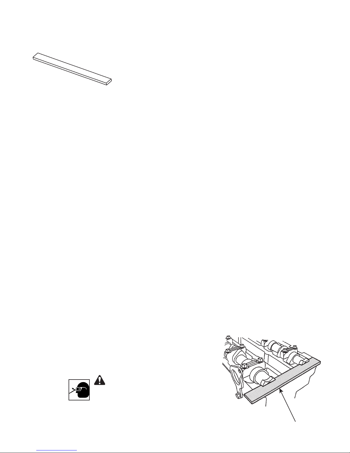
511541 (6474) Ford Camshaft Alignment Tool
Application: 1994 – 2002 2.0L 4 cyl. Contour, Mystique (VIN 3)
1999 – 2002 2.0L Cougar (VIN 3)
2012 – 2014 2.0L Edge, Explorer (VIN 9)
2001 – 2004 2.0L Escape (VIN B)
2013 – 2014 2.0L Escape (VIN 9), Fusion, MKZ, Taurus
2005 – 2008 2.3L Escape, Mariner (VIN Z)
2009 – 2014 2.5L Escape (VIN 7)
2005 – 2008 2.3L Escape Hybrid, Mariner Hybrid (VIN H)
2009 – 2012 2.5L Escape Hybrid, Mariner Hybrid (VIN 3)
2012 – 2014 2.0L Focus (VIN 2)
2000 – 2004 2.0L Focus (VIN 3)
2002 – 2004 2.0L Focus (VIN 5)
2005 – 2012 2.0L Focus (VIN N)
2003 – 2007 2.3L Focus (VIN Z)
2006 – 2009 2.3L Fusion, Milan, MKZ, Zephyr (VIN Z)
2010 – 2014 2.5L Fusion (VIN A)
2010 – 2014 2.5L Fusion Hybrid (VIN 3)
2009 – 2012 2.5L Mariner (VIN 7)
2010 – 2011 2.5L Milan
2010 – 2012 2.5L Milan Hybrid, MKZ Hybrid (VIN 3)
2014 2.0L MKT
2012 2.0L MKX (VIN 9)
2010 – 2012 2.5L MKZ (VIN A)
2001 – 2011 2.3L Ranger (VIN D)
2010 – 2013 2.0L Transit (VIN N)
Note:
Same as Ford No. 303-465 (T94P-6256-CH).
•
The camshaft timing slots are offset. If the
CAUTION: The Camshaft Alignment Tool is for
camshaft alignment only. Using this tool to
prevent rotation can result in engine damage.
1. Rotate engine to top dead center on the No. 1 cylinder.
2. Align camshafts by installing tool No. 511541 (6474) into the slots at the rear of the camshafts as shown.
3. Service the timing belt as required according to instructions in the vehicle service manual.
4. Torque fasteners to factory specications.
5. Remove the tool.
WARNING: Wear eye
protection that meets ANSI
Z87.1 and OSHA standards.
•
camshaft alignment timing tool cannot be installed,
rotate the crankshaft one complete revolution
clockwise to correctly position the camshafts.
No. 511541
(6474)
Page 13
Parts List & Operating Instructions
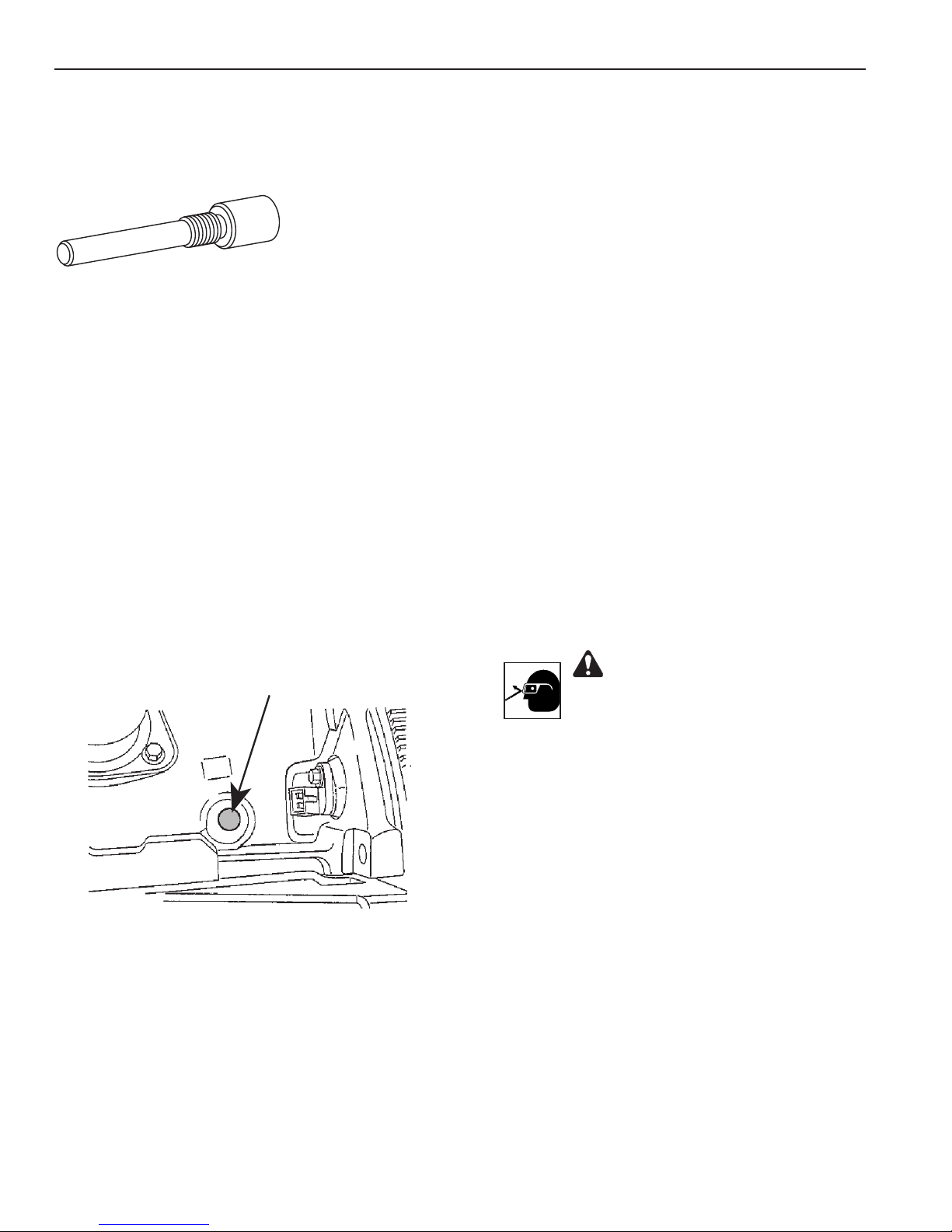
511542 (6475) Ford Crankshaft TDC Timing Pin
Application: 1997 – 2002 2.0L 4 cyl. Contour, Mystique (VIN 3)
1999 – 2002 2.0L Cougar (VIN 3)
2012 – 2014 2.0L Edge, Explorer (VIN 9)
2001 – 2004 2.0L Escape (VIN B)
2013 – 2014 2.0L Escape (VIN 9), Fusion, MKZ, Taurus
2012 – 2014 2.0L Focus (VIN 2)
2000 – 2004 2.0L Focus (VIN 3)
2002 – 2004 2.0L Focus (VIN 5)
2005 – 2011 2.0L Focus (VIN N)
2014 2.0L MKT
2010 – 2012 2.0L Transit (VIN N)
CAUTION: To prevent damage to the engine, remove the No. 511542 (6475) timing pin from the engine
and reinstall the access plug BEFORE cranking the engine.
1. Rotate crankshaft to set No. 1 cylinder on TDC of compression stroke.
2. Remove the access plug from the engine and install tool No. 511542 (6475) timing pin as shown. (The
pin will completely thread into the hole when the engine is at TDC on the No. 1 cylinder.)
3. Service the timing belt as required according to vehicle service manual procedures.
4. Torque fasteners to factory specications.
No. 6475
(511542)
WARNING: Wear eye
protection that meets ANSI
Z87.1 and OSHA standards.
Page 14
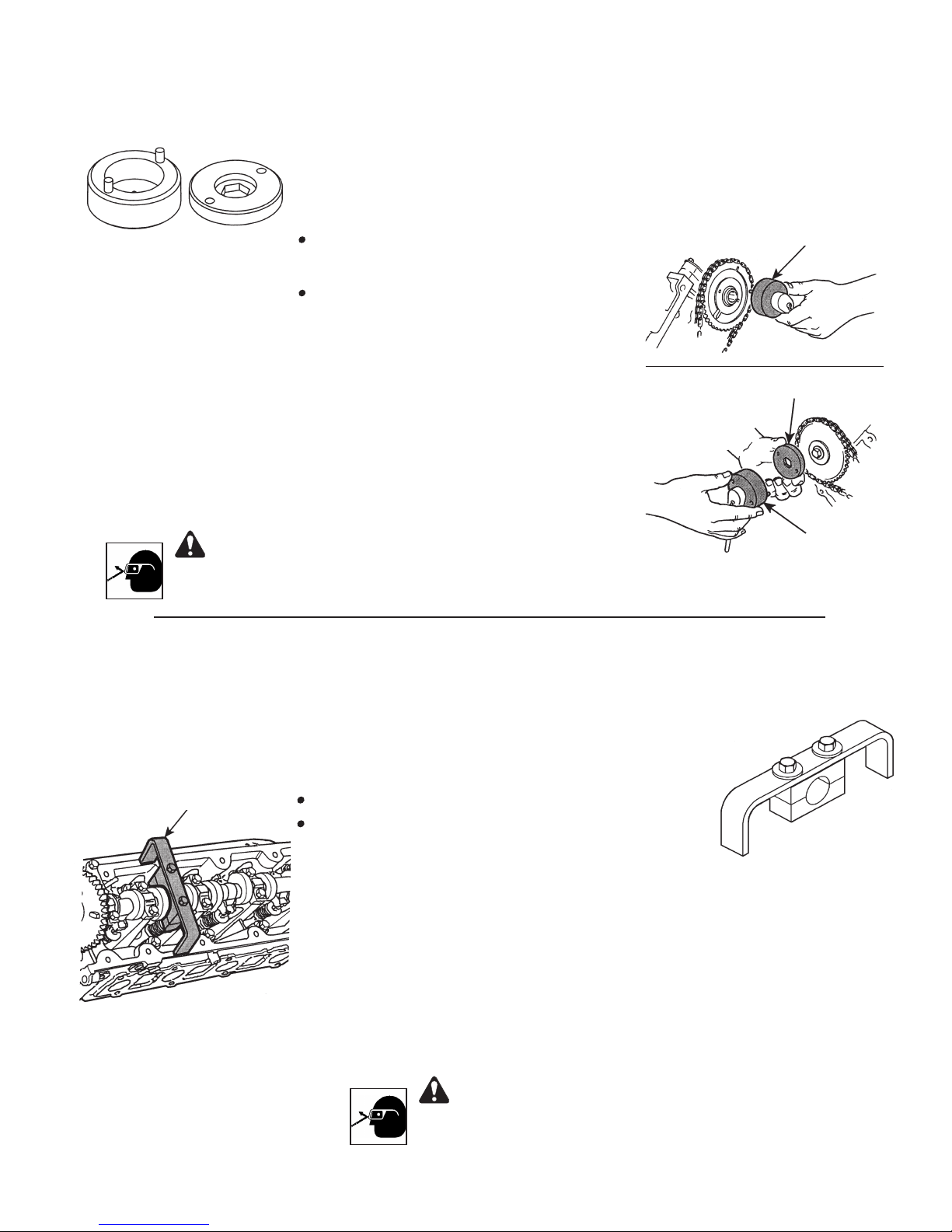
511543 / 511544 (6476) Ford Camshaft Positioning Tool Set
Application: 1997 – 2002 4.6L Econoline, F-Series Truck (VIN W)
1997 – 2002 5.4L Econoline, Expedition, F-Series Truck
1997 – 2002 6.8L V10 Econoline
1998 – 2002 5.4L Navigator
Note:
511543 511544
• 511543 is the same as Ford No. 303-569
(T96T-6256-AR1) and 511544 is the same
as Ford No. 303-570 (T96T-6256-AR2).
• This tool is used with No. 6477 (511545)
Ford Camshaft Holding Tool.
1. Two-hole Camshaft Sprocket:
Use No. 511543 to position the camshaft sprocket (2-hole) on
the engine as shown.
18 mm Hex Hd. Camshaft Sprocket:
Use No. 511543 with No. 511544 to position the camshaft
sprocket (18 mm hex hd.) on the engine as shown.
2. Service the timing chain as required according to procedures
in the vehicle service manual.
3. Torque the fasteners to factory specications.
2-Hole
Camshaft
Sprocket
18 mm
Hex Hd.
Camshaft
Sprocket
No. 511543
No. 511544
WARNING: Wear eye
protection that meets ANSI
Z87.1 and OSHA standards.
511545 (6477) Ford Camshaft Holding Tool
Application: 1997 – 2009 4.6L Econoline, F-Series Truck (VIN W)
1997 – 2002 5.4L Econoline (V8), Expedition, F-Series Truck
1997 – 2002 6.8L V10 Econoline
1998 – 2002 5.4L V8 Navigator
No. 6477
(511545)
Note:
• Same as Ford No. 303-557 (T96T-6256-B).
• This tool is used with No. 6476 (511543 & 511544)
Ford Camshaft Positioning Tool Set.
1. Install tool No. 511545 (6477) on the camshaft as
shown.
2. Torque hex hd. bolts at 20 ft.•lbs. to ensure correct
clamping force. Note: Each bolt must be engaged
by the same number of threads in the bottom
clamp to ensure correct clamp alignment.
No. 511543
3. Repair the engine as required according to
instructions in the vehicle service manual.
WARNING: Wear eye
protection that meets ANSI
Z87.1 and OSHA standards.
Page 15
Parts List & Operating Instructions
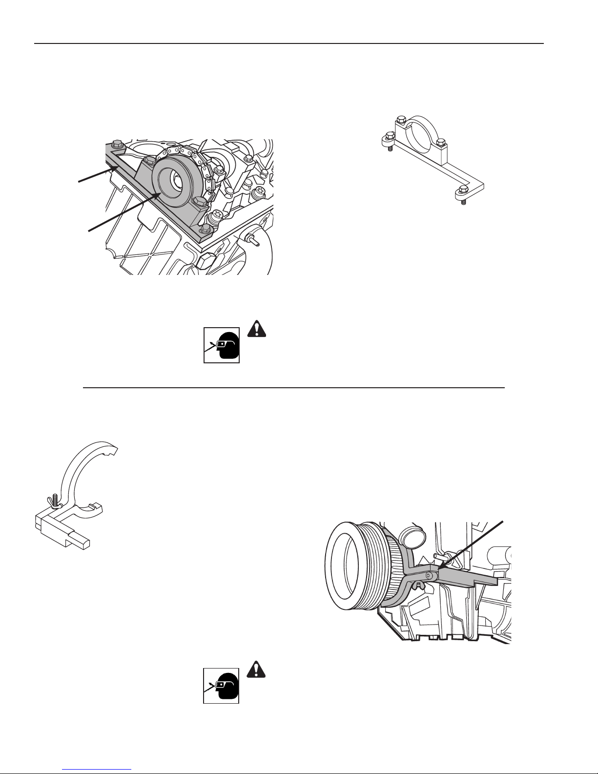
511546 (6478) Ford Camshaft Gear Holding Tool
Application: 1997 – 2011 4.0L SOHC Explorer (V6), Mountaineer (V6), Ranger (VIN E)
1997 – 2008 4.0L SOHC Explorer, Mountaineer, Ranger (VIN X)
2005 – 2010 4.0L SOHC Mustang (VIN N)
No. 511546
(6478)
No. 511550
(6482)
Application: 1997 – 2011 4.0L SOHC Explorer (V6), Mountaineer (V6), Ranger (VIN E)
1. Install tool Nos. 511546 (6478) and 511550 (6482)
on the camshaft as shown.
2. Secure tool No. 511546 (6478) to the cylinder head.
3. Service the timing chain as required according to
instructions in the vehicle service manual.
4. Torque fasteners to factory specications.
WARNING: Wear eye
protection that meets ANSI
Z87.1 and OSHA standards.
511547 (6479) Ford Crankshaft Holding Tool
1997 – 2008 4.0L SOHC Explorer, Mountaineer, Ranger (VIN X)
2005 – 2010 4.0L SOHC Mustang (VIN N)
Note: Same as Ford No. 303-573 (T97T-6303-A).
1. Install tool No. 511547 (6479) on the
crankshaft damper.
2. Rotate the engine counterclockwise (CCW)
until the tool stops against the engine block.
3. Service the timing chain as required
according to instructions in the vehicle
service manual.
4. Torque fasteners to factory specications.
No. 511547
(6479)
WARNING: Wear eye
protection that meets ANSI
Z87.1 and OSHA standards.
Page 16
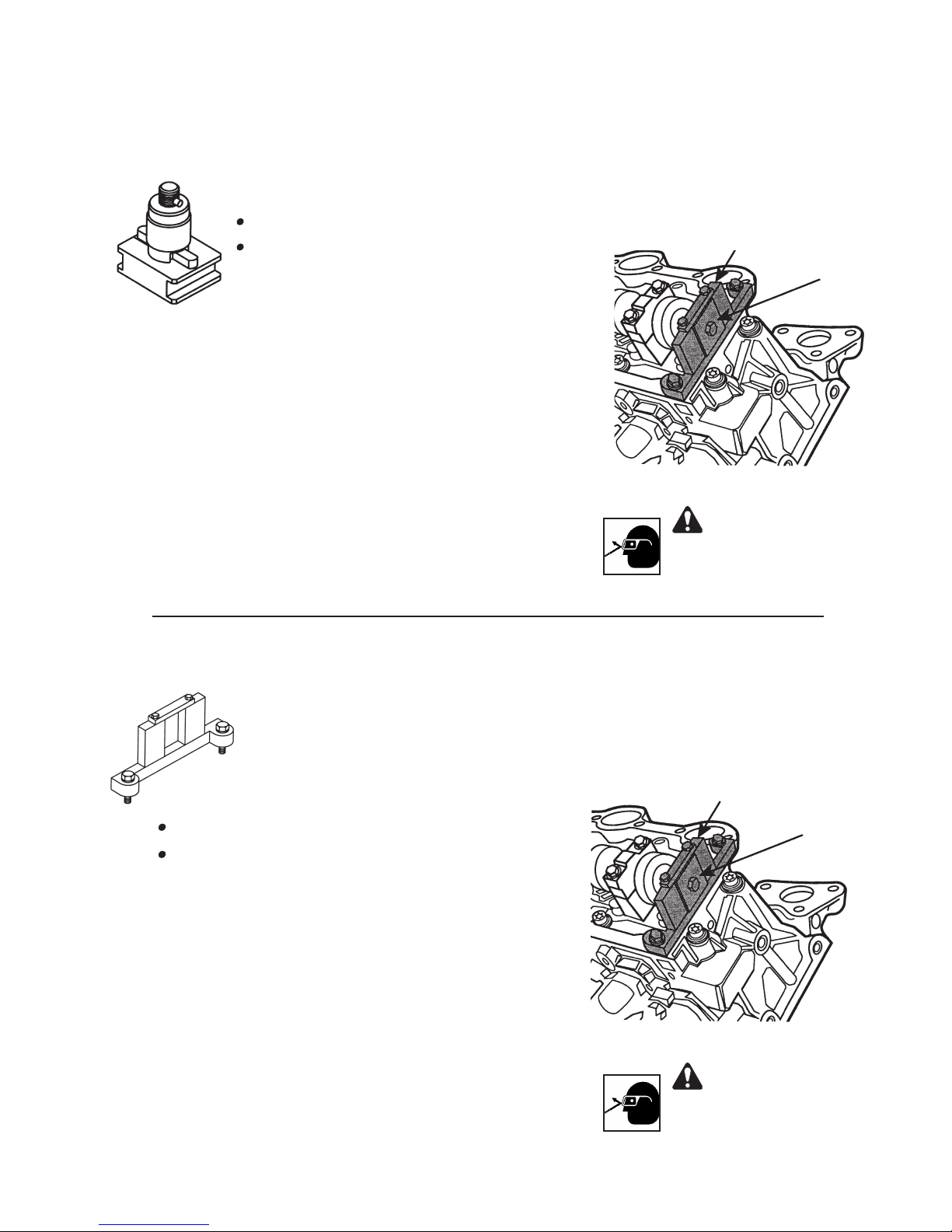
511548 (6480) Ford Camshaft Holding Tool Adapter
Application: 1997 – 2011 4.0L SOHC Explorer (V6), Mountaineer (V6), Ranger (VIN E)
1997 – 2008 4.0L SOHC Explorer, Mountaineer, Ranger (VIN X)
2005 – 2010 4.0L SOHC Mustang (VIN N)
Note:
• Same as Ford No. 303-576 (T97T-6256-D).
• This tool is used with No. 511549 (6481)
Ford Camshaft Holding Tool.
1. Install tool Nos. 511548 (6480) and 511549 (6481) on
the camshaft as shown.
2. Secure tool No. 511549 (6481) to the cylinder head.
3. Service the timing chain as required according to
instructions in the vehicle service manual.
4. Torque fasteners to factory specications.
No. 511549
(6481)
No. 511548
(6480)
WARNING: Wear eye
protection that meets ANSI
Z87.1 and OSHA standards.
511549 (6481) Ford Camshaft Holding Tool
Application: 1997 – 2011 4.0L SOHC Explorer (V6), Mountaineer (V6), Ranger (VIN E)
1997 – 2008 4.0L SOHC Explorer, Mountaineer, Ranger (VIN X)
2005 – 2010 4.0L SOHC Mustang (VIN N)
Note:
• Same as Ford No. 303-577 (T97T-6256-C).
• This tool is used with No. 511548 (6480) Ford
Camshaft Holding Tool Adapter.
1. Install tool Nos. 511548 (6480) and 511549 (6481) on
the camshaft as shown.
2. Secure tool No. 511549 (6481) to the cylinder head.
3. Service the timing chain as required according to
instructions in the vehicle service manual.
4. Torque fasteners to factory specications.
No. 511549
(6481)
No. 511548
(6480)
WARNING: Wear eye
protection that meets ANSI
Z87.1 and OSHA standards.
Page 17
Parts List & Operating Instructions
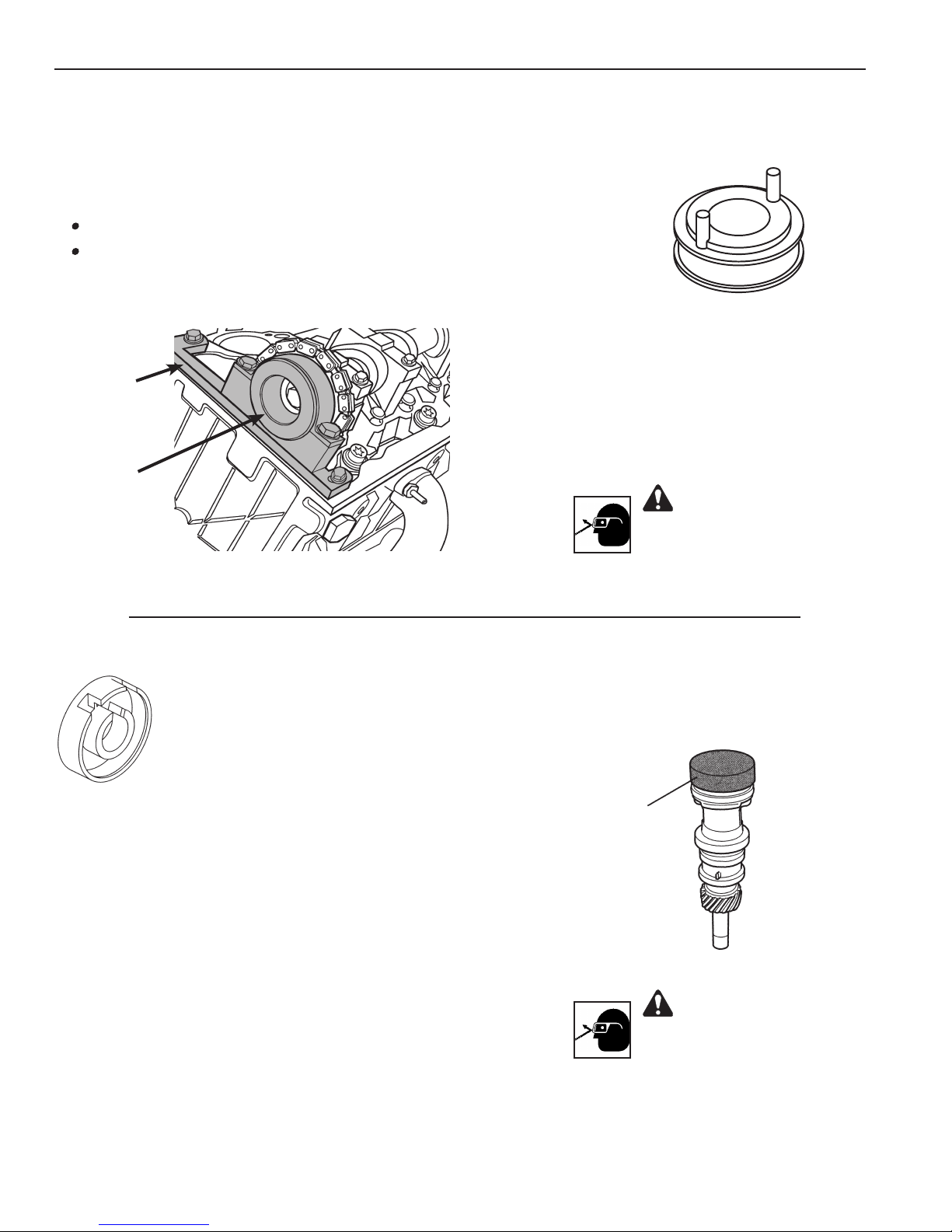
511550 (6482) Ford Camshaft Holding Tool Adapter
Application: 1997 – 2011 4.0L SOHC Explorer (V6), Mountaineer (V6), Ranger (VIN E)
1997 – 2008 4.0L SOHC Explorer, Mountaineer, Ranger (VIN X)
2005 – 2010 4.0L SOHC Mustang (VIN N)
Note:
• Same as Ford No. 303-578 (T97T-6256-A).
• This tool is used with No. 511546 (6478) Ford
Camshaft Gear Holding Tool .
1. Install tool Nos. 511546 (6478) and 511550 (6482)
on the camshaft as shown.
No. 511546
(6478)
No. 511550
(6482)
2. Secure tool No. 511546 (6478) to the cylinder head.
3. Service the timing chain as required according to
instructions in the vehicle service manual.
4. Torque fasteners according to factory specications.
511551 (6483) Ford Camshaft Synchronizer Tool
Application: 1999 – 2002 4.0L Push Rod Explorer, Mountaineer
1999 – 2000 4.0L Push Rod Ranger
Note: Same as Ford No. 303-638.
CAUTION: Before removing the camshaft sensor housing
assembly, note the position of the camshaft sensor electrical
connector. To prevent equipment damage, the connector MUST
be reassembled in the same position during installation.
1. Rotate crankshaft to set No. 1 cylinder at top dead center of
compression stroke.
2. Engage camshaft sensor housing vane in slot of tool No. 511551
(6483).
3. Rotate tool on camshaft sensor housing until tool engages housing
notch. (Tool should be square and in contact with entire top of
housing.)
4. Install camshaft sensor housing and tool assembly into engine
according to instructions in the vehicle service manual.
5. Torque fasteners to factory specications.
No. 511551
(6483)
WARNING: Wear eye
protection that meets ANSI
Z87.1 and OSHA standards.
Camshaft
Sensor
Housing
WARNING: Wear eye
protection that meets ANSI
Z87.1 and OSHA standards.
Page 18
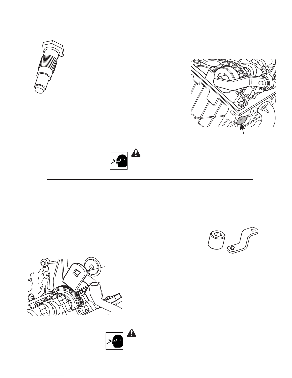
511552 (6484) Ford Timing Chain Tensioner Tool
Application: 1997 – 2011 4.0L SOHC Explorer (V6), Mountaineer (V6), Ranger (VIN E)
1997 – 2008 4.0L SOHC Explorer, Mountaineer, Ranger (VIN X)
2005 – 2010 4.0L SOHC Mustang (VIN N)
Note: Same as Ford No. 303-571 (T97T-6K254-A).
1. Remove the hydraulic chain tensioner from the
engine.
2. Install tool No. 511552 (6484) into the engine to
hold pressure on the timing chain during the cam
timing procedure.
3. Adjust camshaft timing according to instructions
in the vehicle service manual.
4. Torque fasteners to factory specications.
WARNING: Wear eye
protection that meets ANSI
Z87.1 and OSHA standards.
511553 / 511554 (6485) Ford Camshaft
Gear Bolt Socket Extension
Application: 1997 – 2011 4.0L SOHC Explorer (V6), Mountaineer (V6), Ranger (VIN E)
1997 – 2008 4.0L SOHC Explorer, Mountaineer, Ranger (VIN X)
2005 – 2010 4.0L SOHC Mustang (VIN N)
2003 – 2011 4.0L SOHC Ranger
Note: 511553 is the same as Ford No. 303-565 (T97T-6256-G)
and 511554 is the same as Ford No. 303-575 (T97T-6256-F).
No. 6485
(511553 & 511554)
No. 511552
(6484)
No. 511554
Extension
No. 511553
Camshaft Gear
Bolt Socket
1. Assemble the No. 6485 (511553 & 511554) socket and
extension on the camshaft gear bolt as shown.
Removal: Use a ratchet or breaker bar to loosen and remove
the bolt from the camshaft.
Assembly: Use a torque wrench to tighten the bolt on the
camshaft. Refer to the vehicle service manual for the correct
torque specications.
WARNING: Wear eye
protection that meets ANSI
Z87.1 and OSHA standards.
Shop the largest selection of reliable automotive tools in our online store.
 Loading...