

Page 1
655 Eisenhower Drive
Owatonna, MN 55060 USA
Phone: (507) 455-7000
Tech. Serv.: (800) 533-6127
Fax: (800) 955-8329
Order Entry: (800) 533-6127
Fax: (800) 283-8665
International Sales: (507) 455-7223
Fax: (507) 455-7063
Parts List &
Operating Instructions
for:
Form No. 545622
5015A
Heavy-Duty
Clutch Handler
Max. Capacity: 150 lbs.
The OTC Heavy-Duty Clutch Handler and Flywheel Adapter are designed for the removal and installation
of the 14" and 15-1/2" double disc clutches and/or flywheel assemblies found on many heavy-duty vehicles.
Refer to Form No. 105665 for instructions about using the flywheel adapter (OTC No. 218174).
Parts List
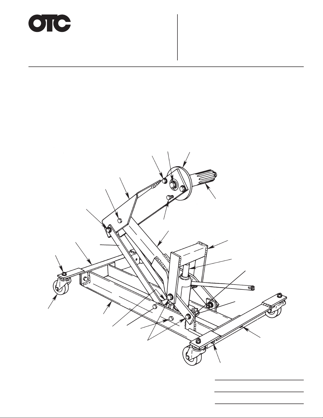
14, 7
17, 18
15
5, 36, 7, 8, 9, 10, 37
3
1, 2
35
6, 11, 12
4
34
32,
33
13
31,
36,
30,
37
36,
30,
37
5,
36,
7,
9,
37
16
5
19
20
21
22, 23, 24
25
26, 27, 28
29, 27, 28
© Bosch Automotive Service Solutions Inc.
Sheet No.
Issue Date: Rev. C, April 3, 2019
1 of 3
Page 2

Parts List & Operating Instructions
Form No. 545622, Sheet 1 of 3, Back
Item
No.
Part
No.
No.
Req'd
Description
1 540573 4 Nut (M12 x 1.75)
2 545602 4 Lockwasher (12 mm)
3 542035 2 Leg Weldment
4 542187 2 Strap
5 540891 7 Cap Screw (.500-13 x 38 mm)
6 540570 1 Locknut
7 541036 8 Plain Washer
8 542617 2 Washer
9 545515 6 Bushing
10 540785 2 Washer
11 542610 1 Cap Screw (.500-13)
12 542184 1 Tube
13 542036 1 Upper Lift Arm Weldment
14 541038 2 Cap Screw (.500-13 x 25.4 mm)
15 542616 1 Plate
16 545765 1 Splined Shaft (2" dia.)
17 542608 1 Cap Screw (.625-11)
18 542613 1 Lockwasher (.625)
19 542034 1 Lower Lift Arm Weldment
20 542027 1 Jack Yoke Weldment
21 600003* 1 Hydraulic Bottle Jack
22 542607 2 Cap Screw (M6-1)
23 542612 2 Nut (M6-1)
24 542614 2 Lockwasher
25 542026 1 Jack Mount Weldment
26 542609 3 Cap Screw (.437-14)
27 542615 4 Lockwasher (.437)
28 542611 5 Nut (.438-14)
29 545518 1 Handle Holder Stud
30 545516 2 Cap Screw (.500-13)
31 12330 2 Washer
32 542185 1 Tube
33 542186 1 Tube
34 542037 1 Cross Frame Weldment
35 540568 4 Swivel Caster
36 10208 8 Nut (.500-13)
37 541030 8 Lockwasher
Parts Included But Not Shown
545621 1 Trade Name/Warning Decal
Optional Accessories
48625 1 Splined Shaft (1-3/4" dia.)
218174 1 Flywheel Adapter (see Form #105665)
* Depending on your model, you may or may not need the extra parts included in this kit.
Refer to any operating instructions included with the product for detailed information about operation,
testing, disassembly, reassembly, and preventive maintenance.
Items found in this parts list have been carefully tested and selected by OTC. Therefore: Use only OTC
replacement parts!
Additional questions can be directed to the OTC Technical Services Department.
Page 3
Parts List & Operating Instructions Form No. 545622
Safety Precautions
CAUTION: To prevent personal injury and/or damage to the equipment,
• Study, understand, and follow all instructions before operating this clutch handler.
• Wear eye protection that meets ANSI Z87.1 and OSHA standards.
• Wear steel-toe shoes that meet ANSI Z41 and OSHA standards.
• If the operator cannot read English, operating instructions and safety precautions
must be read and discussed in the operator’s native language.
– Si el operador no puede leer inglés, las instrucciones de operación y las
precauciones de seguridad deberán leerse y comentarse en el idioma nativo del
operador.
– Si l'utilisateur ne peut lire l'anglais, les instructions et les consignes de sécurité
doivent lui être expliquées dans sa langue maternelle.
• Inspect the clutch handler before each use. Do not use the clutch handler if damaged,
altered, or in poor condition.
• Never exceed the rated lifting capacity of the clutch handler.
• Never move the clutch handler with the load any higher off the ground than necessary.
• Use clutch handler on a hard, level surface.
• Move the clutch handler cautiously around corners to avoid tipping.
• Lowering the lift arm too quickly could cause equipment damage. SLOWLY turn the
hydraulic control valve counterclockwise to release hydraulic pressure.
• Use only those adapters and replacement parts provided by the manufacturer.
• Never modify the unit or adapters.
• Stay clear of the clutch handler’s pinch points as you raise and lower the lift arm.
• Use only approved hydraulic fluid.
Assembly Instructions
(Item numbers refer to the parts list illustration.)
1. Bolt legs (Item #3) to handler using three cap screws (#26),
one threaded handle holder (#29), four washers (#27), and
nuts (#28).
2. Bolt swivel casters (#35) to legs using four washers (#2)
and nuts (#1).
3. Thread two cap screws (#14) through upper lift arm and
tighten.
4. Thread adjusting screw (#5) into upper lift arm.
5. Free up swivel bearing in upper lift arm by applying a
penetrating lubricant to race and working bearing up and
down and side-to-side with a punch or screwdriver.
6. Inser t one cap screw (#17) with washer (#18) through swivel
bearing in upper lift arm. Slide plate (#15) over cap screw.
Thread splined shaft (#16) onto cap screw and tighten.
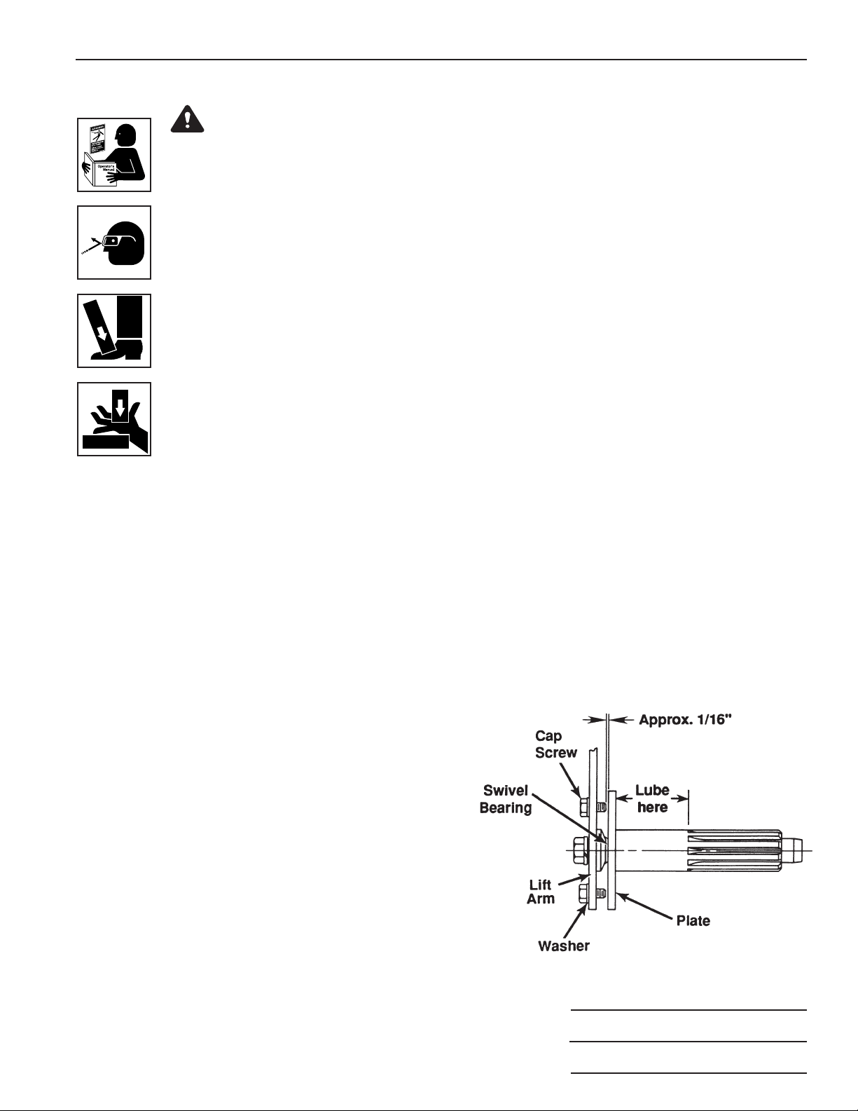
7. Measure distance between plate (#15) and cap screws
(#14). If distance is less than 1/16", remove two cap screws
(#14), and insert a washer (#7) between each cap screw
(#14) and upper lift arm. Wrench tighten. See Figure 1.
Figure 1
Sheet No.
2 of 3
© Bosch Automotive Service Solutions Inc.
Issue Date: Rev. C, April 3, 2019
Page 4
Parts List & Operating Instructions
Operating Instructions
Clutch Removal
1. Attach the correct splined input shaft (2" or the optional 1-3/4" diameter)
to the clutch handler.
2. Sparingly apply lubricant to the area of the splined input shaft shown in
Figure 1.
3. If there isn't enough clearance to roll the clutch handler under the vehicle,
raise the vehicle's front end. Position the clutch handler under the vehicle.
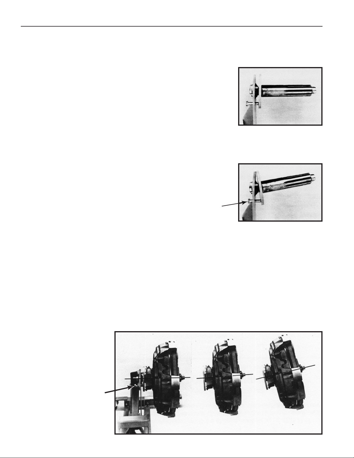
4. Use the adjusting screw to change the angle of the input shaft so it matches
the angle of the vehicle clutch assembly. See Figures 2 and 3.
5. Remove the jack handle from the holder and insert it into the jack. Operate
the jack to raise the upper lift arm to the correct height, and insert the input
shaft into the clutch assembly. Turn the large center cap screw clockwise
to rotate the spline shaft and engage the clutch discs. If necessary, use
the adjusting screw to further improve the alignment of the input shaft. The
splines must completely engage the clutch assembly before you remove
the clutch assembly.
6. Remove the mounting bolts on the pressure plate.
7. Pull the clutch handler and clutch assembly away from the flywheel.
8. Slowly release pressure to lower the clutch assembly to the floor, keeping
clear of the clutch handler's pinch points as it closes.
Adjusting
Screw
Form No. 545622, Sheet 2 of 3, Back
Figure 2
Figure 3
15-1/2" Clutch Installation
1. Sparingly apply lubricant to the area of the input shaft shown in Figure 1.
2. Position the pressure plate, clutch, discs, and spacer onto the clutch handler's input shaft. Important: The input
shaft must pass completely through all components of the clutch assembly.
3. If there isn't enough clearance to roll the clutch handler under the vehicle, raise the vehicle's front end. Position the
clutch handler under the vehicle.
4. Use the adjusting screw to change the angle of the clutch assembly to match the flywheel. See Figure 4.
5. Operate the jack to raise the upper lift arm to the correct height. Roll the clutch handler forward to insert the input
shaft pilot into the flywheel pilot bearing.
6. Bolt the clutch to the flywheel.
7. Slightly release pressure of the upper lift arm. Note: If it is difficult to remove the clutch handler from the clutch
assembly, adjust the alignment of the input shaft by using the adjusting screw.
8. Back the handler away and
slowly release pressure to lower
the upper lift arm to floor level.
Adjusting
Screw
Figure 4
Page 5
Parts List & Operating Instructions Form No. 545622
14" Clutch Installation
1. Sparingly apply lubricant to the area of the input shaft shown in Figure 1.
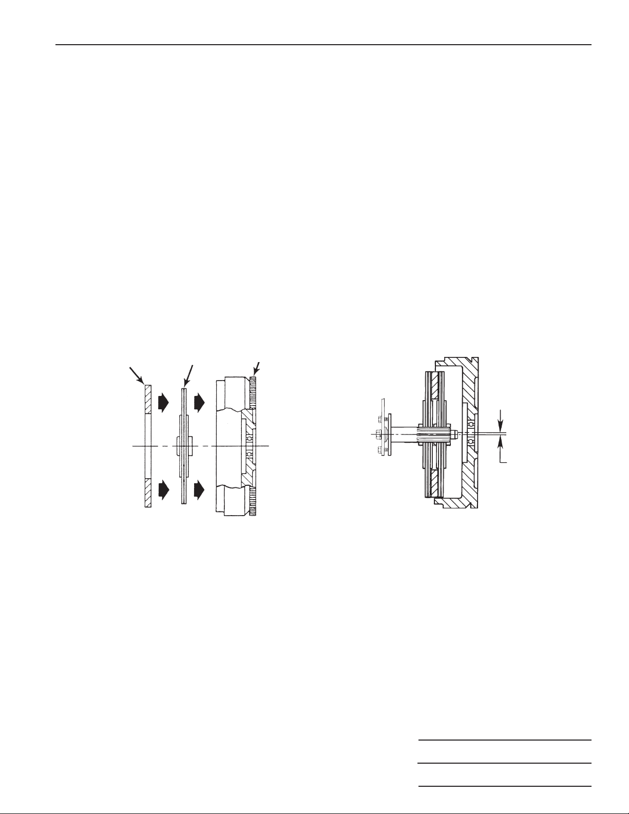
2. Place the new front clutch disc and intermediate plate into the pot type flywheel. See Figure 5.
3. Load the pressure plate and new rear disc on the clutch handler spline shaft.
4. If there isn't enough clearance to roll the clutch handler under the vehicle, raise the vehicle's front end. Position the
clutch handler under the vehicle.
5. Use the adjusting screw to change the angle of the clutch assembly to match the flywheel. See Figure 4.
6. Operate the jack to raise the upper lift arm to the correct height to engage the front disc spline. Roll the clutch handler
forward to insert the spline shaft. Turn the large center cap screw clockwise to rotate the spline shaft for correct
engagement of the clutch disc. Note: The front clutch disc in the flywheel is slightly lower than the center line
of the pilot bearing. It may be necessary to raise the upper lift arm to correctly align the spline shaft with
the pilot bearing. See Figure 6.
7. Bolt the clutch to the flywheel.
8. Slightly release pressure of the upper lift arm. Note: If it is difficult to remove the clutch handler from the clutch
assembly, adjust the alignment of the input shaft by using the adjusting screw.
9. Back the handler away and slowly release pressure to lower the upper lift arm to floor level.
Intermediate
Plate
Front
Disc
Figure 5
Flywheel
Raise lift arm
and clutch
assembly to align
spline shaft with
pilot bearing.
Figure 6
© Bosch Automotive Service Solutions Inc.
Sheet No.
Issue Date: Rev. C, April 3, 2019
3 of 3
 Loading...