

Page 1
Page 2
Explanation of Safety Signal Words
The safety signal word designates the degree or level of hazard seriousness.
DANGER: Indicates an imminently hazardous situation which, if not avoided, will result in death or
serious injury.
WARNING: Indicates a potentially hazardous situation which, if not avoided, could result in death or
serious injury.
CAUTION: Indicates a potentially hazardous situation which, if not avoided, may result in minor or
moderate injury.
CAUTION: Used without the safety alert symbol indicates a potentially hazardous situation which, if not
avoided, may result in property damage.
Page 3
Safety Precautions
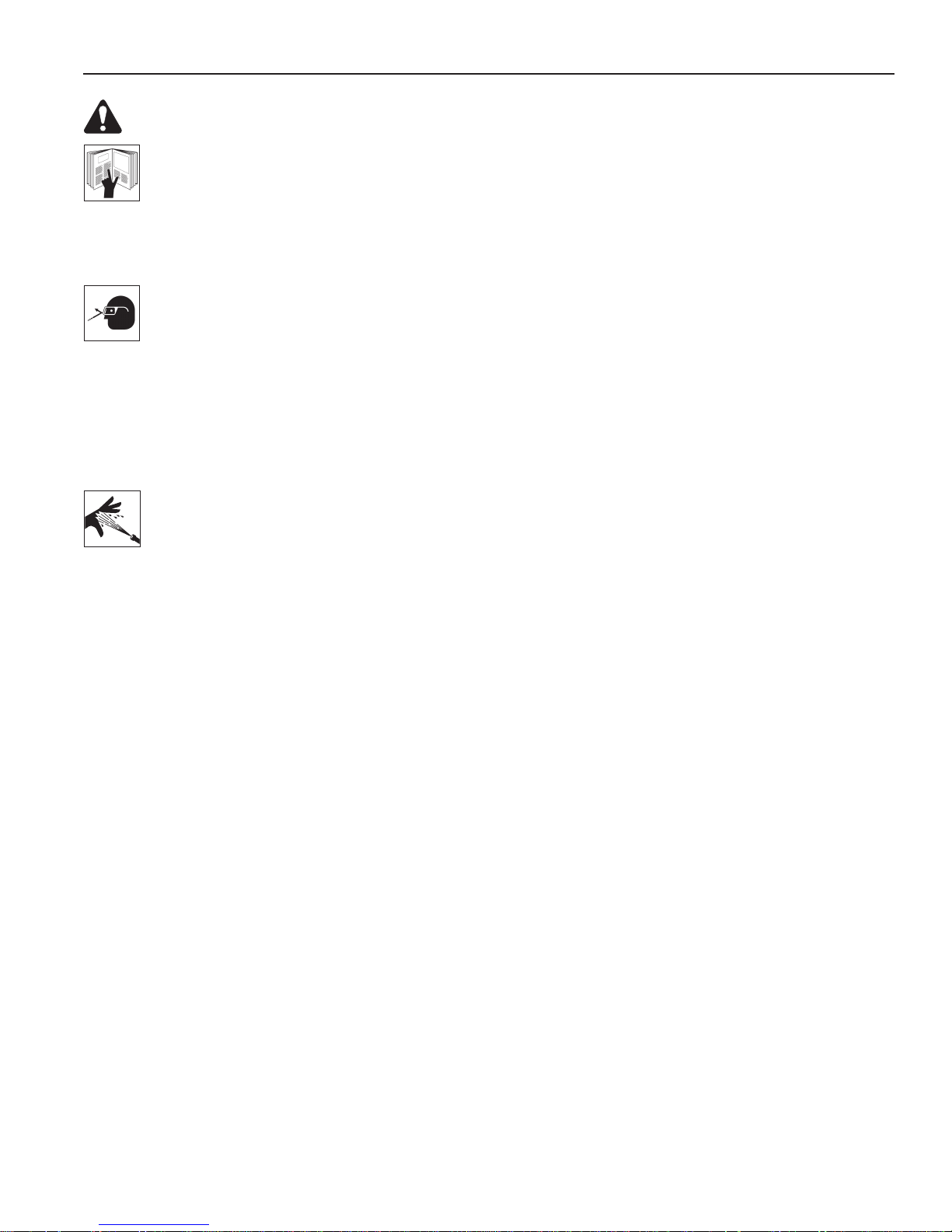
WARNING: To prevent personal injury and/ or property damage,
•
Study, understand, and follow all safety precautions and operating instructions before using
this Hendrickson Rear Suspension Bushing Tool. If the operator cannot read instructions,
operating instructions and safety precautions must be read and discussed in the operator’s
native language.
•
Only qualified operators may install, operate, adjust, maintain, clean, repair, inspect, or
transport this suspension bushing tool.
•
Wear eye protection that meets ANSI Z87.1, CE EN166, AS/NZS 1337, and OSHA standards.
•
Do not use this suspension bushing tool for anything other than its intended purpose.
•
No alteration shall be made to this product.
•
Inspect the condition of the suspension bushing tool before each use; do not use if damaged,
altered, or in poor condition.
•
Use only those repair parts called out in the parts list in this document. Items found in the
parts list have been carefully tested and selected by OTC.
Hose
•
Before operating the pump, tighten all hose connections using the correct tools. Do not
overtighten; connections need only be secure and leak-free. Overtightening can cause
premature thread failure or high pressure fittings to split at pressures lower than their
rated capacities.
•
Should a hydraulic hose ever rupture, burst, or need to be disconnected, immediately shut
OFF the pump, and open the control valve to release all pressure. NEVER grasp a leaking,
pressurized hose with your hands; the force of escaping hydraulic fluid could cause serious
injury.
•
Do not subject the hose to any potential hazard such as fire, extreme cold or heat, sharp
surfaces, or heavy impact. Do not allow the hose to kink, twist, curl, or bend so tightly that
the fluid flow within the hose is blocked or reduced. Do not use the hose to move attached
equipment. Periodically inspect the hose for wear, because any of these conditions can
damage the hose and result in personal injury.
•
Hose material and coupler seals must be compatible with the hydraulic fluid used. Hoses
also must not come in contact with corrosive materials, such as creosote-impregnated
objects and some paints. Consult the manufacturer before painting a hose. Never paint
couplers. Hose deterioration due to corrosive material can result in personal injury.
Pump
•
Do not exceed the maximum capacity of the pump or tamper with the internal high pressure
relief valve. Creating pressure beyond the rated capacity can result in personal injury.
•
Completely retract the cylinder before opening the filler screw on the pump to add hydraulic
fluid. An overfill can cause personal injury due to excess reservoir pressure created when
cylinders are retracted.
Cylinder
•
Do not exceed the maximum capacity of the cylinder. Creating pressure beyond the rated
capacity can result in personal injury.
•
Adapters must be aligned and fully engaged so cylinder force is straight, avoiding an off-
center load condition.
1
Page 4
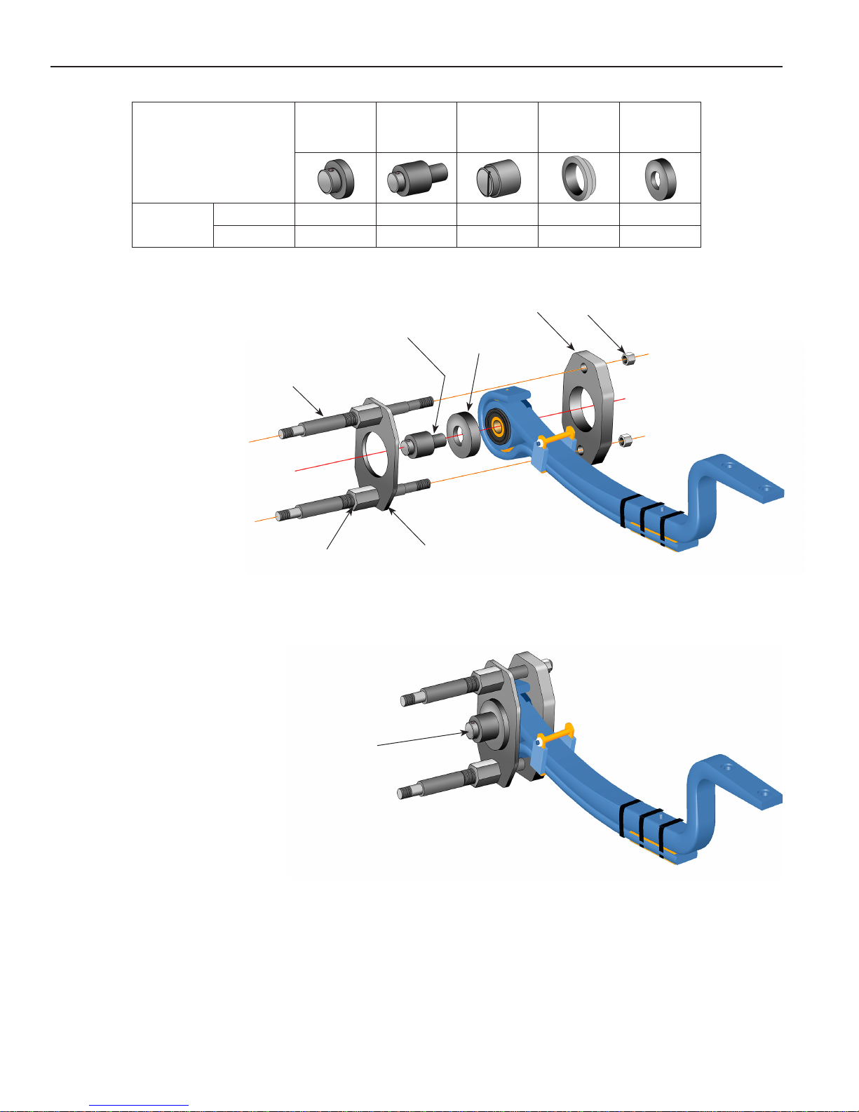
HENDRICKSON COMFORT AIR® – Pivot Bushing Removal
HENDRICKSON
COMFORT AIR
Pivot
Bushing
Pivot Bushing Removal
1.
Insert the adapter pin
through the alignment tool
and into the pivot bushing
hole as shown in Figure 1.
2. Place the clamping plate
over the alignment tool.
3. Assemble the clamping
nuts to the threaded rods.
®
Remove
Install
Threaded
Rod
575164
Saddle
Adapter Pin
575163
Adapter
Pin
4 4 4
4 4
576421
D-Pin
Adapter
Alignment
Tool
Head
Plate
575165
Bushing
Support
Hex
Nut
575167
Alignment
Tool
4. Insert a threaded rod
through the upper holes
in the clamping plate and
the head plate. Install a
hex nut on the threaded
rod, but do not tighten at
this time.
5. Insert a threaded rod
through the lower holes
in the clamping plate and
the head plate. Install a
hex nut on the threaded
rod, but do not tighten at
this time.
6. Tighten the clamping nuts
to the clamping plate. See
Figure 2.
7. Remove the alignment
tool and adapter pin.
Clamping Nut
Remove the
Alignment Tool
and Adapter Pin.
Clamping
Plate
Figure 1
Illustration showing the
assembly after steps 1 – 6.
Figure 2
2
Page 5
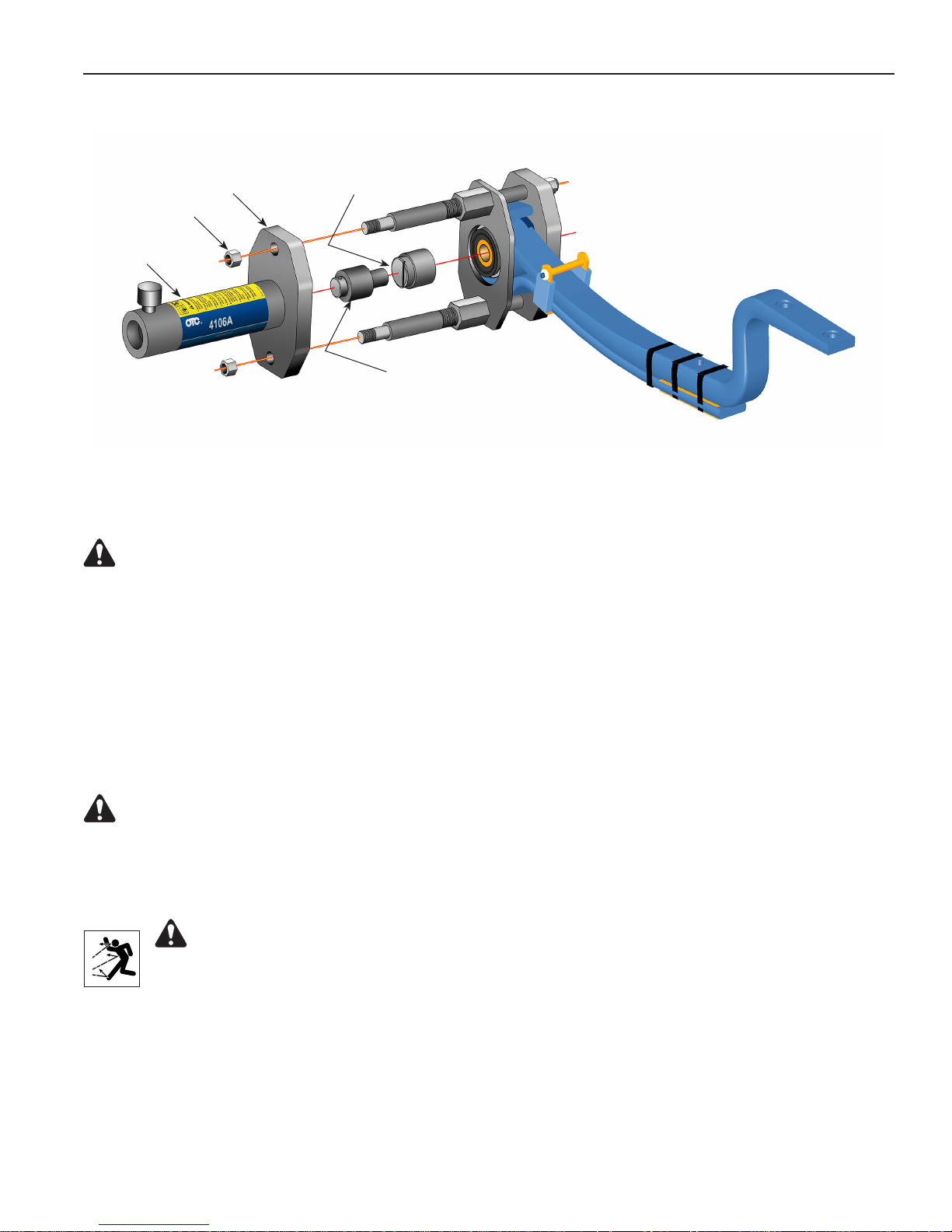
HENDRICKSON COMFORT AIR® – Pivot Bushing Removal
Cylinder
Mounting Plate
Hex Nut
Cylinder
D-Pin
Adapter
Figure 3
Adapter Pin
Pivot Bushing Removal contd.
8. Thread the cylinder into the cylinder mounting plate. See Figure 3.
WARNING: To prevent personal injury, the cylinder must be fully threaded into the cylinder
mounting plate.
9. Install the cylinder mounting plate onto the end of the threaded rods. Adjust the clamping nuts as
needed to fit the threaded rods through the holes in the cylinder mounting plate. Assemble the hex nuts
on the threaded rods. Tighten the hex nuts on both ends of the threaded rods.
10. Hold the D-pin adapter over the pivot bushing until contact is made with the adapter pin.
11. Insert the adapter pin into the head of the cylinder.
12. Prepare the hydraulic pump for use by following the instructions provided with the pump regarding
hookup, venting, priming, and operation.
WARNING: To prevent personal injury, pump capacity must not exceed 10,000 psi.
13. Connect the hydraulic hose from the hydraulic pump to the cylinder.
14. Operate the pump to extend the cylinder piston and apply pressure to push the pivot bushing out of the
beam.
WARNING: To prevent personal injury from possible breakage under pressure, do not
stand in the vicinity of the tool while the pivot bushing is being extracted. It is especially
important to not stand in the direction of the hydraulic force.
3
Page 6
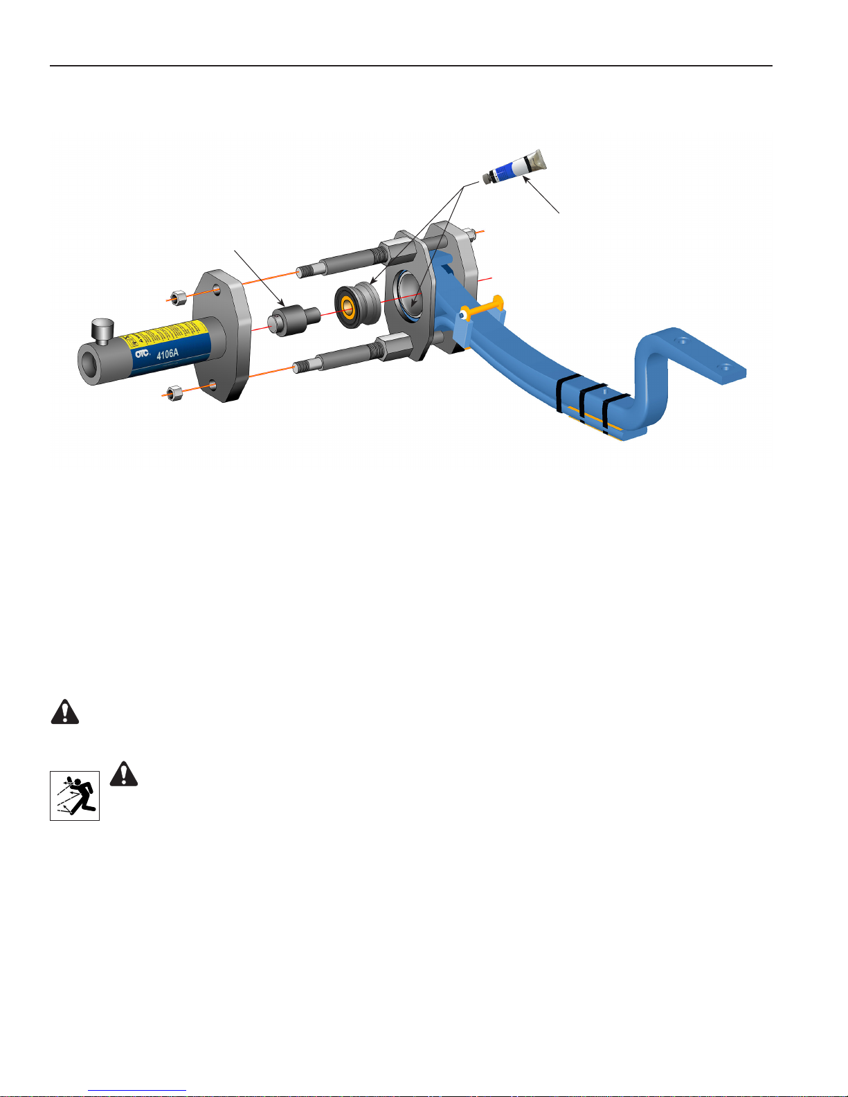
HENDRICKSON COMFORT AIR® – Pivot Bushing Installation
Figure 4
P-80
Adapter Pin
Bushing Lubricant
Pivot Bushing Installation
1. Clean and thoroughly lubricate the entire surface of the inside diameter of the beam and the outer
diameter of the bushing. See Figure 4.
2. Insert the adapter pin into the head of the cylinder.
3. Place the pivot bushing on the end of the adapter pin as shown in Figure 4.
4. Operate the pump to extend the cylinder piston and apply enough pressure to hold the tool and
components. Check the alignment of the pivot bushing.
WARNING: To prevent personal injury, pump capacity must not exceed 10,000 psi.
5. Operate the pump to apply pressure to install the pivot bushing completely into the beam.
WARNING: To prevent personal injury from possible breakage under pressure, do not
stand in the vicinity of the tool while the pivot bushing is being installed. It is especially
important to not stand in the direction of the hydraulic force.
4
Page 7
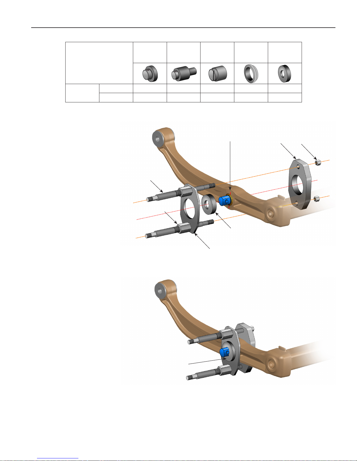
HENDRICKSON PRIMAAX® EX – D-Pin Removal
PRIMAAX® EX
D-Pin
(52K or 46K)
Remove
Install
D-Pin Removal
1. Mark the beam to show the
alignment of the existing
D-pin. Install the alignment
tool over the D-pin, and
place the clamping plate
over the alignment tool. See
Figure 5.
2. Assemble the clamping nuts
to the threaded rods.
575164
Saddle
4 4 4
Threaded Rod
Clamping Nut
575163
Adapter
Pin
4 4 4
576421
D-Pin
Adapter
Mark the
alignment of
the D-pin.
575165
Bushing
Support
575167
Alignment
Tool
Head
Plate
Hex
Nut
3. Insert a threaded rod
through the upper holes in
the clamping plate and the
head plate. Install a hex nut
on the threaded rod, but do
not tighten at this time.
4. Insert a threaded rod
through the lower holes in
the clamping plate and the
head plate. Install a hex nut
on the threaded rod, but do
not tighten at this time.
5. Tighten the clamping nuts
to the clamping plate. See
Figure 6.
6. Remove the alignment tool.
Alignment
Tool
Figure 5
Clamping
Plate
Illustration showing the
assembly after steps 1 – 5.
Remove the
Alignment Tool.
Figure 6
5
Page 8
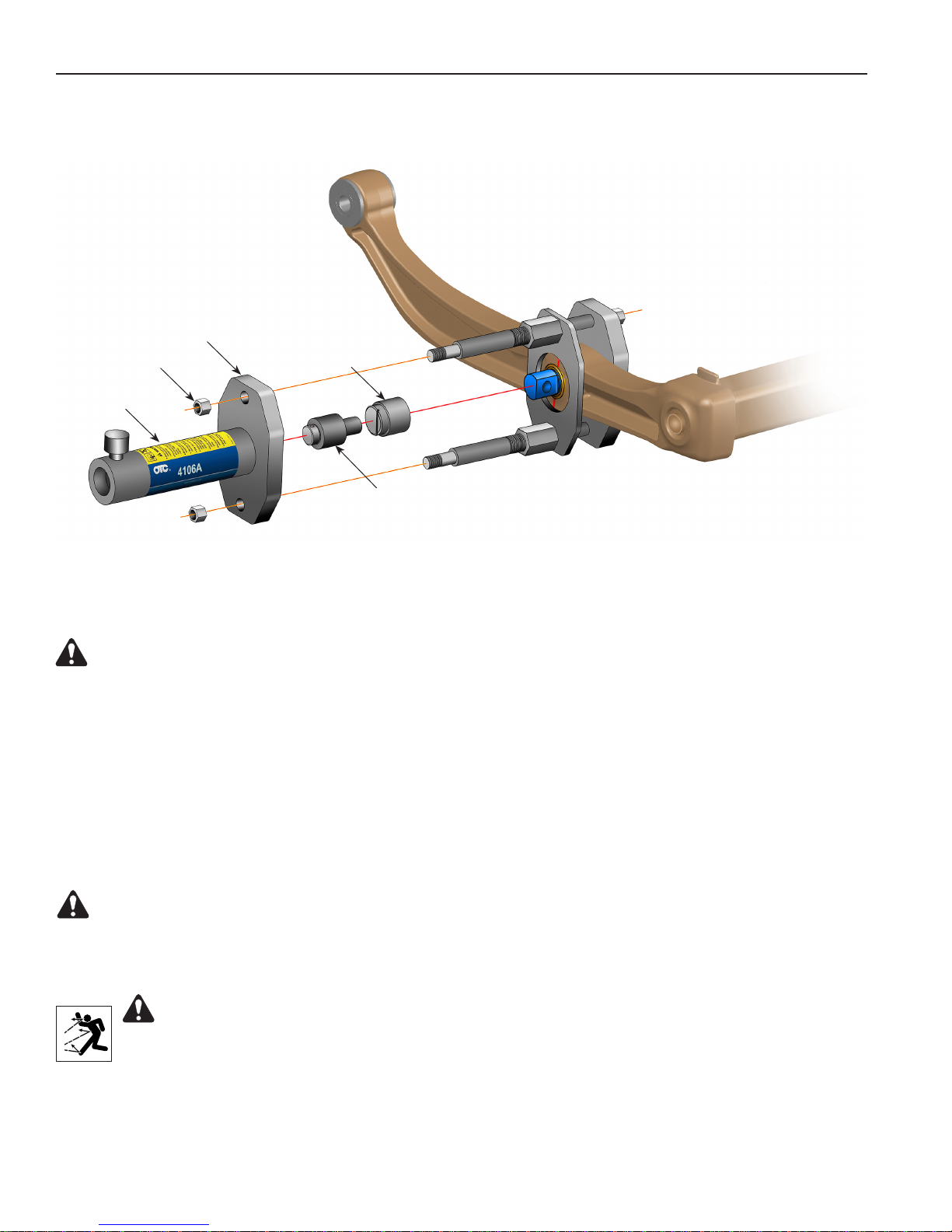
Hex Nut
Cylinder
HENDRICKSON PRIMAAX® EX – D-Pin Removal
Cylinder
Mounting Plate
D-Pin
Adapter
Adapter Pin
Figure 7
D-Pin Removal contd.
7. Thread the cylinder into the cylinder mounting plate. See Figure 7.
WARNING: To prevent personal injury, the cylinder must be fully threaded into the cylinder
mounting plate.
8. Install the cylinder mounting plate onto the end of the threaded rods. Adjust the clamping nuts as
needed to fit the threaded rods through the holes in the cylinder mounting plate. Assemble the hex nuts
on the threaded rods. Tighten the hex nuts on both ends of the threaded rods.
9. Place the D-pin adapter over the D-pin.
10. Insert the adapter pin into the head of the cylinder.
11. Prepare the hydraulic pump for use by following the instructions provided with the pump regarding
hookup, venting, priming, and operation.
WARNING: To prevent personal injury, pump capacity must not exceed 10,000 psi.
12. Connect the hydraulic hose from the hydraulic pump to the cylinder.
13. Operate the pump to extend the cylinder piston and apply pressure to push the D-pin out of the beam.
WARNING: To prevent personal injury from possible breakage under pressure, do not
stand in the vicinity of the tool while the D-pin is being extracted. It is especially important
to not stand in the direction of the hydraulic force.
6
Page 9
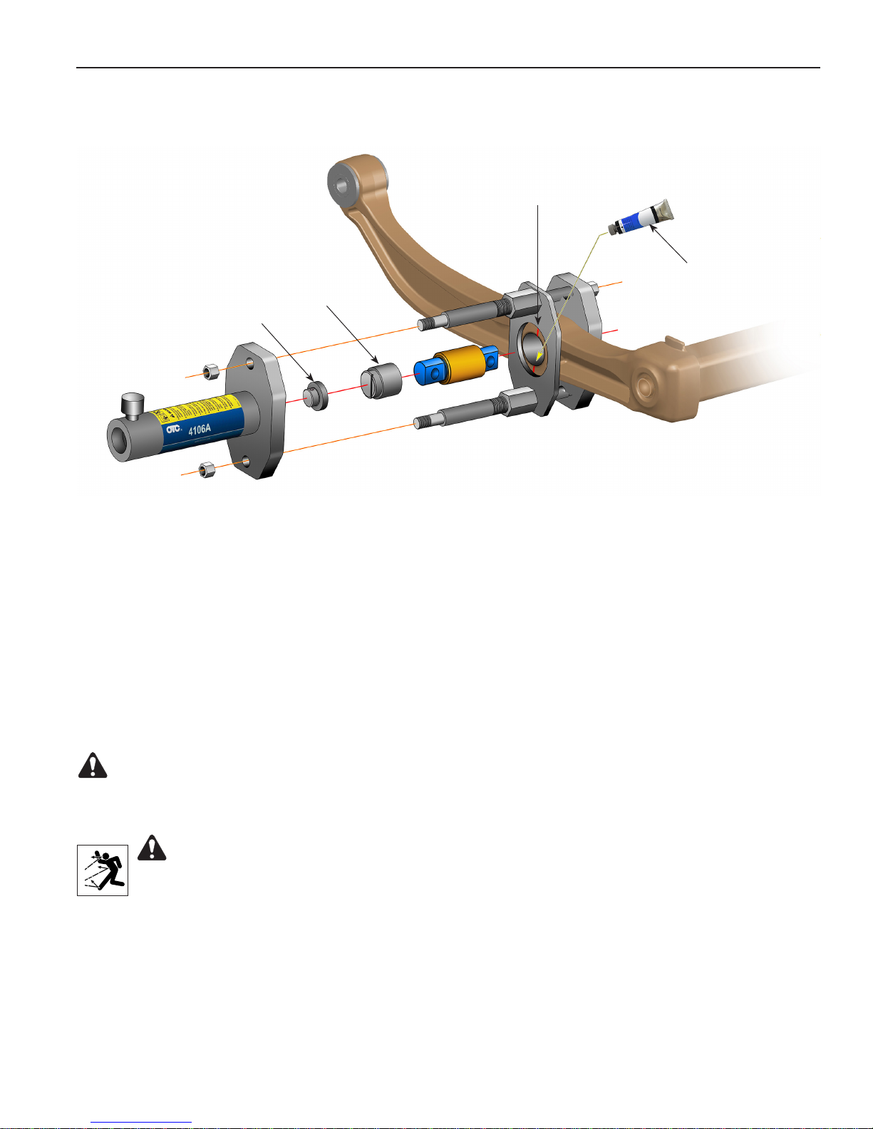
HENDRICKSON PRIMAAX® EX – D-Pin Installation
Align D-pin with
marks made
during removal.
D-pin
Adapter
Saddle
Lubricant with
chassis grease
(NLGI #2)
Figure 8
D-Pin Installation
1. Clean and thoroughly lubricate the entire surface of the inside diameter of the beam and outer bushing.
See Figure 8.
2. Insert the saddle into the head of the cylinder.
3. Assemble the new D-pin and the D-pin adapter as shown. Align the line in the D-pin adapter with the
alignment marks made during the removal procedure.
4. Operate the pump to extend the cylinder piston and apply enough pressure to hold the tool and
components. Check the alignment of the D-pin. The centerline of the D-pin must be aligned with the
centerline of the inside diameter of the beam.
WARNING: To prevent personal injury, pump capacity must not exceed 10,000 psi.
5. Operate the pump to apply pressure to install the D-pin completely into the beam. Confirm the D-pin is
centered in the beam.
WARNING: To prevent personal injury from possible breakage under pressure, do not
stand in the vicinity of the tool while the D-pin is being installed. It is especially important to
not stand in the direction of the hydraulic force.
7
Page 10
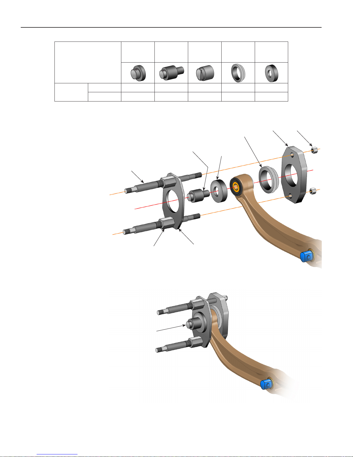
HENDRICKSON PRIMAAX® EX – Pivot Bushing Removal
HENDRICKSON
PRIMAAX® EX
Pivot
Bushing
Pivot Bushing Removal
1. Insert the adapter pin
through the alignment
tool and into the pivot
bushing hole as shown
in Figure 9.
2. Insert the bushing
support over the pivot
bushing.
Remove
Install
575164
Saddle
Threaded Rod
575163
Adapter
Pin
4 4 4 4
4 4 4
Adapter Pin
576421
D-Pin
Adapter
Alignment
575165
Bushing
Support
Bushing
Support
Tool
575167
Alignment
Tool
Head
Plate
Hex
Nut
3. Assemble the clamping
nuts to the threaded
rods.
4. Insert a threaded rod
through the upper holes
in the clamping plate
and the head plate while
positioning the head
plate over the bushing
support. Install a hex
nut on the threaded rod,
but do not tighten at this
time.
5. Insert a threaded rod
through the lower holes
in the clamping plate
and the head plate.
Install a hex nut on the
threaded rod, but do not
tighten at this time.
Clamping Nut
Remove the
Alignment Tool
and Adapter Pin.
Figure 9
Clamping
Plate
Illustration showing the
assembly after steps 1 – 6.
Figure 10
6. Tighten the clamping
nuts to the clamping
plate. See Figure 10.
7. Remove the alignment
tool and adapter pin.
8
Page 11
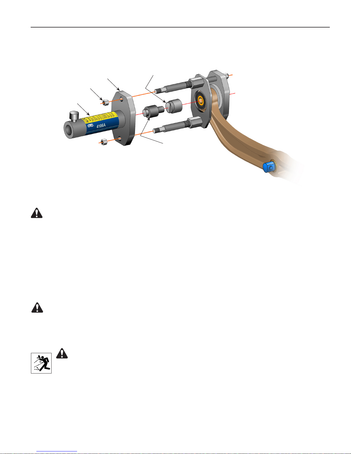
HENDRICKSON PRIMAAX® EX – Pivot Bushing Removal
Cylinder
Mounting Plate
Hex Nut
Cylinder
D-Pin
Adapter
Figure 11
Adapter Pin
Pivot Bushing Removal contd.
8. Thread the cylinder into the cylinder mounting plate. See Figure 11.
WARNING: To prevent personal injury, the cylinder must be fully threaded into the cylinder
mounting plate.
9. Install the cylinder mounting plate onto the end of the threaded rods. Adjust the clamping nuts as
needed to fit the threaded rods through the holes in the cylinder mounting plate. Assemble the hex nuts
on the threaded rods. Tighten the hex nuts on both ends of the threaded rods.
10. Hold the D-pin adapter over the pivot bushing until contact is made with the adapter pin.
11. Insert the adapter pin into the head of the cylinder.
12. Prepare the hydraulic pump for use by following the instructions provided with the pump regarding
hookup, venting, priming, and operation.
WARNING: To prevent personal injury, pump capacity must not exceed 10,000 psi.
13. Connect the hydraulic hose from the hydraulic pump to the cylinder.
14. Operate the pump to extend the cylinder piston and apply pressure to push the pivot bushing out of the
beam.
WARNING: To prevent personal injury from possible breakage under pressure, do not
stand in the vicinity of the tool while the pivot bushing is being extracted. It is especially
important to not stand in the direction of the hydraulic force.
9
Page 12
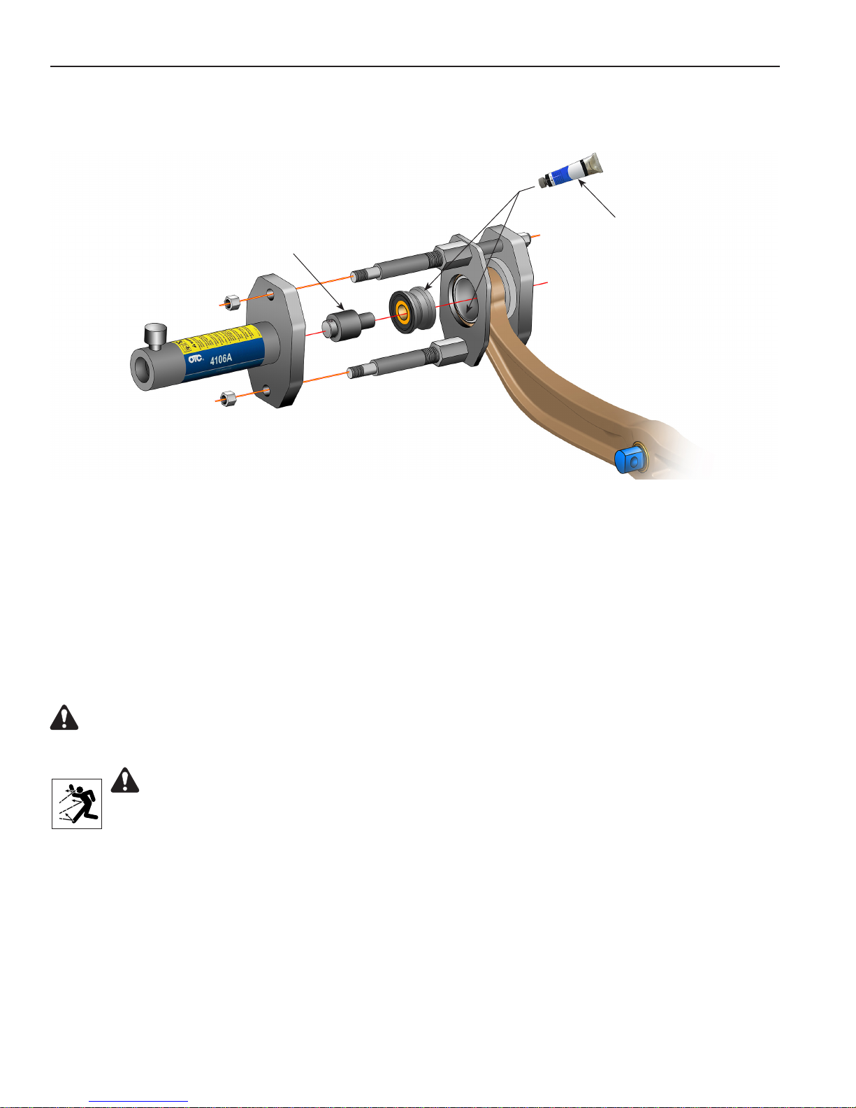
HENDRICKSON PRIMAAX® EX – Pivot Bushing Installation
Figure 12
P-80
Adapter Pin
Bushing Lubricant
Pivot Bushing Installation
1. Clean and thoroughly lubricate the entire surface of the inside diameter of the beam and the outer
diameter of the bushing. See Figure 12.
2. Insert the adapter pin into the head of the cylinder.
3. Place the pivot bushing on the end of the adapter pin as shown.
4. Operate the pump to extend the cylinder piston and apply enough pressure to hold the tool and
components. Check the alignment of the pivot bushing.
WARNING: To prevent personal injury, pump capacity must not exceed 10,000 psi.
5. Operate the pump to apply pressure to install the pivot bushing completely into the beam.
WARNING: To prevent personal injury from possible breakage under pressure, do not
stand in the vicinity of the tool while the pivot bushing is being installed. It is especially
important to not stand in the direction of the hydraulic force.
10
Page 13
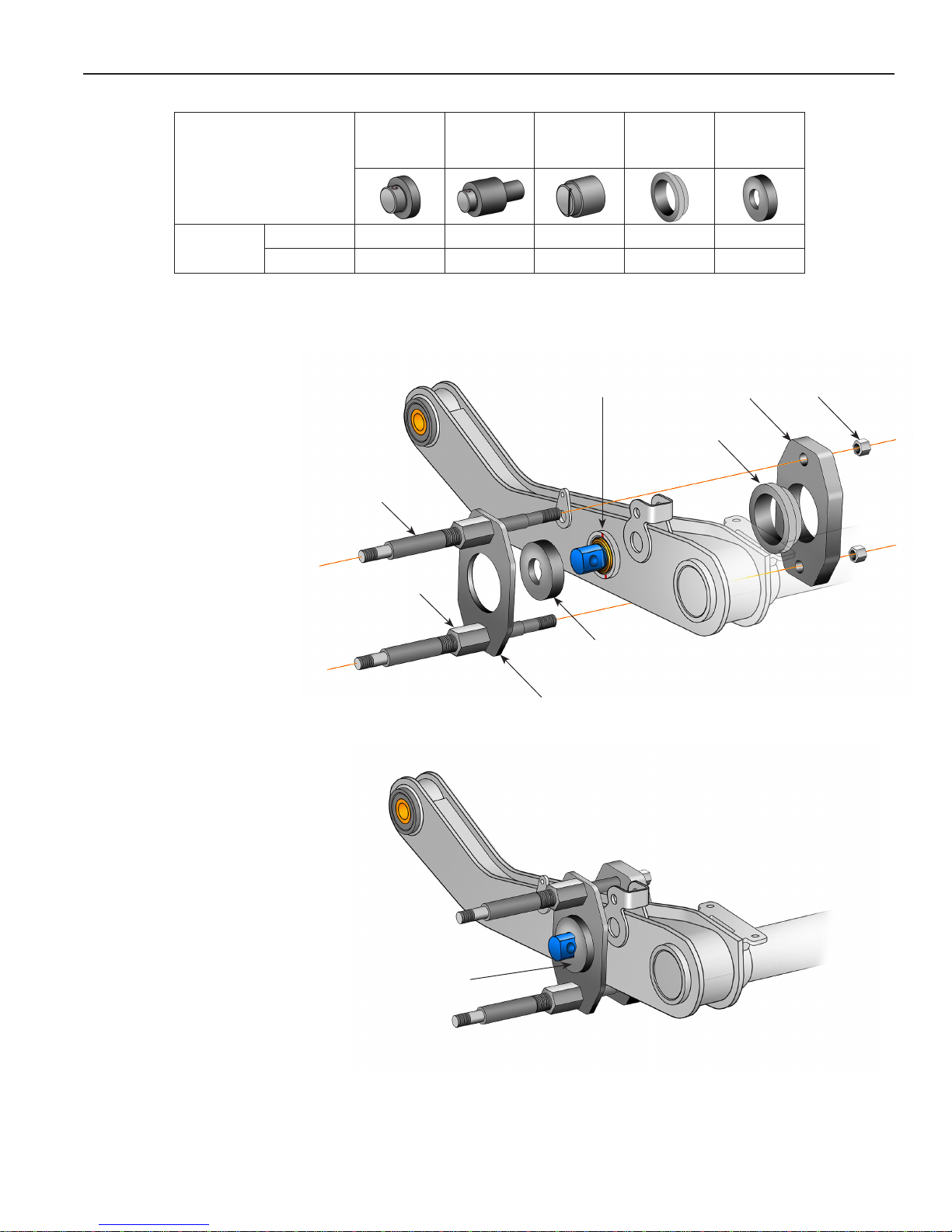
FCCC V-RIDE™– D-Pin Removal
FCCC V-Ride™
D-Pin
(52K or 46K)
D-Pin Removal
1. Mark the beam to show
the alignment of the
existing D-pin. Install
the alignment tool over
the D-pin, and place the
clamping plate over the
alignment tool. See
Figure 13.
2. Insert the bushing
support into the head
plate.
Remove
Install
575164
Saddle
4 4 4 4
Threaded Rod
Clamping Nut
575163
Adapter
Pin
4 4 4 4
576421
D-Pin
Adapter
Mark the
alignment of
the D-pin.
575165
Bushing
Support
Bushing
Support
575167
Alignment
Tool
Head
Plate
Hex
Nut
3. Assemble the clamping
nuts to the threaded
rods.
4. Insert a threaded rod
through the upper holes
in the clamping plate
and the head plate.
Install a hex nut on the
threaded rod, but do not
tighten at this time.
5. Insert a threaded rod
through the lower holes
in the clamping plate
and the head plate.
Install a hex nut on the
threaded rod, but do not
tighten at this time.
6. Tighten the clamping
nuts to the clamping
plate. See Figure 14.
Remove the
Alignment Tool.
Clamping
Plate
Alignment
Tool
Figure 13
Illustration showing the
assembly after steps 1 – 6.
Figure 14
7. Remove the alignment
tool.
11
Page 14
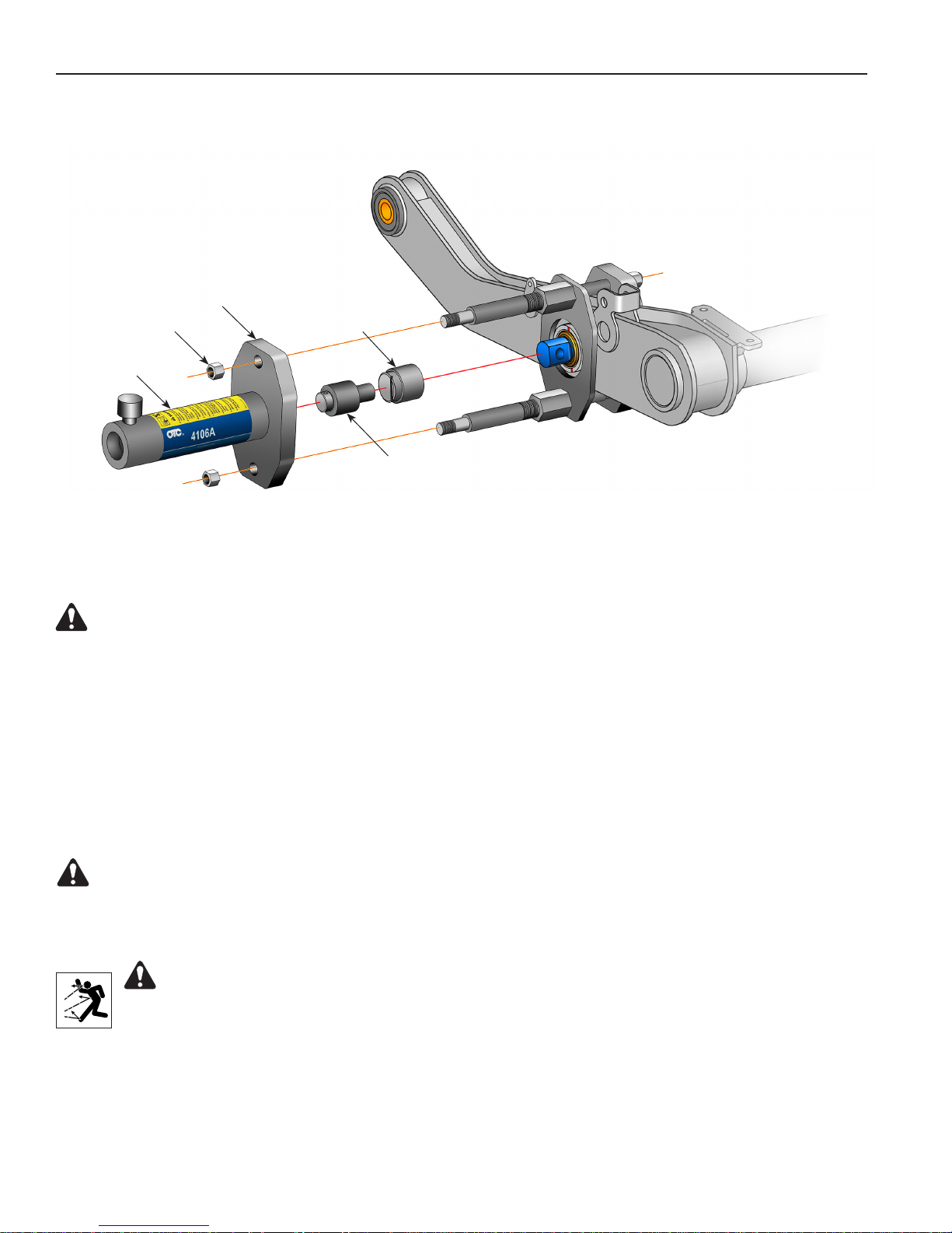
Hex Nut
Cylinder
FCCC V-RIDE™– D-Pin Removal
Cylinder
Mounting Plate
D-Pin
Adapter
Adapter Pin
Figure 15
D-Pin Removal contd.
8. Thread the cylinder into the cylinder mounting plate. See Figure 15.
WARNING: To prevent personal injury, the cylinder must be fully threaded into the cylinder
mounting plate.
9. Install the cylinder mounting plate onto the end of the threaded rods. Adjust the clamping nuts as
needed to fit the threaded rods through the holes in the cylinder mounting plate. Assemble the hex nuts
on the threaded rods. Tighten the hex nuts on both ends of the threaded rods.
10. Place the D-pin adapter over the D-pin.
11. Inser t the adapter pin into the head of the cylinder.
12. Prepare the hydraulic pump for use by following the instructions provided with the pump regarding
hookup, venting, priming, and operation.
WARNING: To prevent personal injury, pump capacity must not exceed 10,000 psi.
13. Connect the hydraulic hose from the hydraulic pump to the cylinder.
14. Operate the pump to extend the cylinder piston and apply pressure to push the D-pin out of the beam.
WARNING: To prevent personal injury from possible breakage under pressure, do not
stand in the vicinity of the tool while the D-pin is being extracted. It is especially important
to not stand in the direction of the hydraulic force.
12
Page 15
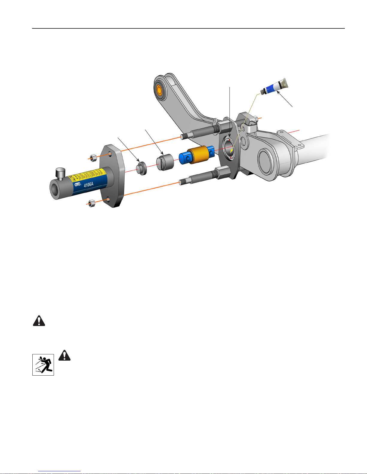
FCCC V-RIDE™– D-Pin Installation
Align D-pin with
marks made
during removal.
D-pin
Adapter
Saddle
Lubricant with
chassis grease
(NLGI #2)
Figure 16
D-Pin Installation
1. Clean and thoroughly lubricate the entire surface of the inside diameter of the beam and outer bushing.
See Figure 16.
2. Insert the saddle into the head of the cylinder.
3. Assemble the new D-pin and the D-pin adapter as shown. Align the line in the D-pin adapter with the
alignment marks made during the removal procedure.
4. Operate the pump to extend the cylinder piston and apply enough pressure to hold the tool and
components. Check the alignment of the D-pin. The centerline of the D-pin must be aligned with the
centerline of the inside diameter of the beam.
WARNING: To prevent personal injury, pump capacity must not exceed 10,000 psi.
5. Operate the pump to apply pressure to install the D-Pin completely into the beam. Confirm the D-pin is
centered in the beam.
WARNING: To prevent personal injury from possible breakage under pressure, do not
stand in the vicinity of the tool while the D-pin is being installed. It is especially important to
not stand in the direction of the hydraulic force.
13
Page 16
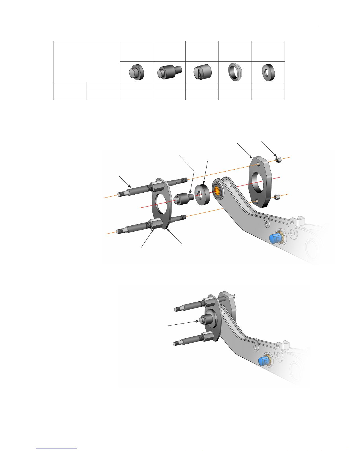
FCCC V-RIDE™– Pivot Bushing Removal
FCCC V-Ride™
Pivot
Bushing
Pivot Bushing Removal
1. Insert the adapter pin
through the alignment
tool and into the pivot
bushing hole as shown
in Figure 17.
2. Assemble the clamping
nuts to the threaded
rods.
Remove
Install
Threaded
Rod
575164
Saddle
575163
Adapter
Pin
4 4 4
4 4
Adapter Pin
576421
D-Pin
Adapter
Alignment
Tool
575165
Bushing
Support
Head
Plate
575167
Alignment
Tool
Hex
Nut
3. Insert a threaded rod
through the upper holes
in the clamping plate
and the head plate.
Install a hex nut on the
threaded rod, but do not
tighten at this time.
4. Insert a threaded rod
through the lower holes
in the clamping plate
and the head plate.
Install a hex nut on the
threaded rod, but do not
tighten at this time.
5. Tighten the clamping
nuts to the clamping
plate. See Figure 18.
6. Remove the alignment
tool and adapter pin.
Clamping
Nut
Remove the
Alignment Tool
and Adapter Pin.
Clamping
Plate
Figure 17
Illustration showing the
assembly after steps 1 – 5.
14
Figure 18
Page 17
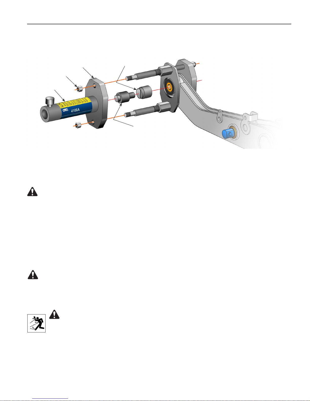
FCCC V-RIDE™– Pivot Bushing Removal
Cylinder
Mounting Plate
Hex Nut
Cylinder
D-Pin
Adapter
Figure 19
Adapter Pin
Pivot Bushing Removal contd.
7. Thread the cylinder into the cylinder mounting plate. See Figure 19.
WARNING: To prevent personal injury, the cylinder must be fully threaded into the cylinder
mounting plate.
8. Install the cylinder mounting plate onto the end of the threaded rods. Adjust the clamping nuts as
needed to fit the threaded rods through the holes in the cylinder mounting plate. Assemble the hex nuts
on the threaded rods. Tighten the hex nuts on both ends of the threaded rods.
9. Hold the D-pin adapter over the pivot bushing until contact is made with the adapter pin.
10. Insert the adapter pin into the head of the cylinder.
11. Prepare the hydraulic pump for use by following the instructions provided with the pump regarding
hookup, venting, priming, and operation.
WARNING: To prevent personal injury, pump capacity must not exceed 10,000 psi.
12. Connect the hydraulic hose from the hydraulic pump to the cylinder.
13. Operate the pump to extend the cylinder piston and apply pressure to push the pivot bushing out of the
beam.
WARNING: To prevent personal injury from possible breakage under pressure, do not
stand in the vicinity of the tool while the pivot bushing is being extracted. It is especially
important to not stand in the direction of the hydraulic force.
15
Page 18
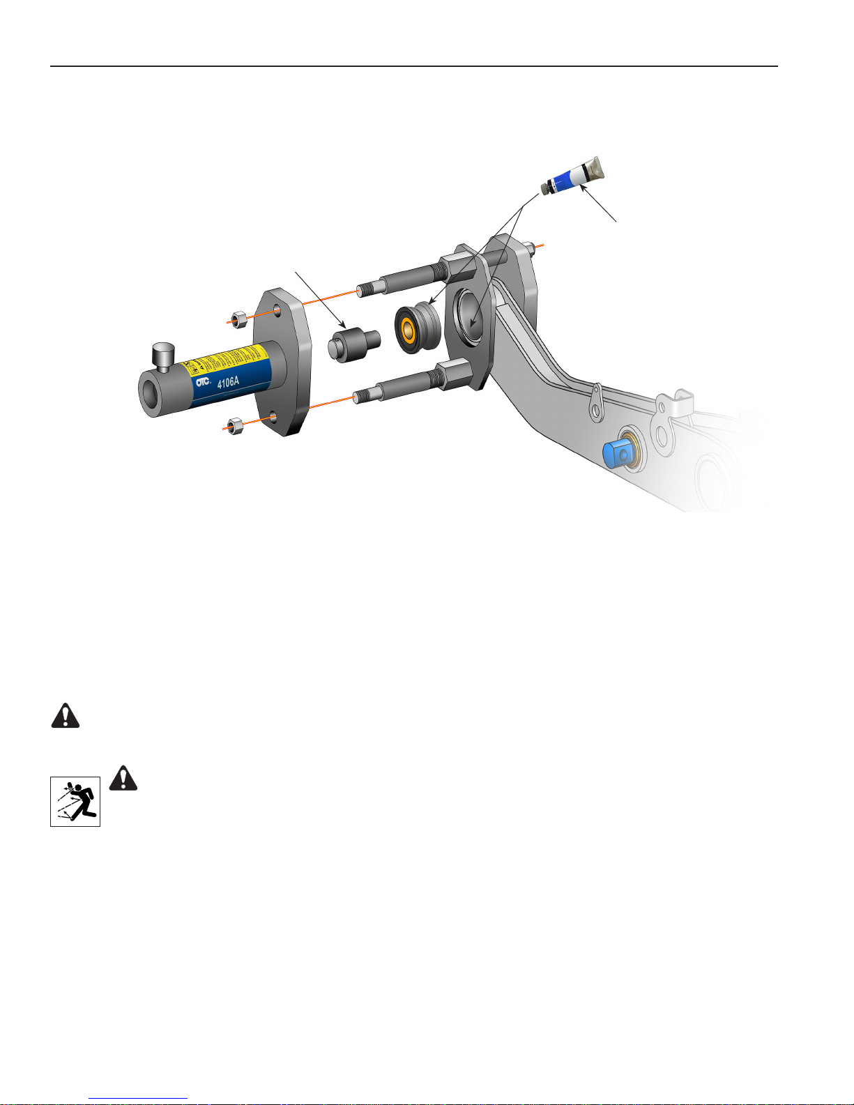
FCCC V-RIDE™– Pivot Bushing Installation
Figure 20
P-80
Bushing Lubricant
Adapter Pin
Pivot Bushing Installation
1. Clean and thoroughly lubricate the entire surface of the inside diameter of the beam and outer diameter
of the bushing. See Figure 20.
2. Insert the adapter pin into the head of the cylinder.
3. Place the pivot bushing on the end of the adapter pin as shown.
4. Operate the pump to extend the cylinder piston and apply enough pressure to hold the tool and
components. Check the alignment of the pivot bushing.
WARNING: To prevent personal injury, pump capacity must not exceed 10,000 psi.
5. Operate the pump to apply pressure to install the pivot bushing completely into the beam.
WARNING: To prevent personal injury from possible breakage under pressure, do not
stand in the vicinity of the tool while the pivot bushing is being installed. It is especially
important to not stand in the direction of the hydraulic force.
16
Page 19
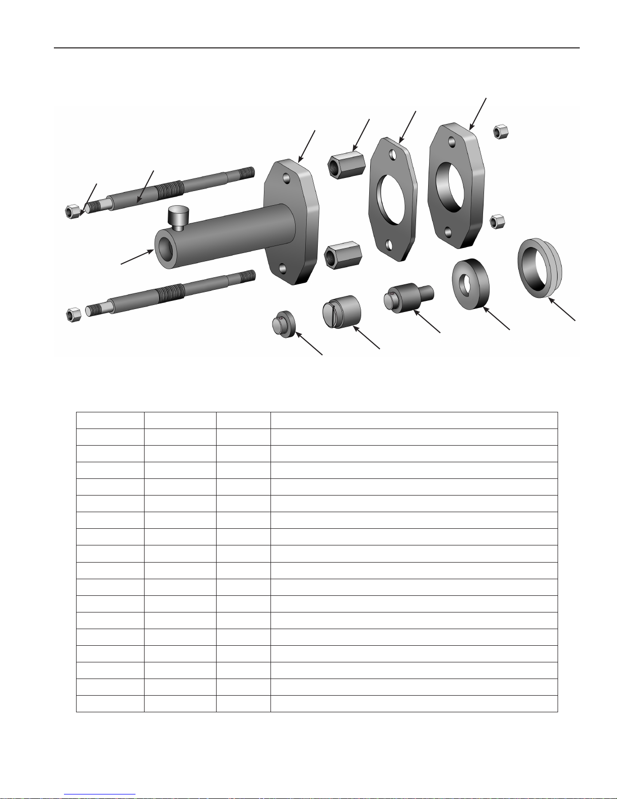
Parts List
6
4
3
2
1
7
5
8
9
Item No. Part No. Qty. Description
1
2
3
4
5
6
7
8
9
10
11
12
576924
575170
575173
575169
575171
575172
4106A
575164
576421
575163
575167
575165
575166
104031
36886
2510A
9798
1 Hex Nut Kit (contains four nuts)
2 Threaded Rod
1 Cylinder Mounting Plate
2 Clamping Nut
1 Clamping Plate
1 Head Plate
1 Hydraulic Cylinder (25 Ton)
1 Saddle
1 D-Pin Adapter
1 Adapter Pin
1 Alignment Tool
1 Bushing Support
1 Warning Decal (not shown)
1 Warranty / Authorized Service Center List (not shown)
1 Hose Assembly (4247 only; not shown)
1 Air / Hydraulic Pump (4247 only; not shown)
1 Hose Half Coupler (4247 only; not shown)
10
11
12
17
Page 20
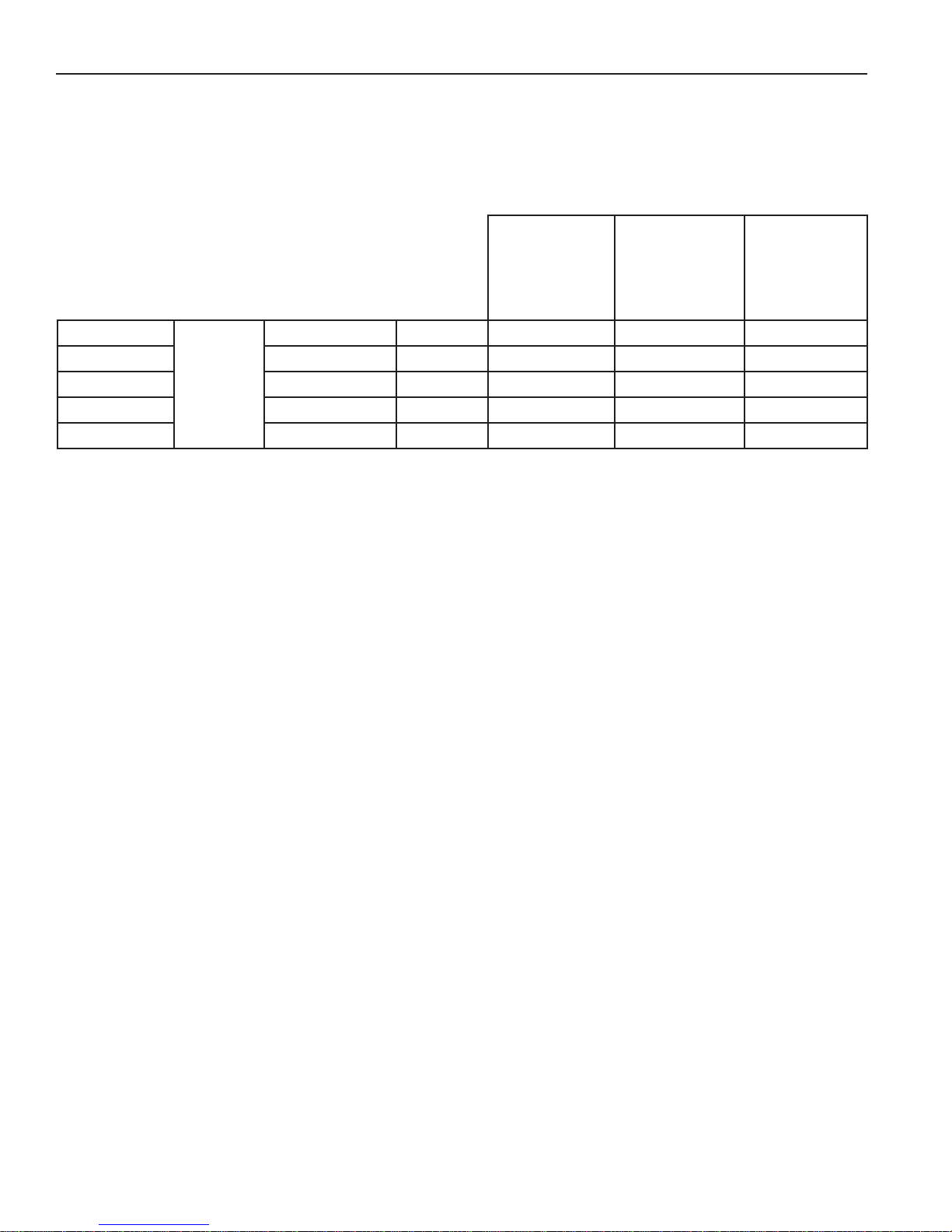
Adapter Kits
The chart below outlines the Hendrickson Suspension Tool packages and Adapter Kits available for specific
Hendrickson applications. If you currently own one tool package, consider purchasing adapter kits for other
specific applications.
Hendrickson Adapter Kits available
Hendrickson
Tool
Package
Part No.
4246
4247
4261
4274
4275
Tool
Packages
include
items
marked
w/ 4
No. 2510A
Air/Hyd. Pump
(w/ hose &
coupler)
4 4 4
4 4 4
4 4 4
No. 4250
(Volvo, Navistar,
No. 4263
and Paccar)
Bare Tool
4 4
4 4
No. 4254
(Comfort Air,
Primaxx EX, and
FCCC V-Ride)
No. 4255
(AIRTEK NXT
[rear bushing
only])
18
Page 21
Inspection and Maintenance
CAUTION: To prevent personal injury,
Only qualified personnel shall perform inspections to this Hendrickson Rear Suspension
•
Bushing Tool.
Before each use, an approved inspector must inspect the suspension bushing tool for bends,
•
cracks, dents, elongated holes, or missing hardware. If damage is found, discontinue use.
Use only those repair parts called out in the parts list in this document. Items found in the parts
•
list have been carefully tested and selected by OTC.
Maintenance
To prevent contamination from entering the hydraulic system and damaging the cylinder, keep the cylinder
clean. When the cylinder is not in use, keep the piston rod fully retracted and stored upside down. Use
protective covers on disconnected quick couplers.
Disposal
At the end of its useful life, dispose of the suspension bushing tool according to federal, state, and local
regulations.
Order replacement parts
at OTCparts.com
This document contains product parts lists and information regarding
operation and maintenance. Items listed in the parts list have been carefully
tested and selected by OTC. Therefore, use only OTC replacement parts.
Product questions may be directed to the OTC Technical Service Department
at (800) 533-6127.
19
Page 22

655 Eisenhower Drive
Owatonna, MN 55060 USA
Phone: (507) 455-7000
Tech. Serv.: (800) 533-6127
Fax: (800) 955-8329
Order Entry: (800) 533-6127
Fax: (800) 283-8665
International Sales: (507) 455-7223
Fax: (507) 455-7063
© Bosch Automotive Service Solutions Inc. Form No. 575168 Rev. C, June 12, 2018
 Loading...