


High Lift Transmission Jack
525197
Head Assembly
Form No. 102737
Parts List &
Operating Instructions
for: 1728
014-00942
Max. Capacity: 1,000 lbs. at 90 PSI
The High Lift Transmission Jack is designed
for the installation and removal of automobile
transmissions.
Safety Precautions
CAUTION: To prevent personal injury and damage to equipment,
Read, understand, and follow all instructions, including the ANSI B30.1 safety code for
•
jacks.
Wear eye protection that meets the requirements of ANSI Z87.1 and OSHA.
•
Inspect the jack before each use; do not use the jack if it’s damaged, altered, or in poor
•
condition.
A load must never exceed the rated lifting capacity of the jack.
•
Use the jack on a hard, level surface.
•
Never move the jack with a load any higher off the ground than necessary. SLOWLY AND
•
CAREFULLY move the jack around corners, because the load could tip.
Do not modify the jack or use adapters unless approved or supplied by OTC.
•
Lower the jack slowly and carefully while watching the position of the load.
•
Use only approved hydraulic fluid (Chevron AW Hydraulic Oil MV or equivalent). The use of alcohol,
•
hydraulic brake fluid, or transmission oil could damage seals and result in jack failure.
This guide cannot cover every situation, so always do the job with safety first.

Parts List & Operating Instructions
Form No. 102737, Sheet 1 of 5, Back
Operating Instructions
This is a two-stage transmission jack. The air stage is designed to quickly move the adapter into position, and
is completed with an automatic lock function that prevents loss of load. The following hydraulic stage is designed
to align the adapter with the transmission.
1. Lift the vehicle on a hoist.
2. Position the jack under the transmission.
3. Connect the air supply to the jack. (90 psi of clean, dry air is required for the capacity of this jack.)
4. Press the pedal marked UP to raise the adapter until the cylinder locks into place (at about 20 inches). The
air hose can be removed at this time.
CAUTION: If a load is transferred to the adapter when the air cylinder is only partially raised, the
cylinder will drop suddenly. To eliminate this problem, always raise the cylinder to the point where the
mechanical lock engages.
5. Check the placement of the jack. The transmission’s center of weight, or balance point, should be centered
over the jack adapter, with the power output end located over the adapter bracket between the chains. The
jack’s mechanical lock must be engaged.
6. Close the hydraulic release valve by turning the knob clockwise (CW).
7. Pump the jack handle to finish raising the adapter to the transmission. Use the controls on the adapter to
roll or tip the adapter as needed to align it with the transmission.
8. Push in the four adapter brackets until they touch the transmission. Use the chains to secure the
transmission to the adapter.
9. Support the engine, and remove the transmission according to instructions in the vehicle service manual.
10. Slowly turn the hydraulic release valve counterclockwise to lower the hydraulic stage. Lower the air stage
by pressing the DOWN foot pedal. If the load is already resting on the mechanical lock, attach the air hose,
and press the UP pedal briefly so the mechanical lock will release. The air stage should then lower when
the DOWN pedal is pressed.
Bleeding Air from the Hydraulic System
Air can accumulate within a hydraulic system during shipment or after prolonged use. This entrapped air causes
the jack to respond slowly or feel “spongy.” To remove the air:
1. Tilt the jack onto two casters with the pump handle positioned below the cylinder.
2. Open the release valve by turning the knob counterclockwise (CCW).
3. Pump the handle until resistance is felt.
4. Close the release valve by turning the knob all the way clockwise (CW).
5. Continue pumping the handle while returning the jack to its upright position.
Parts List & Operating Instructions Form No. 102737
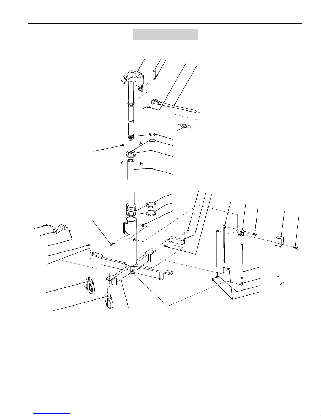
Jack Assembly
57
31
1
2
3
7
10
11
12
13
14
5
6
8
9
16
15
17
18
19
5
21
22
16
30
17
28
55
56
27
23
24
25
17
26

Parts List & Operating Instructions
525197 Head Assembly
Form No. 102737, Sheet 2 of 5, Back
45
46
47
32
29
39
4
44
43
42
41
40
39
38
33
37
36
33
48
34
37
49
50
29
51
54
35
32
34
33
32
47
52
53
33
Shaded areas reflect the last
revisions made to this form.
Parts List & Operating Instructions Form No. 102737
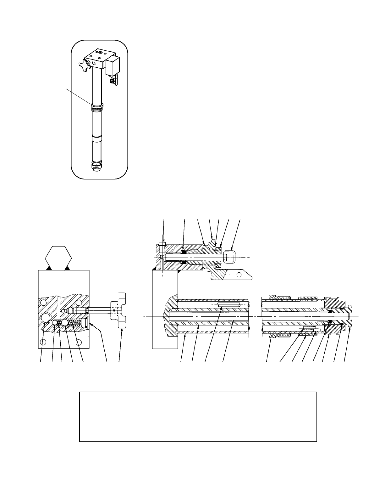
Hydraulic Unit
If the hydraulic unit needs service, it can be removed easily for repair or
shipment to a manufacturer-approved service center. If the unit is
Gland Nut
shipped, remove the platform assembly and handle to minimize package
size and weight. The hydraulic unit will separate from the jack by
removing the gland nut.
Hydraulic Unit Detail
65,66 63 62 61 60 59 64
85 84 83 82 81 85 80 79 78 77 76 74,75 73 72 71 70 69 68 67
Refer to any operating instructions included with the product for detailed information about
operation, testing, disassembly, reassembly, and preventive maintenance.
Items found in this parts list have been carefully tested and selected by OTC. Therefore: Use
only OTC replacement parts!
Additional questions can be directed to the OTC Technical Services Department.

Parts List & Operating Instructions
Item
No.
Part
No.
No.
Req'd
Description
1 1728-01 1 Hydraulic Unit
2 1728-02 2 Retaining Ring (1/8")
3 1728-03 1 Pump Shaft
4 1728-04 1 Transmission Bracket
5
1728-05 4 Roll Pin (1/4" x 1-1/2")
4
6 1728-06 1 Pump Handle Rod
7 1728-07 1 Handle Grip (7/8" ID)
8
9
10 1728-10 1 Gland Nut (4" bore;
11 1728-11 1 Piston Rod
12
13
1728-08 1 Wiper Ring (2")
u
1728-09 1 Felt Ring (2-3/4" OD)
u
507530 1 Gland Nut (4" bore;
(for serial no. 83-225639 and below)
507531 1 Piston Rod
1728-12 1 Seal (4" dia.)
u
1728-13 1 Ring Wiper (4" bore)
u
(for serial no. 83-225640 and above)
for serial no. 83-225639 and below)
for serial no. 83-225640 and above)
14 1728-14 1 Self-locking Nut (1/4"-20)
15 1728-15 1 Pedal (UP)
517189 1 Pedal (UP)
(for serial no. 48-020001 and above)
16 1728-16 2 Rivet (1/4" x 1-3/4")
17 1728-17 4 Palnut (1/4")
517190 4 Palnut (1/4")
(for serial no. 48-020001 and above)
18 1728-18 2 Control Rod
517186 2 Control Rod
(for serial no. 48-020001 and above)
19 1728-19 1 Air Valve
21 1728-21 1 Valve Cover
22 1728-22 1 Cap Screw (1/4" x 1-3/4")
23 1728-23 1 Pipe (1/4" x 14-3/4")
24 1728-24 2 Street Elbow (1/4")
25 1728-25 2 Rod End
517187 2 Rod End
(for serial no. 48-020001 and above)
26 1728-26 1 Base Weldment
27 1728-27 2 Caster (4")
28 1728-28 2 Caster w/ Brake (4")
29 1728-29 2 Self-locking Nut (1/2"-13)
30 1728-30 1 Pedal (DOWN)
517188 1 Pedal (DOWN)
(for serial no. 48-020001 and above)
31 1728-31 1 Spring
32 1728-32 3 Drilled Spacer
33 1728-33 5 Roll Pin (3/16" x 7/8")
34 1728-34 2 Cap Screw
35 1728-35 1 Side Tilt Crank
36 1728-36 1 Spacer (not drilled)
37 1728-37 2 Tilt Nut
38 1728-38 4 Ratchet Assembly
39 1728-39 2 Transmission Bracket (long)
40 1728-40 1 Chain & Snap Assembly
517191 1 Strap Assembly
(for serial no. 48-020001 and above)
41 1728-41 1 Transmission Bracket (short)
42 1728-42 1 Chain (1/0; 42 links)
517192 1 Cap Screw & Washer
(for serial no. 48-020001 and above)
43 1728-43 4 Roll Pin (1/4" x 7/8")
44 1728-44 1 Adapter Weldment
45 1728-45 3 Angle Stop

Parts List & Operating Instructions Form No. 102737
Item
No.
Part
No.
No.
Req'd
Description
46 1728-46 1 Side Tilt Shaft
47 1728-47 2 Tilt Trunnion
48 1728-48 1 Pivot Bracket
49 1728-49 4 Cap Screw (3/8" x 1)
50 1728-50 4 Lockwasher (3/8")
51 1728-51 1 Hydraulic Unit Bracket
52 1728-52 1 Long Tilt Shaft
53 1728-53 1 Crank (lower)
54 1728-54 1 Tow Handle
55 1728-55 4 Hex Jam Nut (1/2")
56 1728-56 4 Lockwasher (1/2")
57 1728-57 4 Self-locking Cap Screw (3/4" long)
59
60
1728-59 1 Jam Nut (3/4"-l 6 UNF)
4
1728-60 1 Rim Washer
4
61 1728-61 1 Swivel Pivot
62
63
64
1728-62 1 Pump Sleeve
4
1728-63 1 Seal (13/16" OD x 7/16" ID x 1/4" deep)
4ju
1728-64 1 Plunger Weldment
4j
65 1728-65 1 Soc. Hd. Cap Screw (5/16"-18 UNC)
66 1728-66 1 Metallic Gasket
67 1728-67 1 Ram Guide
68
1728-68 1 O-ring (1" OD x 3/16" ID x 3/32" dia.)
u
69 1728-69 1Cap
70
1728-70 1 Seal (11/16" OD x 7/16" ID x 3/16" deep)
u
71 1728-71 1 Magnet
72 1728-72 1 Spacer
(for serial no. 83-225639 and below; not needed for
serial no. 83-225640 and above)
73 1728-73 1 Suction Tube (22-5/8" long)
74
75 1728-75 1 Packing Gland (2" bore;
1728-74 1 Felt Packing Gasket
u
507532 1 Packing Gland (2" bore;
for serial no. 83-225639 and below)
for serial no. 83-225640 and above)
76 1728-76 1 Ram
77 1728-77 1 Suction Tube (6" long)
78 1728-78 1 Cylinder Tube
79 1728-79 1 Reservoir Tube
80 1728-80 1 Release Knob Sub-assembly
81 1728-81 1 Compression Spring (.406 OD)
82 1728-82 1 Ball (3/8" dia. RC)
83 1728-83 1 Compression Spring (.250 OD)
84 1728-84 1 Ball (1/4" dia. RC)
85 1728-85 2 Plug w/ o-ring
221089 1 Two-piece Plunger Kit (items marked with
221088 1 Complete Plunger Kit (items marked with
221090 1 Soft Seal Kit (3") (items marked with u)
525797 1 Head Assembly
Available Kits
4
j)
)

Parts List & Operating Instructions
221598 Adapter Set
(used on 014-00942)
Form No. 102737, Sheet 4 of 5, Back
1
6
5
4
Item
No.
1 54370 1 Adapter
2 313559 1 Mounting Bracket
3 16469 4 Cap Screw
4 10204 2 Hex Nut
5 221597 1 Stem
6 10208 1 Hex Nut
Part
No.
No.
Req'd
3
Description
2

Parts List & Operating Instructions Form No. 102737
Maintenance
Adding Oil to the Hydraulic Stage
1. Position the jack upright with all four casters on the floor. Lower the hydraulic
(See Figure 1)
Mounting Bolts
stage.
2. Remove the transmission adapter by removing the four bolts holding it to the
jack.
3. Clean the top of the jack, concentrating on the area around the filler plug.
Filler
Plug
4. Remove the release knob. This serves as a vent while the reservoir is being
filled.
5. Remove the filler plug.
6. Slowly add Mobile DTE #11 oil (or equivalent) until the reservoir overflows.
7. Install the release knob.
8. Install the filler plug, and mount the adapter.
Cleaning the Air Control Valve
(Item numbers refer to Figure 2)
Figure 1
Release
Knob
1. Remove the fittings (1) from the ends of the air control valve. Clean the screen.
2. Insert a nail or stiff wire into the center of the control body (3), and push each valve spool (2) out of the body.
3. Look for foreign matter embedded in the valve seals (4). If this is the case, remove the screw (5) and cup
(6) from the end of the spool, clean the seat, turn it over, and reassemble.
4. Lubricate the valve spool with light chassis grease.
5. Assemble the valve in this order: insert the valve spools; insert the springs; assemble the hexagon fittings
into the body.
1
5
6
4
Air Valve (1728-19)
1 Fitting
2 Spool
3 Body
2
4 Seal
5 Screw
3
Figure 2
6 Cup
2
4
6
5
1

Parts List & Operating Instructions
Preventive Maintenance
IMPORTANT: The greatest single cause of failure in hydraulic units is dirt. Keep the transmission jack
clean and well lubricated to prevent foreign matter from entering the system. If the jack has been exposed to
rain, snow, sand, or grit, it must be cleaned before it is used.
1. Store the jack in a well-protected area where it will not be exposed to corrosive vapors, abrasive dust, or
any other harmful elements.
2. Lubricate moving parts at least once per month.
3. Regularly wipe the cylinder columns with a clean cloth to remove dirt and abrasives.
4. Replace the oil in the reservoir at least once per year.
5. Inspect the jack before each use. Take corrective action if any of the following problems are found:
a. Cracked or damaged housing d. Scored or damaged piston rod
b. Excessive wear, bending, or other damage e. Loose hardware
c. Leaking hydraulic fluid f. Modified or altered equipment
Troubleshooting Guide
Repair procedures must be performed in a dirt-free environment by qualified personnel who are familiar with
this equipment.
Trouble Cause Solution
Air Stage - Air leak causes 1. Air valve is dirty
mechanical lock to engage or
erratic cylinder action
Air Stage - Cylinder does not 1. Mechanical lock is engaged
lower when DOWN pedal is
pressed
Hydraulic Stage - Cylinder does 1. Jack is out of prime
not raise
Hydraulic Stage - Cylinder lifts 1. Release valve is not sealing
load, but doesn’t hold
2. System oil is dirty
Hydraulic Stage - Cylinder does 1. Low oil level
not raise to full height
1. Follow instructions to
clean air valve.
1. Attach air hose and
press UP pedal until
cylinder is at full line
pressure. Press DOWN
pedal and mechanical
lock should release.
1. Follow instructions
on bleeding air from the
hydraulic system.
1. Clean or reseat
release valve ball.
2. Replace hydraulic oil.
1. Check oil level.
Follow instructions
on adding oil.
OTC puts everything within reach.
Learn more about garage accessories we have.
 Loading...