

Otai Pluto Fisheye, Pluto, Pluto Power, Pluto Max dbdc, Pluto Vision User Manual
...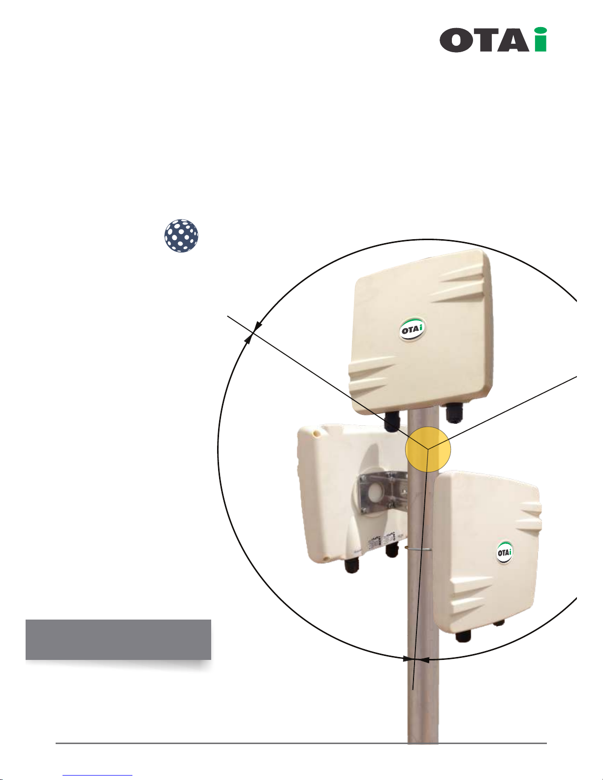
120°
120°
120°
www.onnettechnologies.com
always innovative
Point to Multi-Point
Enterprise Wireless Solution
plut
fisheye
User Manaul

About Us
Onnet Technologies And Innovations LLC
The rst and only manufacturing set up of wireless and green power equipments in Middle East and Africa Region.
OTAi is committed to deliver always-on-reliable enterprise scale wireless infrastructure for Voice, Data and Video
trafc and impervious to interference and harsh environmental conditions from -20° to +80°.
OTAi's enterprise scale wireless solutions are robust, feature rich and cost effective. It can be easily scaled /
upgraded to all future requirements of any organization.
The resilient products provide Point to Point, Point to Multi-Point and Any Point to Any Point Enterprise WAN
connectivity used for enhancement of Public Safety Networks, secure long distance Enterprise connectivity
between multiple locations. Organizations such as Governments, SME, Oil Fields, Defense, Telecom & Wireless
Internet Service Providers, Schools, College Campus, Hotels, Hospitals, Airports, Coffee Shops, Warehouse etc
can be connected over wireless to there center database for increase efciency.
OTAi’s is leading last mile solutions provider using OFDM based 802.11a/g, 802.11-N and 802.16 Wi-max
technologies to suit the most harsh environment and capable of delivering long distance Point to Point, Point
to Multi-Point networks.
Enterprise Wireless Connectivity
Communication over IP (data networking) for high speed Voice, Data & Video has
become major part of today’s business. Seamless wireless connectivity across the
enterprise has always been a feather to any organization which allows real time
connectivity and usage from centralized database.
It has attracted more focus and are very much in demand even during
recession time to protect each cent of an organization and retain the
prot growth rate.
Our solution are
Extreme smart, comprehensive and cost effective.
Fully customized design for best efciency even in harsh
environmental conditions.
Enterprise outdoor long distance Point to Point and Point to
Multi-Point connectivity.
Enterprise Wi-Fi solution for Villas, Hotels, Institutes, Hospitals,
ISP’s, SMB etc..
Solar power solutions to back remote installations.
always innovative

ProductDetail......................................4-15
UserManual.......................................16-54
QuickReferenceChart.......................55-76
FlowChartforTechnical/
TrainedEngineer.............................77-89
Table of Contents
always innovative

Product Details...................................................05-06
Interfaces............................................................07-09
Checklist ..................................................................10
MountingThePluto................................................11
WaterproofIO(Rj45)Connection.......................12-13
ArrangingEthernetCables......................................14
InterComponentConnection..................................15
Table of Contain
www.onnettechnologies.com
always innovative
Pluto Product Details
Point to Multi-Point
Enterprise Wireless Solution

always innovative
Pluto power is a high-performance
wi re le ss me sh ro ut in g d e v i c e
designed SPECIALLY for the most
challenging and Harsh Environments
w h e r e w i r e d c o n n e c t i v i t y i s
impractical or unavailable.
Key Features
256bit Ultra Secure Encryption
Full QoS With Traffic Shapping
Point to Point, Point to Multipoint &
Any Point to Any Point
GUI, Telnet, SSH
Watchdog Timer
Built-in HotSpot Clients
(Sputnik / Chilli Spots / HotSpot System)
Plus PPPoE Server / Client
MESH Ready
OSLR & Static Routing
Long Range upto 40Kms*
OFDM MIMO Technology
Premium Quality and Very High
Gain Antenna
High TX Power
*(Depending on Antenna and Quality of installation)
Pluto series enhances enterprise level performance, management and quality of services with very high performance.
The perfect combination of enterprise grade mesh OS along
with premium quality high gain antenna and robust IP67
enclosure makes pluto the first choice for people who
deserve unparalleled speed, Link Reliability, low latency and
seamless hand-off for voice, HD-quality video and other
real-time applications across long-distance outdoor wireless
Point to Point and Multipoint to MultiPoint Networks.
Pluto power is ideal for deployment in metropolitan and
industrial areas like oil fields, mines, shipping ports, WISP,
Educational campus etc..
Pluto power offers wide choice of integrated antenna for
flexible outdoor wireless deployments using the 2.199 –
2.499 GHz or 4.9GHz- 6.1Ghz frequency band including
2.4GHz and 5.8GHz ISM band.
The device can be configured as AP /Client / Client Bridge /
Mesh Repeater for Wi-Fi Applications or as a Point-to-Point,
Point-to-Multipoint and full mesh backhaul.
Intelligent wireless mesh routing
Integrated OTA mesh OS, adaptive wireless routingi
technology supported by Spanning Tree Protocol
automatically optimizes traffic routes between wireless mesh
routers and creates a truly adaptive mesh infrastructure.
The mesh infrastructure adjusts dynamically to traffic levels
and RF signal strength to ensure high availability and
optimal performance.
Seamless mobility
Advanced algorithm of quick RF routing and bridging
capabilities of OTAi software allows Wi-Fi clients to move
between wireless mesh routers in very less time (with in
threshold time ) maintaining a seamless connection for
latency-sensitive applications, such as video and voice.
Product Details
always innovative
Product Details
Enclosure Size : 185x185x56mm / 7.4" x 7.4" x 2.2"
Frequency Options : 2.4-2.485, 2.3-2.7, 5.1-5.9, 4.9-6.1GHz.
Integrated Antenna Gain Options : 12dBi(DP), 14dBi(SP) for 2.4GHz
Weight : 0,6kg / 1,3lbs
16dBi (DP), 19dBi(SP) for 5GHz
16dBi (DP) for 4.9-6.1GHz
3.3-3.8, 5.4-6.1GHz
Enclosure Size : 270x270x75mm / 10.6 x 10.6 x 2.9"
Frequency Options : 2.4-2.485, 2.3-2.7, 5.1-5.9, 4.9-6.1GHz.
Integrated Antenna Gain Options : 14dBi(SP) 14dBi(DP) for 2.4GHz
Weight : 1,2kg / 2,65lbs
18dBi (DP), 21dBi(SP) for 5GHz
18dBi (DP) for 4.9-6.1GHz
18dBi (DP) for 5.9-6.4GHz
10dBi (DP) for 2.4+12dBi (DP) for 5GHz
16dBi (DP) for 3.3-3.8GHz
19dBi (SP) for 3.3-3.8GHz
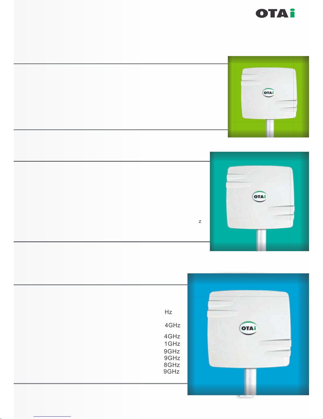
Enclosure Size : 385 x 385 x 80mm
Frequency Options : 2.4-2.485, 2.3-2.7, 5.1-5.9,
4.9-6.1GHz, 3.3-3.8, 5.4-6.1GHz
Integrated Antenna : 14dBi (DP), 120°wide angle 2.4GHz
Gain Opt
Weight : 2.4kg / 5.3lbs
16dBi (DP), 120°wide angle 2.4GHz
18dBi (DP) for 4.9-6.1GHz
23dBi (SP) for 5.1-5.9GHz
21dBi (DP) for 5.1-5.9GHz
21dBi (SP) for 3.3-3.8GHz
19dBi (TP) for 5.1-5.9GHz

always innovative
Interfaces
Integrated Premium Quality
High Gain Antenna
Rj45 PoE Inlet
(Waterpr oof)
Power + Data (a) Passive PoE as per Radio
(b) 3af Complaint Port
1
Pluto with Internal Integrated Antenna + PoE
Rj45 PoE Inlet
(Waterpr oof)
Power + Data (a) Passive PoE as per Radio
(b) 3af Complaint Port
2
Pluto with External Antenna + PoE
External
Antenna Port
N-Female
Integrated Premium Quality
High Gain Antenna
Rj45 PoE Inlet
(Waterpr oof)
Power + Data (a) Passive PoE as per Radio
(b) 3af Complaint Port
Redunda nt
Data Por t
DUAL
Data Por t
3
Pluto with Integrated Antenna and
Redundant Data Port

always innovative
Interfaces
Integrated Premium Quality
High Gain Antenna
Rj45 PoE Inlet
(Waterpr oof)
Power + Data (a) Passive PoE as per Radio
(b) 3af Comply Port
Redunda nt
PoE Port
DUAL
Data Por t
4
Pluto with Integrated Antenna and Redundant Passive PoE Port
for Cascading another PoE Device working on same PoE Voltage
Integrated Premium Quality
High Gain Antenna
Rj45 PoE Inlet
(Waterpr oof)
Power + Data (a) Passive PoE as per Radio
(b) 3af Comply Port
Redunda nt
Data Por t +
3af PoE O ut Po rt
DUAL
Data Por t
5
Pluto with Integrated Antenna and Redundant Data Port + 3af PoE Out Port
for Connectivity of IP Camera / IP Phones or any Other 3af PoE Device
PoE IN = PoE OUT
PoE IN = PoE OUT - 48Vdc,3af Complied with
(12/15/18/24)Vdc Detection
External Antenna Port
N-Female x2
Rj45 PoE Inlet
(Waterpr oof)
Power + Data (a) Passive PoE as per Radio
(b) 3af Complaint Port
Redunda nt
Data Por t +
3af PoE O ut Po rt
DUAL
Data Por t
6
Pluto with External Antenna and Redundant Data Port + 3af PoE Out Port
for Connectivity of IP Camera / IP Phones or any Other 3af PoE Device
PoE IN = PoE OUT - 48Vdc,3af Complied with
(12/15/18/24)Vdc Detection

always innovative
Interfaces
Integrated Premium Quality
High Gain Antenna
Rj45 PoE Inlet
(Waterproof)
Power + Data (a) Passive PoE as per Radio
(b) 3af Complaint Port
Redundant
Data Port +
3af PoE Out Port
DUAL
Data Port
7
Pluto with Integrated Antenna & PoE Switch for Connectivity of
IP Camera / IP Phones or any Other 3af PoE Device
PoE IN = PoE OUT - 48Vdc,3af Complied with
48Vdc Detection
Rj45 PoE Inlet
(Waterproof)
Power + Data (a) Passive PoE as per Radio
(b) 3af Complaint Port
Passive PoE
Out Ports
DUAL
Data Port
8
Pluto with Integrated Antenna and Passive PoE Switch for Connectivity of
Multiple PoE Device
PoE IN = PoE OUT
(12-48)Vdc (12-48)Vdc
Integrated Premium Quality
High Gain Antenna

List of the components necessary for establishing a minimum Pre WiMAX network.
Some of the items are
optional.
Sr.No ITEM
Remark
1
2
3
4
5
6
7
Pluto 1
Pluto 2
Computer / Laptop
PoE Adaptor
Ethernet Cable
Pluto Mounting Kit
Clamp
OTAi provides 2.4 GHz & 5.8 GHz Pluto
Two laptops / Pc’s are required for installation and end to
end testing. Pc’s should have the standard conguration.
At least CAT -5e or higher to connect both the equipments to
PoE & PoE to PC.
Required to mount the equipment.
Any additional clamp (L mount or other) if required
(depending on the tower or equipment mounting location)
OTAi provides 2.4 GHz & 5.8 GHz Pluto
Power Over Ethernet. Single cable is used for power & data
in-out for RF equipment. The PoE adapter have two LAN ports,
onefor power+data out & second for data in.
Only experienced installation professionals who are familiar with local building and safety codes (wherever applicable) and
licensed by the appropriate government regulatory authorities should install outdoor units and antennas. Failure to do so
may void the OTAi Product warranty and may expose the end user or Service Provider to legal and nancial liabilities.
Select the optimal location for the equipment using the following guidelines:
The Pluto can be installed either on pole, tower or wall mounted clamp.
Its location should enable easy access to the unit for installation and testing.
The higher the placement of the equipment, the better the achievable link quality.
The equipment should be installed so that LoS should be clear from another unit.
The recommended distance between two antenna should be more than 5 meter.
always innovative
Checklist
Site Selection
always innovative
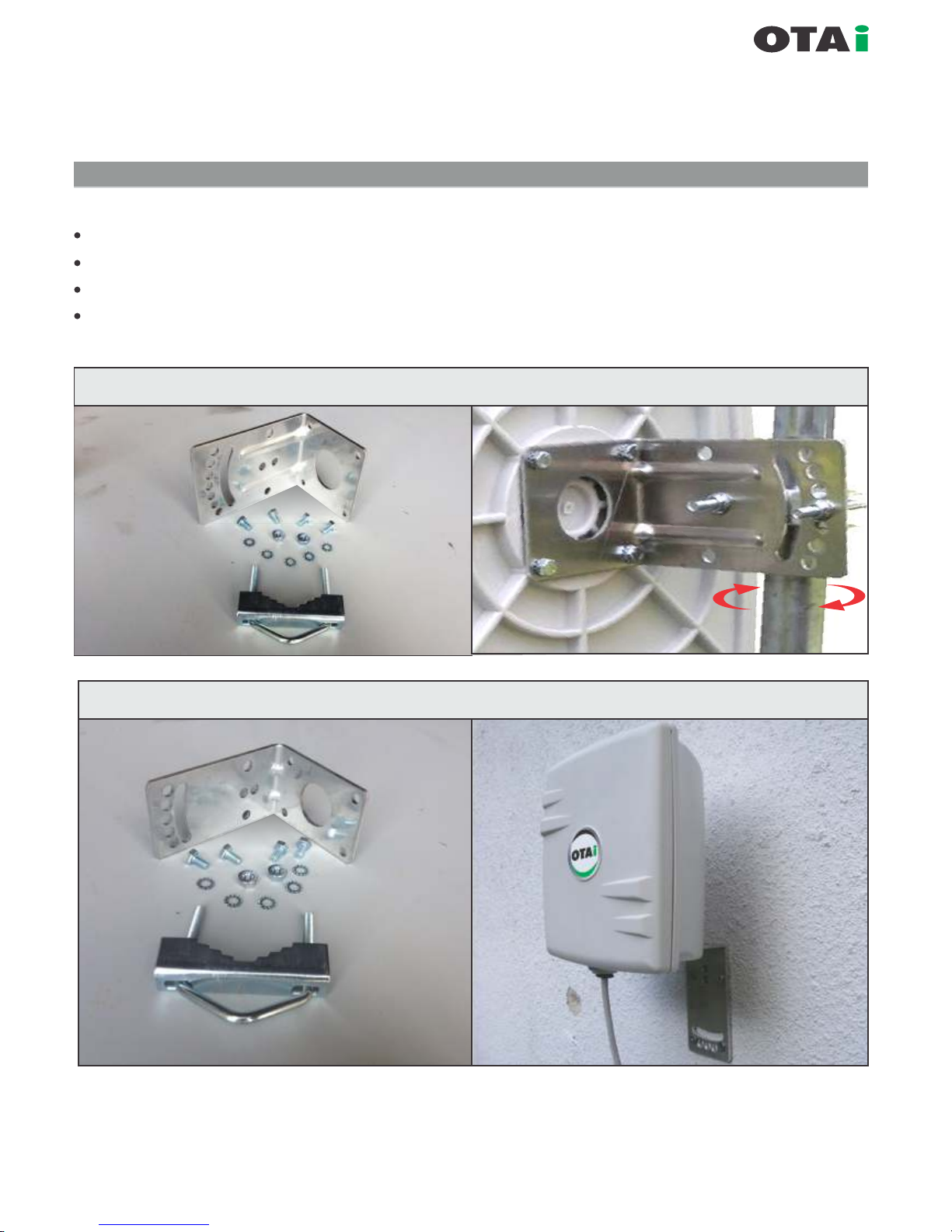
Mounting The Pluto
Mounting plate (L shape) and 1-U shape Bolt supplied with each unit.
One side of the mounting plate is directly connected with Pluto.
Another side of mounting plate has two pair of holes which are used to mount to a pole.
U bolt are mounted with Pluto to pole as illustrated in gure
Vertical Fixed Position Mounting
Wall Mounting for small body options
(The Pluto can be mounted as illustrated)
always innovative
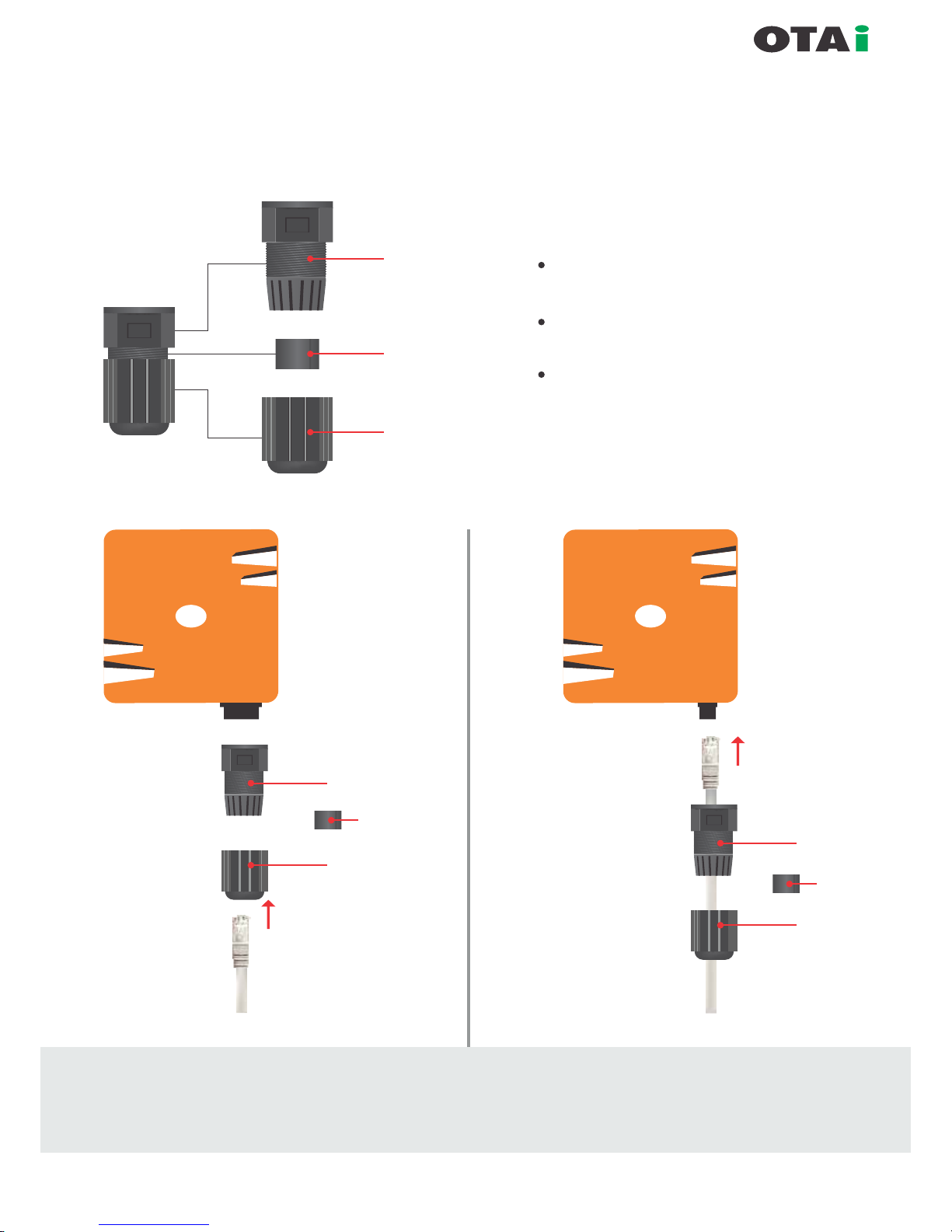
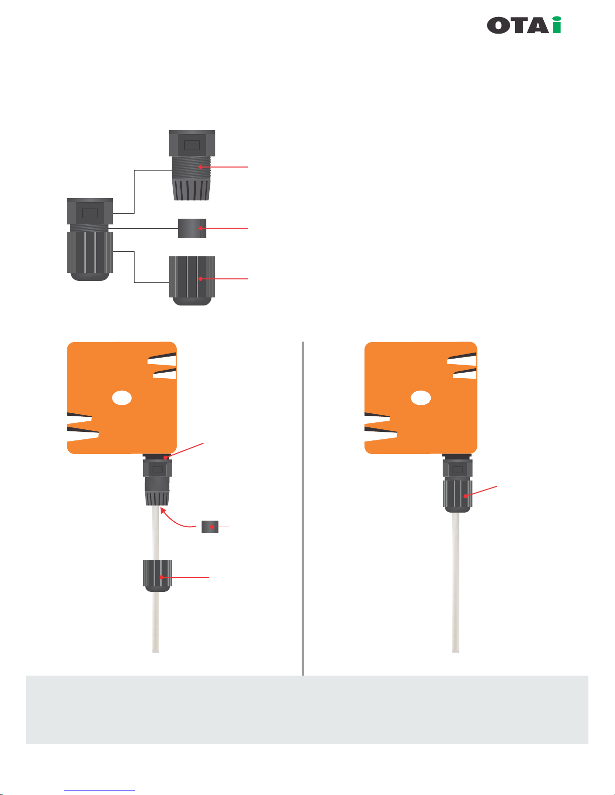
Waterproof IO (RJ-45) Connection
Part -1
Part -2
Part -3
}
Waterproof IO cap has
3 components as shown in gure.
Kindly separate them as part-1, part-2,
part-3.
Carefully follow the steps to avoid
damage to waterproof RJ-45 connector
xed with the device.
Part -1
Part -3
To Device
Part -1
Part -3
Part -2
Part -2
Step-2
Step-3
Strictly follow step-1 to step-5 to avoid damage to
waterproof RJ-45 connector of the radio
(PoE cable connectivity to Radio Device)
always innovative
Part -1
Part -2
Part -3
}
Waterproof IO cap has
3 components as shown in gure.
Kindly separate them as part-1, part-2,
part-3.
Carefully follow the steps to avoid
damage to waterproof RJ-45 connector
xed with the device.
Part -3
Part -2
Step-4
Rotate the part-1 to x
on RJ-45 connecter
on the body
Fix part-2 on
ethernet cable and
push it into part-1
Step-5
Rotate the part-3
to
x on part-1
Strictly follow step-1 to step-5 to avoid damage to
waterproof RJ-45 connector of the radio
Waterproof IO (RJ-45) Connection
(PoE cable connectivity to Radio Device)
always innovative
Arranging Ethernet Cables
The Pluto can be deployed outdoor and in harsh terrains. The Ethernet cables which originate from the
Equipment should be protected by IP67 Ethernet connector system.
Cat5 cable termination to Pluto Ethernet Port.
Ethernet Cables Requirements
Ethernet cable should be CAT 5 cable grade or better.
Ethernet cable should be crimped with RJ45 connectors on both sides.
IP 67 Ethernet Connector System (ECS) should be used at one end
which is exposed to outdoor conditions.
Ethernet cable length should be crimped as per the required length
from PoE to the Pluto. PoE is generally at the bottom of a tower or in
side the termination room.
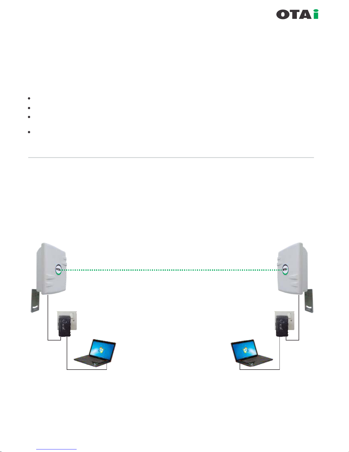
Figure gives a graphical representation of the basic connection involved in installing a minimum
network.
Arranging the computer / Laptop
Both Ends can be accessed from pc1 to pc2 respectively.
Outdoor AP / CPE
Outdoor AP / CPE
Power + Data
Data / LAN
PoE
Injector
Power + Data
Data / LAN
PoE
Injector
LAN POEPOE LAN

always innovative
Inter Component Connection
Pluto to PoE
Connect one end of ethernet cable to PoE (Power + Data) port of PoE injector supplied
along with device.
PoE to Computer
Connect LAN / Data port of PoE injector to your local LAN / Laptop or stand alone PC using CAT 5/6 cable properly
crimped.
Pluto Default IP / Subnet : 192.168.1.1 / 225.225.225.0
To access Pluto from any computer please ensure the computer has same IP range and Subnet
IP allocated to Pluto must be independent of the DHCP range of the network.
The static IP to device is preferred to be before DHCP range starting.
Connecting on LAN
The Pluto can be connected
to any LAN via a PoE. Any
computer connected to the
LAN can access the Pluto.
Care should be taken to
ascertain that the Pluto in
any LAN should have unique
IP address (same IP range).
Further, both the Pluto (in bench test) should not be connected to the same LAN (switch).
This might create an innite loop in the data path since any packet sent by Pluto 1 equipment will be received back
when the Pluto 2 resend on the network.
Power + Data
PoE
Injector
Data / LAN
Outdoor AP / CPE
Power + Data
PoE
Injector
Data / LAN
Outdoor AP / CPE
LAN PoE
LAN PoE
Example of IP Allocation
Native IP : 192.168.10.0
Subnet : 255.225.255.0
DHCP range : 192.168.10.50 to 192.168.10.200
IP for Pluto 1 : 192.168.10.5 / 255.255.255.0
IP to Pluto 2 : 192.168.10.6 / 255.255.255.0
IP for PC 1 connected to Pluto 1 : 192.168.10.10 / 255.255.255.0
IP for PC 2 connected to Pluto 2 : 192.168.10.11 / 255.255.255.0
NOTE : It is strictly recommended that unique
IP given to wireless devices must be before
DHCP range.
In this case it should be between
192.168.10.1 to 50.

Table of Contain
SETUP
Basic Setup...............................................................................................................17-20
DDNS.............................................................................................................................21
MAC Address Clone.......................................................................................................21
Advanced Routing.....................................................................................................22-23
Networking...............................................................................................................24-25
WIRELESS
Basic Setting.......................................................................................................26-29
Wireless Security.....................................................................................................30
MAC Filter................................................................................................................31
WDS.........................................................................................................................32
SERVICES
Services....................................................................................................................33
PPPoE Server ..........................................................................................................34
VPN..................................................................................................................... 34-35
SECURITY
Firewall.....................................................................................................................35
VPN Passthrough.....................................................................................................36
ACCESS RESTRICTIONS
WAN Access.......................................................................................................36-37
NAT / QoS
Port Forwarding........................................................................................................38
Port Range Forwarding.............................................................................................38
Port Triggering..........................................................................................................39
UPnP .......................................................................................................................39
DMZ ........................................................................................................................40
QoS..................................................................................................................... 40-42
ADMINISTRATION
Management........................................................................................................ 42-44
Keep Alive............................................................................................................44-45
Commands................................................................................................................46
WOL.......................................................................................................................... 46
Factory Defaults........................................................................................................47
Firmware Upgrade .......................................................................................... ..........48
Backup...................................................................................................................... 48
STATUS
Router.......................................................................................................................49
WAN.........................................................................................................................50
LAN.......................................................................................................................... 50
Wireless.................................................................................................................... 51
Bandwidth................................................................................................................ 52
Sys-Info.................................................................................................................... 53
Technical Support.....................................................................................................54
always innovative
Pluto User Manual
always innovative
Setup
Basic Setup
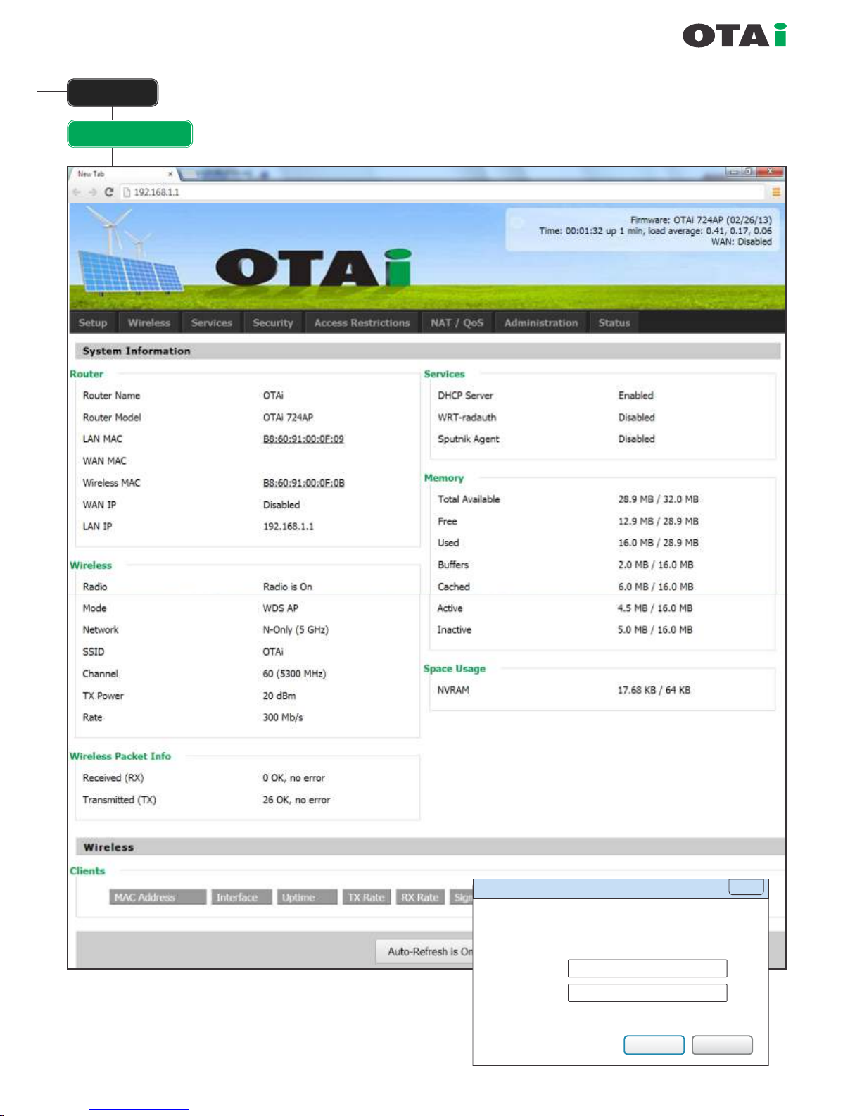
Default IP / Subnet : 192.168.1.1 / 225.225.225.0
Default User Name
: root
Default Password
: admin
Default DHCP Range
: 192.168.1.100 to 192.168.1.150
Default SSID : OTAi
Authentication Required
The server http://192.168.1.1:80 requires a username and
password. The server says: OTAi.
User Name:
Password:
root
admin
Log In
Cancel
X
always innovative
Setup
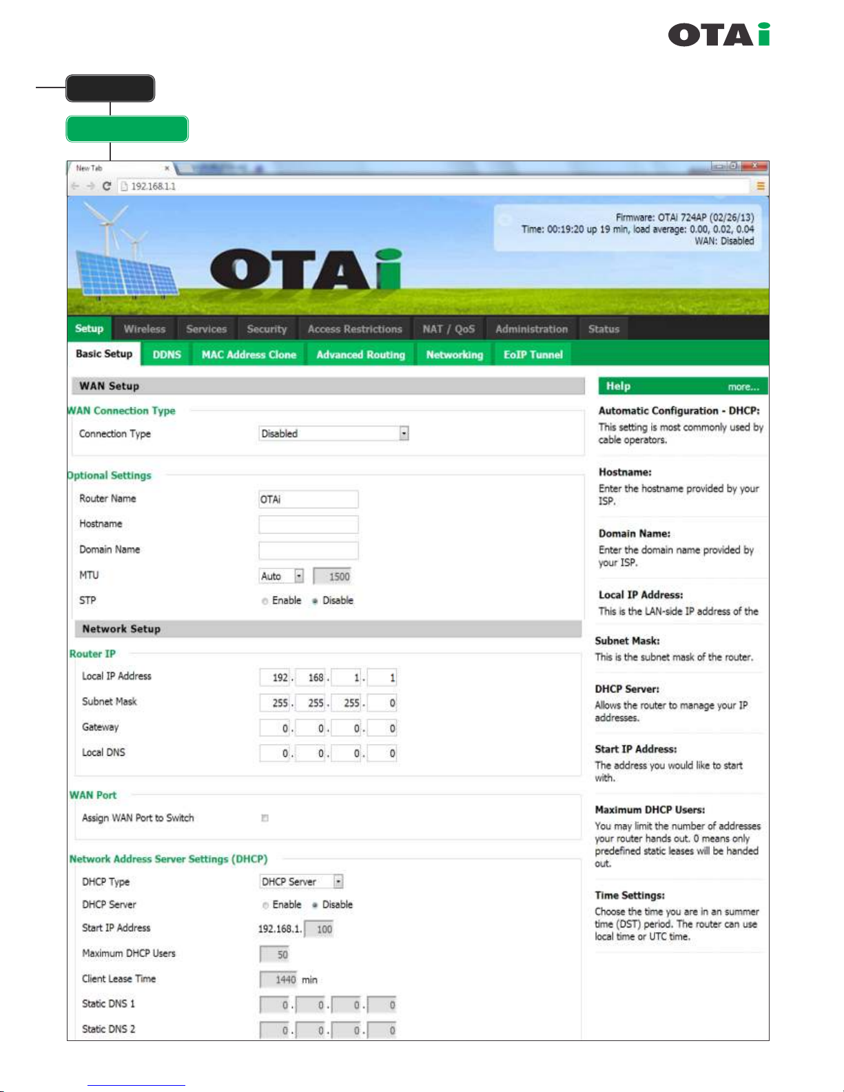
Basic Setup
Basic Setup
always innovative
Note : If the WAN PORT is disabled then the port can be used as extra LAN port.
OPTIONAL SETTING
Router Name : Name of the Router (OTAi by default)
Host Name : Name of the Host (empty by default)
Domain Name : Name of the Domain if any
(empty by default)
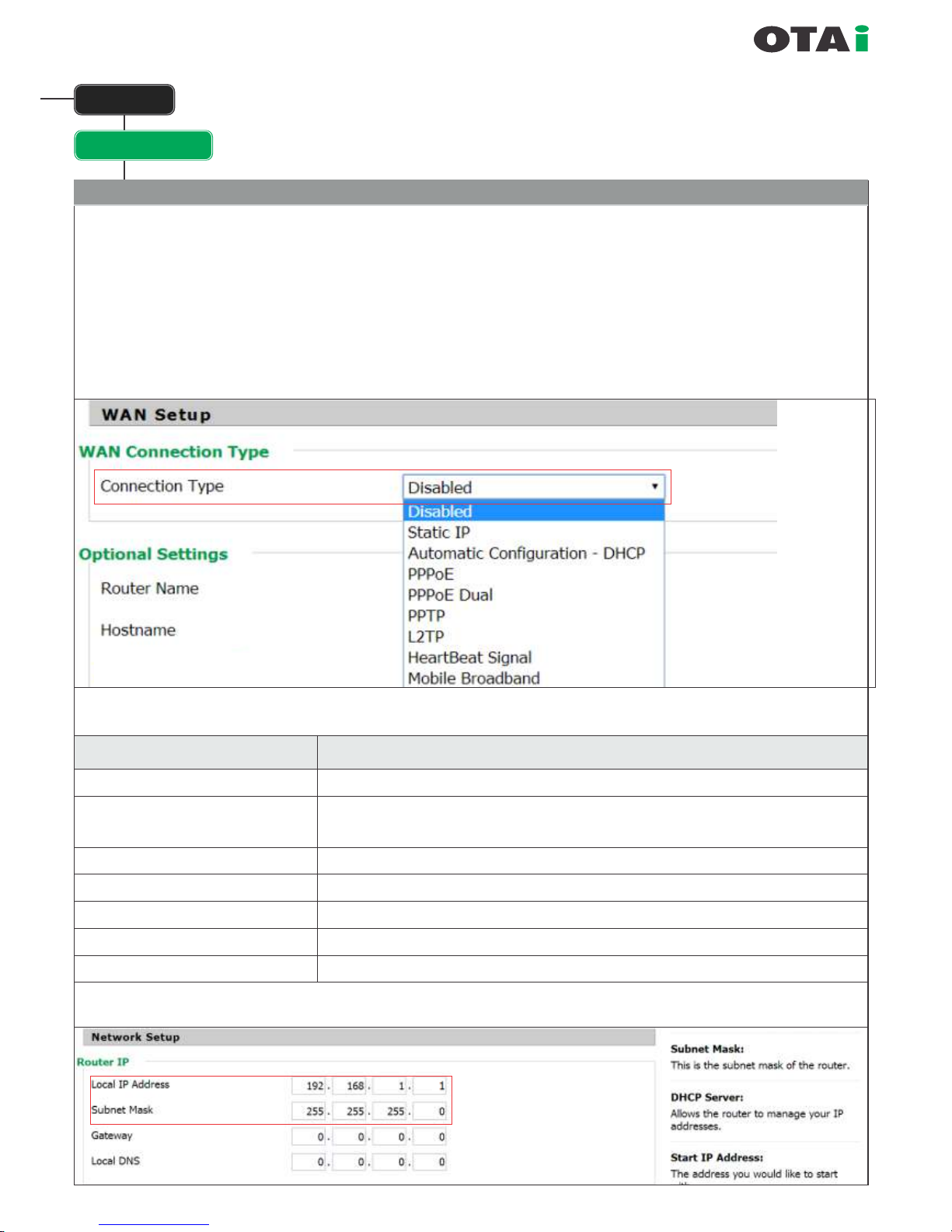
WAN Setup
WAN Connection Type :
Setup
WAN Connection Type
Description
Disabled
Static IP
Automatic Conguration - DHCP
PPPoE
PPTP
L2TP
Heartbeat Signal
WAN-Interface is disabled
A static IP-address will be used – you have to enter IP-address, Subnet mask,
Gateway und Server manually
The router obtains the IP-address from a DHCP-Server
Conguration as PPPoE-client, in case of VDSL enable the Checkbox „VDSL-Tagging"
Establish connection via PPTP
Establish connection via L2TP
Used in conjunction with a Heartbeat-signal, only used by certain ISPs (uncommon in the EU)
The Port behaves as standard LAN Port.
Change the default
IP address as desire.
(It is important that the IP Address
dened should be before DHCP Range)
Basic Setup
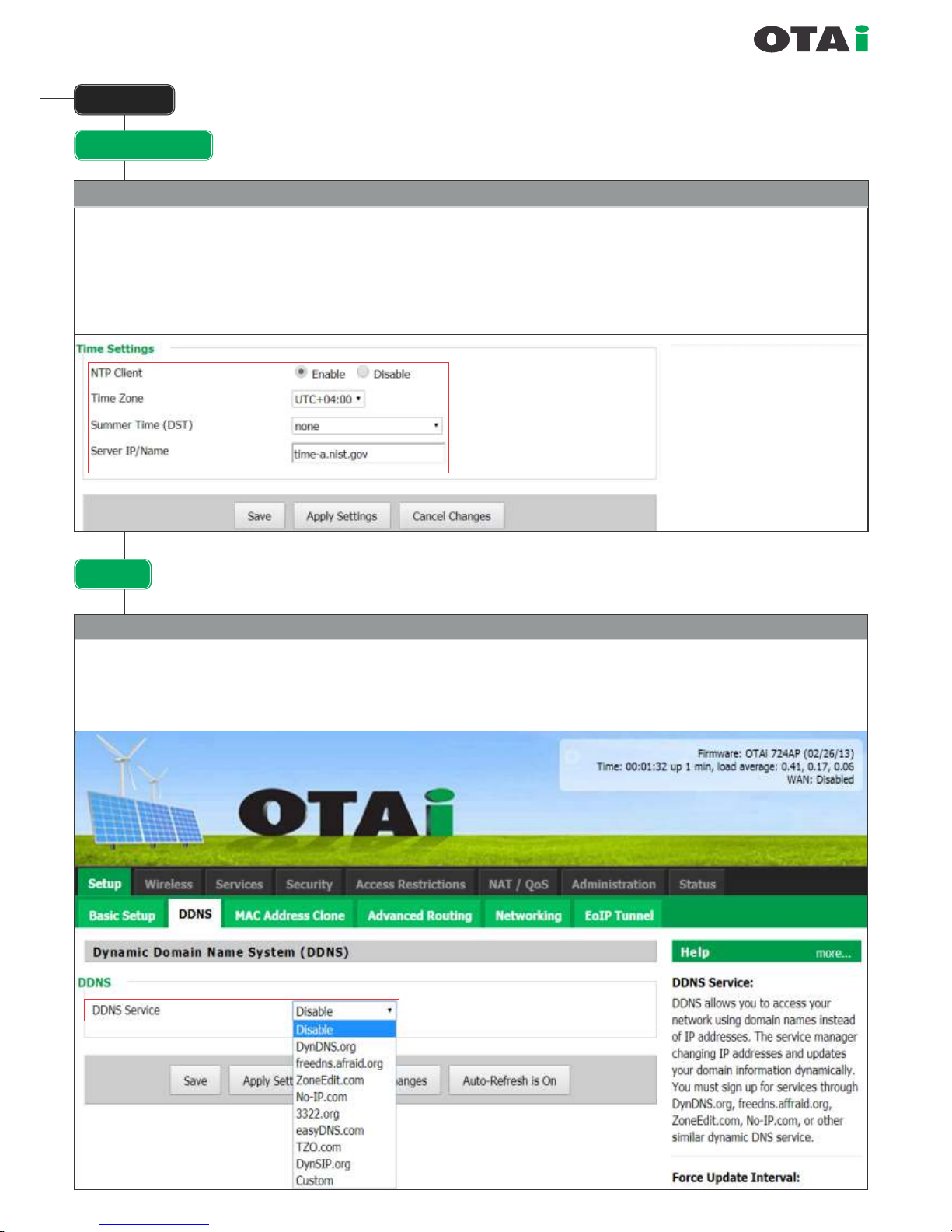
always innovative
Time Setting
NTP Client : Enabled by default. If the unit can go on the internet then it will automatically set its correct time.
Time Zone : What time zone it lies in Summer Time DST: If DST should be enabled.
Server IP/Name : If additional NTP server name needs to be inputted. By default there is a NTP server name in the unit.
Setup
for UAE
DDNS
Dynamic DNS allows the assignment of a DNS record to a dynamically assigned IP-address in the internet.
To achieve this it is required to run a Dyn DNS client that does announce a change of the external IP-address to the
Dynamic DNS services that does update the DNS record in time.
Dynamic Domain Name System (DDNS)

DynDNS Service
Description
Disabled
Default, no DynDNS
DynDNS.org
freedns.afraid.org
ZoneEdit.com
No-IP.com 3322.org
easyDNS.com
TZO.com
DynSIP.org
Custom
Individual DynDNS service conguration
always innovative
Setup
DDNS
MAC Address Clone
MAC-Address cloning is used to virtually assign another MAC-address for the LAN- or a WLAN-Interface then the one
encoded in the hardware.
MAC Address Clone
To use this option you have to create an account to given list of DynDNS services.
always innovative
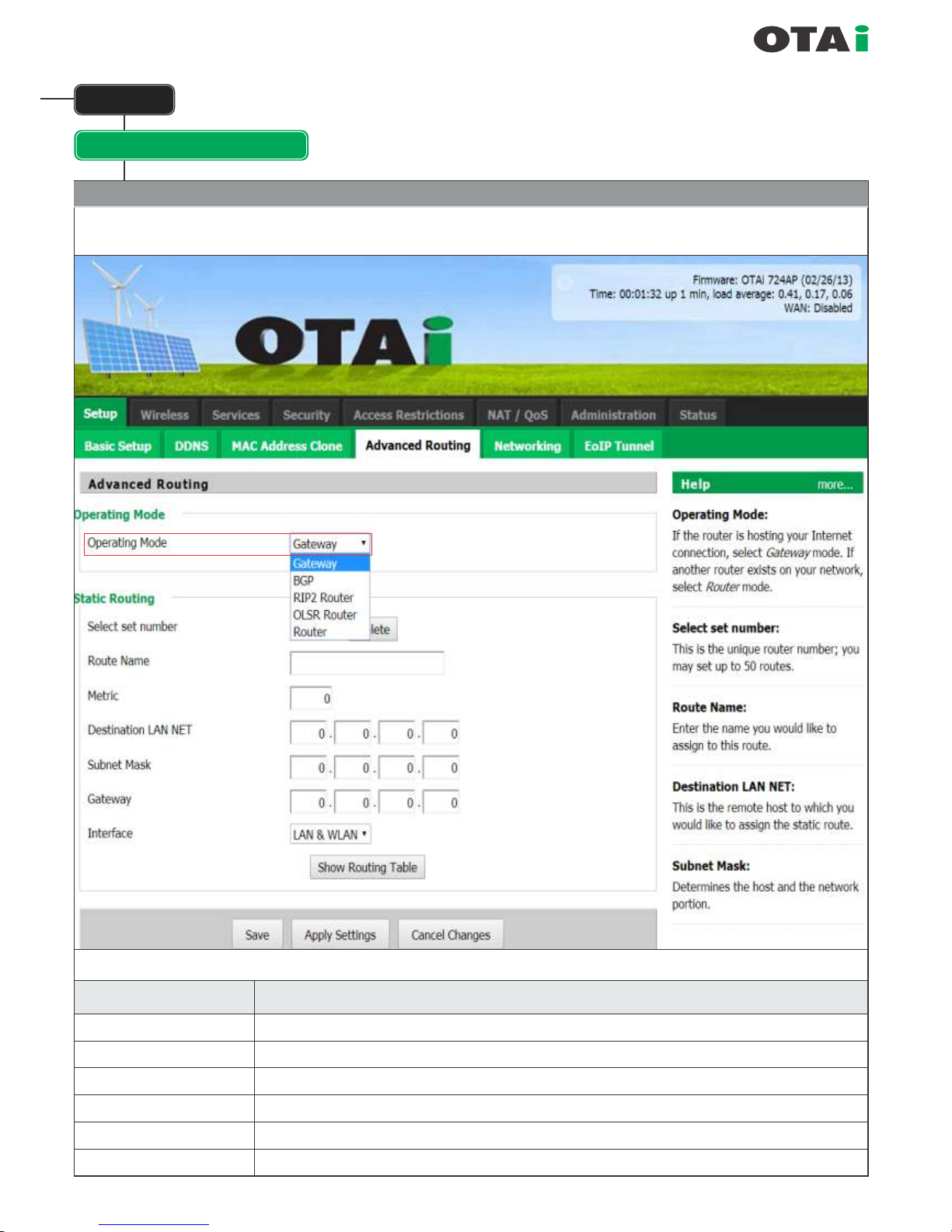
Setup
Advanced Routing
The section allows the user to make the unit act like a router.
Operating Mode
Modus
Description
Gateway
BGP
Rip2 Router
OSPF Router
OLSR Router
Router
Default, Gateway operation mode
BGP-Routing operation mode
Rip2-Routing operation mode
OSPF-Routing operation mode
OLSR-Routing operation mode
"common" Router operation mode
always innovative
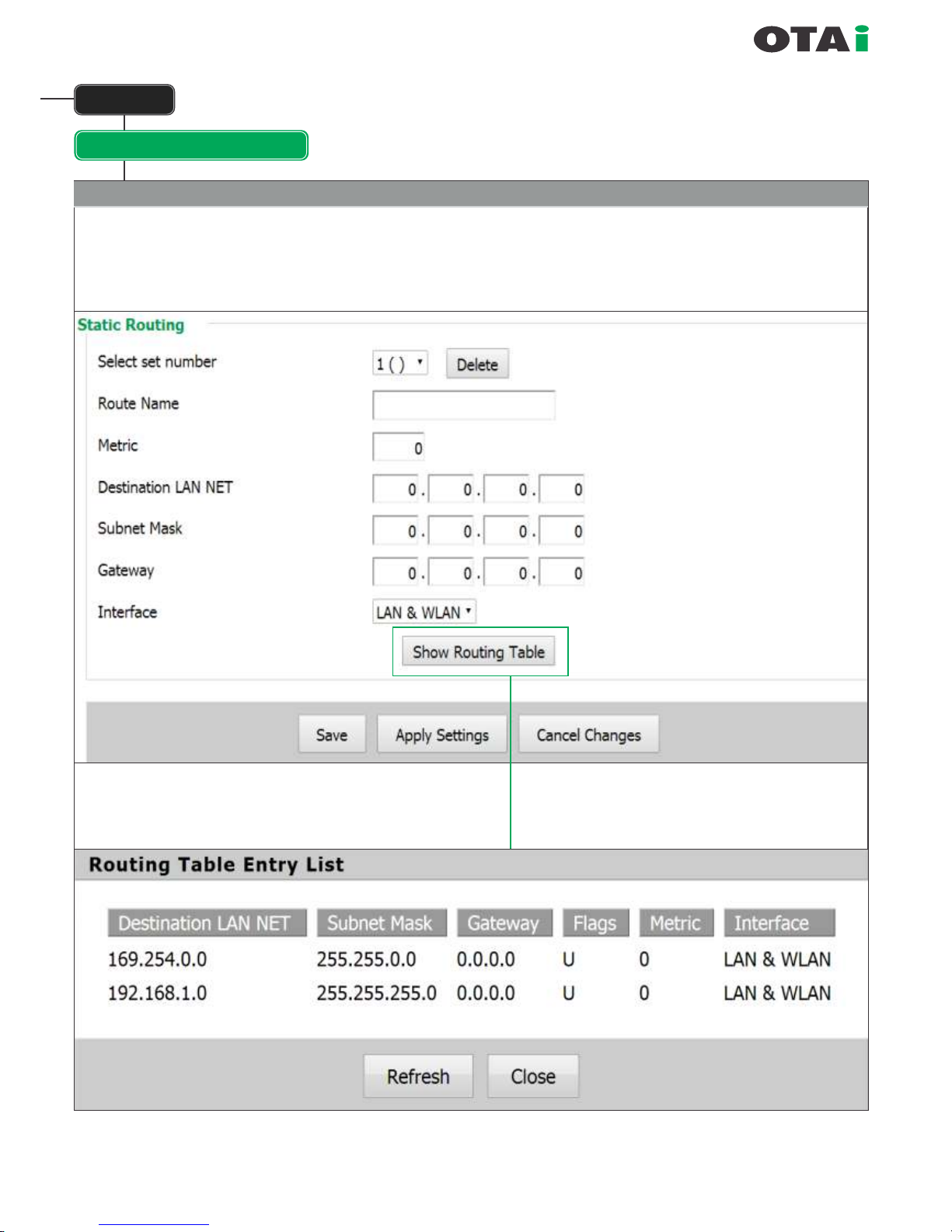
Setup
Advanced Routing
Static Routing
With the "Static Routing" settings you can add static routes. The input parameters are equivalent
to the parameters of the Linux command "route".
always innovative
Setup
Networking
always innovative
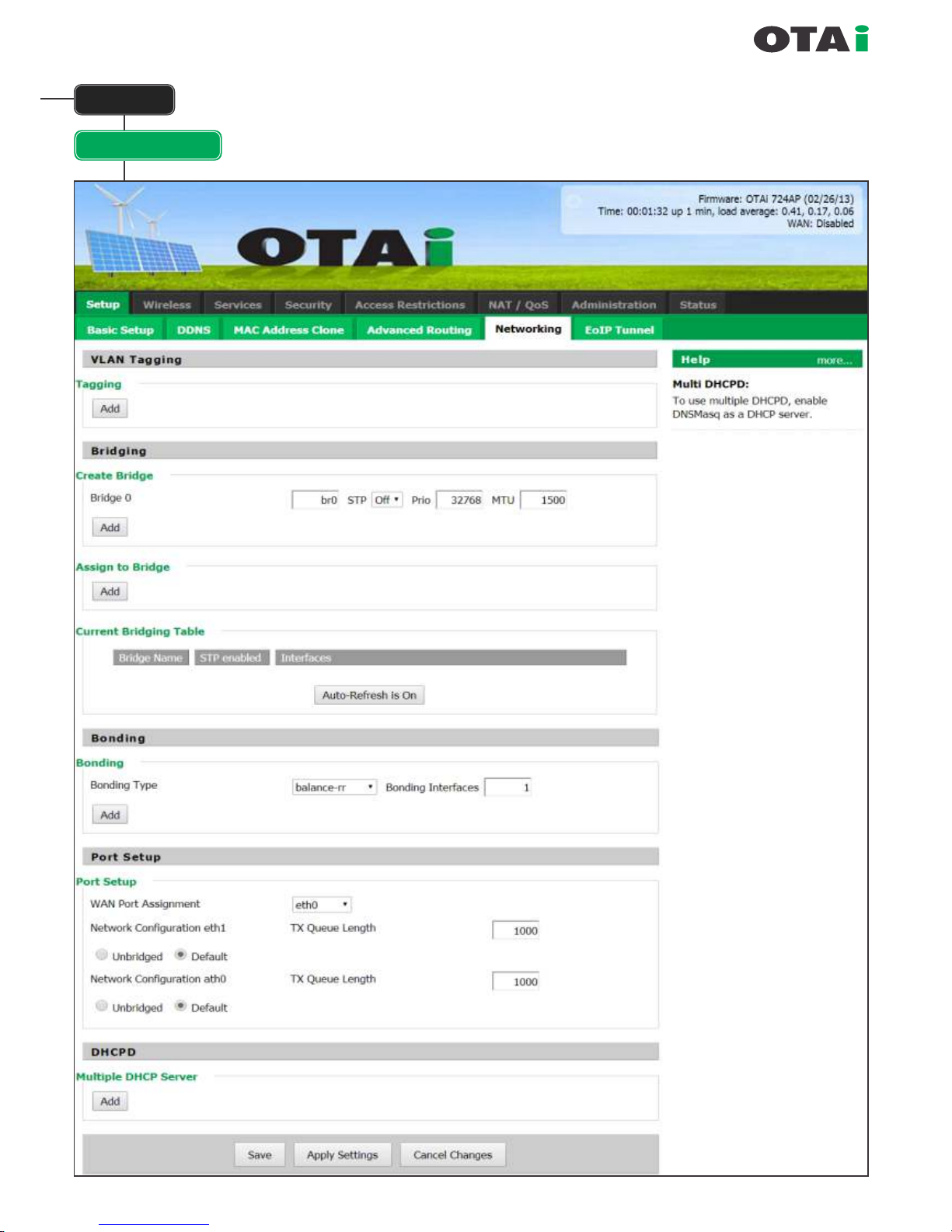
Setup
Networking
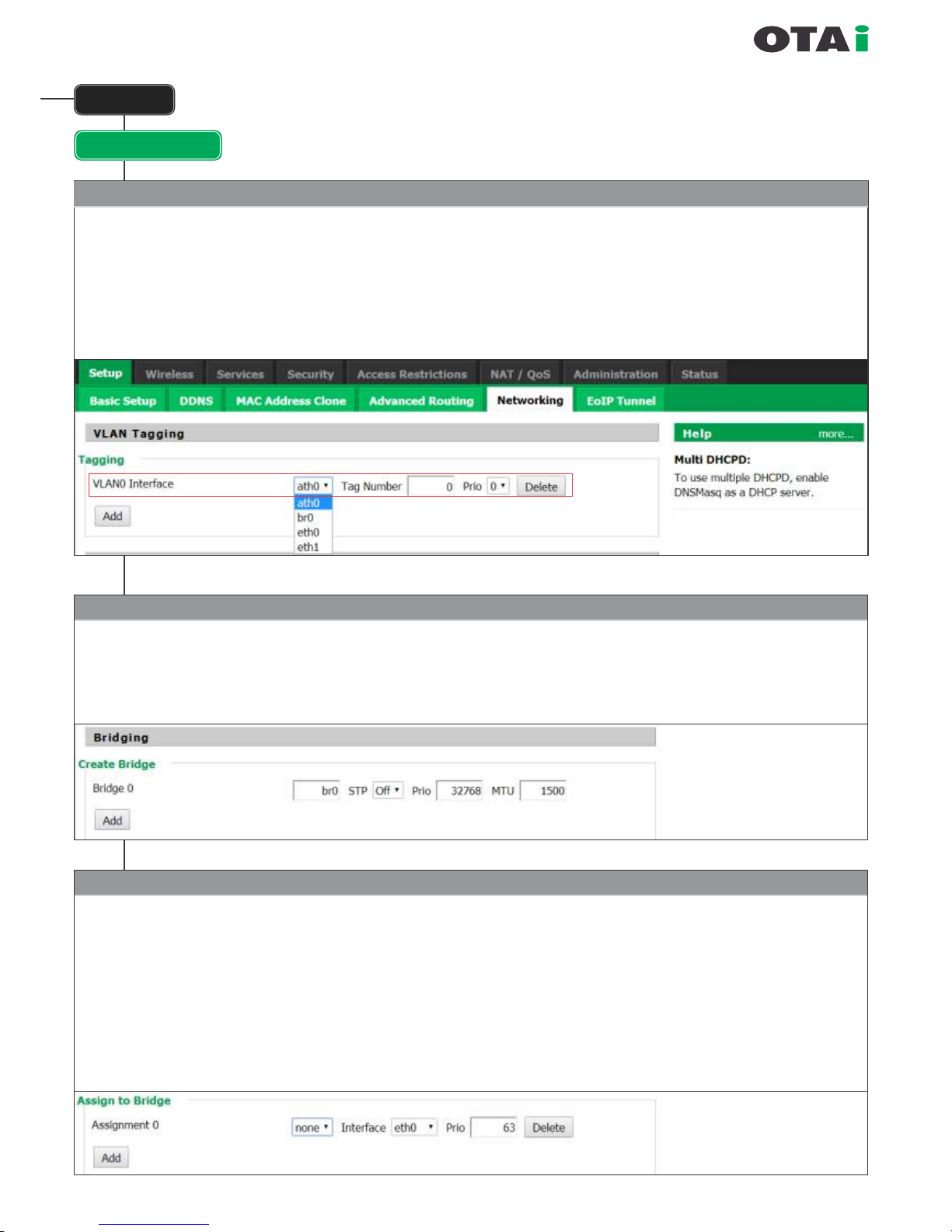
VLAN Tagging
For adding or deleting VLAN Tagging keep on adding VLAN and on choose on which interface it needs to be added and
what would be the TAG number.
Each time its done, please do not forget to do SAVE and when done APPLY for nal applying.
This section allows the user to add VLAN, create additional bridge, add interface to existing bridge and also allow
multiple DHCP servers. In special OTAi models its also allows the user to do BONDING.
Briding
Used to create more bridges. By default the unit has a mother bridge called BR0.
More bridges can be created by clicking on ADD.
Name of the bridge needs to added. Recommended is br1 onwards. STP enabled or disabled can be chosen. By default it is ON.
Priority is also need not be changed.
Assign to Bridge
This allows adding new interfaces to new or old bridges. If an interface already a part of any bridge is added t o another
bridge then it automatically deletes itself f rom the older bridge.
The bridge to work on can be chosen and interface that needs to be added can also be chosen.
Note : If the Wireless is un-bridged then it will not be seen the BR0 table and should rst be bridged if it needs to be added to
another bridge. The VLAN created are all available in the Interface list, if they are not then VLAN were not properly added.
IMPORTANT : In Some INDOOR devices the LAN ports are named as VLAN1 and VLAN2. Here care should be taken that
any new VLAN port added should not be named VLAN1and VLAN2. Also its advisable that VLAN are named as per their TAG
no for easier understanding.
IMPORTANT
If a bridge is added then after
SAVE an APPLY Setting
needs to be done so that the new
bridge is visible in the
Current Bridging Table.
always innovative
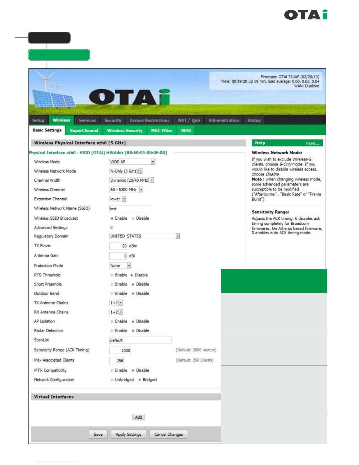
Wireless
Basic Setting
Tx Power : This is the Tx power of the unit.
It is model dependant and
mostly it should be set to 20.
For more information on your
model and the TX powers
supported please contact your
dealer or OTAi support.
Antenna : If country settings are used
Gain then entering the antenna gain
keeps the unit under the EIRP
limits.
This section allows conguration of all
Wireless Parameters
Super Channel : Option of Enable and
Disable available.
(This feature is model dependant and may
not be available in Indoor units)
Disable : Country is available and can
chosen from the list. This
allows the usage of the unit as
per regulatory of the specied
country.

always innovative
Wireless
Basic Setting
Wireless Mode
These parameter is used to dene the operating mode of the Wireless LAN interface.
You can select among the following modes:
Modes
Description
AP
Client
Standard AP mode or MASTER mode.
Client mode, available as IEEE 802.11 standards. Should be used in conjunction with
WAN port. One the unit is set to client mode then the WIRELESS become WAN and
the IP for this port needs to be set at WAN section in Basic Setting. Is useful if the unit
is a client and all trafc coming from the wireless needs to be masqueraded. So use this
if Internet comes to the Unit from Wireless side and all LAN trafc needs to access the
internet but also remain behind the rewall.
Client-Bridge
This is client mode but in bridged form. This is useful in some scenarios but it only forwards
its MAC address for the whole network behind the LAN. So some devices which need their
MAC address also forwarded, may not work. Its used mostly in scenarios like BTS-CPE and
CPE has not many computers attached and CPE to CPE communications is required.
Adhoc
This is used for creating MESH network where no one is master and no one is slave and every
one connects to every one and routing is done by OLSR.
WDS Station
This is the most recommended for use in PTP and PTMP scenarios (CPE-CPE communication
over the BTS is not possible in this mode). This is to be used with WDS AP at the central site.
It offers the most transparent bridging.
 Loading...