

OSTBERG HERU 400–2400T, HERU 400–2400 S User Manual
U S E R M A N U A L | E N
H E R U 400- 2400 T / S
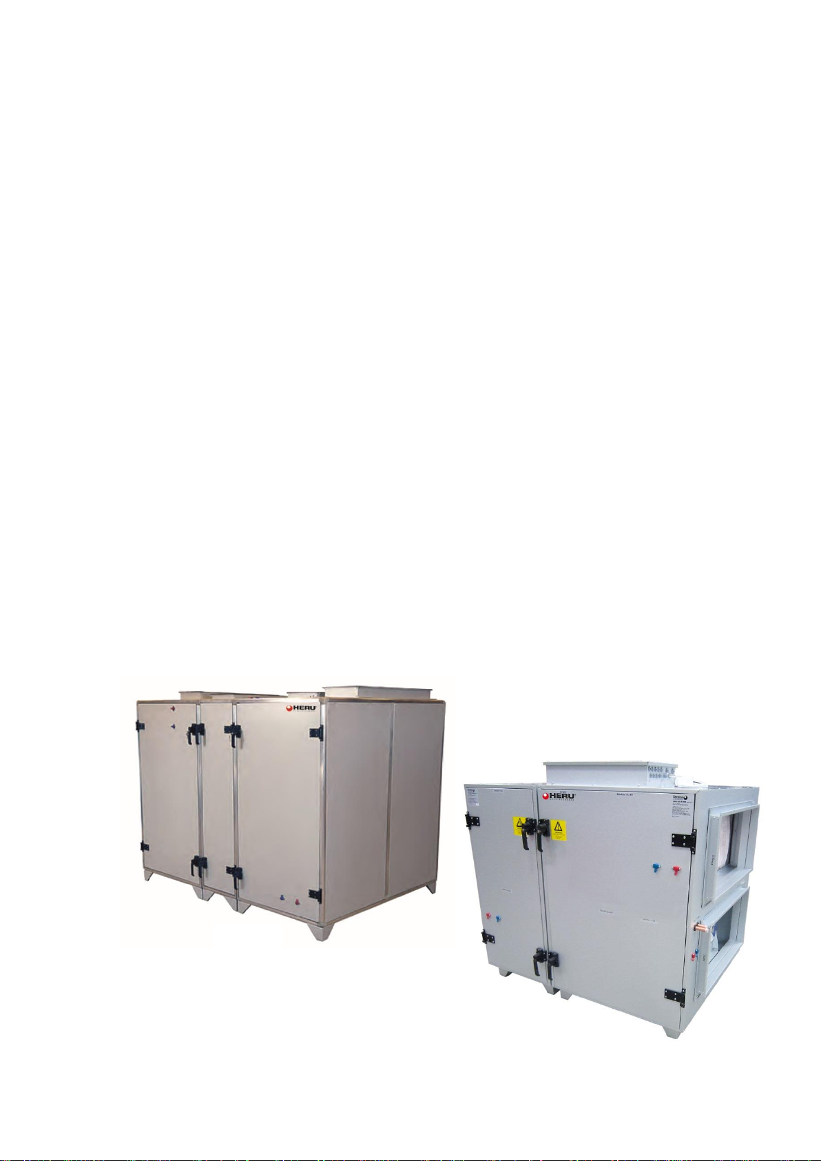
HERU T
HERU S


3 / 120
2017-11-03 Climatix HERU® 200-400
WARRANTY
Warranty period valid according to purchase contract calculated from date of
purchase. Unless otherwise agreed, the usual warranty period is two (2) years in
accordance with NL01, amendment VU03.
SCOPE OF WARRANTY
The warranty covers faults occurring during the warranty period which are reported
to the retailer, or which have been confirmed by H. Östberg AB (the warrantor) or the
warrantor’s representative, and which concern design, manufacturing or material
faults and consequential faults that have occurred on the product itself. The abovementioned faults will be rectified so that the product is made operational.
GENERAL
WARRANTY LIMITATIONS
The warrantor’s responsibility is limited in accordance with these warranty terms and
the warranty does not cover property damage or personal injury. Verbal promises
made in addition to this warranty agreement are not binding for the warrantor.
WARRANTY LIMITATIONS
This warranty applies on condition that the product is used in a normal fashion or
under comparable circumstances for its intended purpose and that the instructions
for use are followed.
This warranty does not cover faults caused by:
– Transport of the product.
– Careless use or overstraining of the product.
– Failure on the part of the user to follow instructions concerning installation, use,
maintenance, care and handling.
– Incorrect installation or incorrect positioning of the product.
– Conditions that are not due to the warrantor, e.g. excessive voltage variations,
lightning, fire and other accidents.
– Repair, maintenance or design changes made by an unauthorized party.
– Faults that do not impact operation, e.g. surface scratches.
– Parts that through handling or normal wear are exposed to greater than average
hazard, e.g. lamps, glass, ceramic, paper and plastic parts, and filters and fuses are not
covered by the warranty.
– Settings; information on use, care, handling, service or cleaning that are customarily
described in the instructions for use; or works caused by the user neglecting to
observe warning or installation instructions; or investigation of such are not covered
by the warranty.
– The warrantor is only responsible for the function if approved accessories are used.
– The warranty does not cover product faults caused by accessories/equipment from
another manufacturer.
Deviations from the unit’s factory settings must be documented in the enclosed
delivery/commissioning report (see tab 4) to avoid costs for faults, if any. The
warrantor is not liable for costs such as adjustment costs related to the replacement of
fans and control boards in the unit.
SERVICE TERMS DURING THE
WARRANTY PERIOD
In cases where service partners are used, the customer will not be charged for work,
replaced parts, necessary transports or travel costs for repairs covered by the
warranty.
This, however, requires that:
– The warrantor and the service partner agree in advance on appropriate measures.
– The unit is installed and adjusted according to relevant instructions.

4 / 120
Climatix HERU® 400-2400 2017-11-03
– The defective parts are handed over to the service partner for forwarding to the
warrantor.
– Repairs are started and work is carried out during normal working hours. For
urgent repairs or repairs conducted outside normal working hours, the service
partner is entitled to charge for extra costs. However, if the fault may pose a health
risk or cause substantial economic damage, the fault will be repaired immediately at
no extra charge.
– Service vehicles or public modes of transport running on a set timetable may be
used (public modes of transport here do not include boats, aircraft or snow vehicles).
RECTIFICATION MEASURES WHEN A FAULT IS DETECTED
When a fault is detected, the customer must notify this to the retailer. Specify the
product it concerns. The part number and date of manufacture (year and week) is
given on the product label. Describe the fault as accurately as possible and describe
how the fault occurred. For a warranty repair to be performed, the customer must
prove that the warranty is valid by presenting the receipt of purchase. After the
warranty period has expired, warranty claims that have not been made in writing
before the expiration of the warranty period will not be valid. The current terms of
sale at H. Östberg AB otherwise apply.
5 / 120
2017-11-03 Climatix HERU® 400-2400
CONTENTS
1. Scope of assembly/installation instructions ............................................................. 9
2. Important information ........................................................................................... 15
Abbreviations ....................................................................................................................... 15
Reference document ............................................................................................................ 16
3. Flowchart and function descriptions....................................................................... 17
CONTROL DIAGRAM HERU® 400-2400 T/S .......................................................................... 17
4. CONTROL SYSTEM Function description ................................................................. 19
5. Password handling ................................................................................................. 24
6. Control unit HMI-TM .............................................................................................. 25
Functions 25
LCD .......................................................................................................................... 25
Up-▲, Down-▼ and ENTER-√) ............................................................................. 25
Info in ..................................................................................................................... 26
Info іn LED display ................................................................................................... 26
ALARM- ............................................................................................................... 27
ALARM -LED display ............................................................................................. 27
ESC ..................................................................................................................... 27
Connecting HMI ................................................................................................................... 28
Screen layout ....................................................................................................................... 28
Screen...................................................................................................................... 28
Navigation rows ...................................................................................................... 29
Display row ........................................................................................................... 29
Preferences row .................................................................................................... 29
Setting discrete parameter values ........................................................................ 29
Setting analog parameter values .......................................................................... 30
7. Getting started, a few simple steps ........................................................................ 31
Logging in with password ..................................................................................................... 31
Setting date and time ........................................................................................................... 31
Language 32
Alarm handling ..................................................................................................................... 32
Resetting alarms...................................................................................................... 32
Changing setpoints ............................................................................................................... 33
Temperature setpoint ............................................................................................. 34
Fan setpoint ............................................................................................................ 35
Manual control of HERU® CX ............................................................................................... 35
Stopping the unit for service ................................................................................... 36
Manually control HERU® CX .................................................................................... 36
Time switch program ........................................................................................................... 37
Default programming .............................................................................................. 37
Week schedule ........................................................................................................ 37
Programming of the month’s times ........................................................................ 37
Copy the month’s times .......................................................................................... 38
Programming examples of the time switch program in different units ............... 39
8. Connection of mains voltage .................................................................................. 40
Connection of mains voltage ............................................................................................... 40
6 / 120
Climatix HERU® 400-2400 2017-11-03
Unit consumption and output.* .......................................................................................... 41
Heating coil consumption and output. ................................................................................ 41
9. External components basic unit .............................................................................. 42
Temperature sensors ........................................................................................................... 43
Internal temp. sensor ............................................................................................. 43
The supply air temperature sensor ..................................................................................... 43
Room temperature sensor .................................................................................................. 44
Outside temperature sensor ............................................................................................... 46
Damper motors.................................................................................................................... 47
Connection of spring-return motor ........................................................................ 47
Connection On/Off motor ...................................................................................... 47
Shunt group ......................................................................................................................... 49
Connection of actuator and circulation pumps ...................................................... 49
Heating.................................................................................................................... 49
Cooling .................................................................................................................... 50
Frost protection ...................................................................................................... 50
Water heating external, not integrated in HERU® CX ............................................. 50
Electric heating coil .............................................................................................................. 51
Electric heating coil external, not integrated in HERU® CX .................................... 52
Filter monitors ..................................................................................................................... 52
Filter monitor with display ................................................................................... 53
Cooling unit .......................................................................................................................... 54
Combi coil, DX cooler and heat pump ................................................................................. 56
Configuration when integrated heater is a water heater..................................... 56
Configuration when integrated heater is an electric heater: ............................... 57
Control inputs Timer etc. ..................................................................................................... 57
Timer control, make: Schneider Electric ............................................................... 57
Timer control, make: Siemens KOP5 .................................................................... 58
Presence detector ................................................................................................ 59
External control from BMS, multiple speeds. ....................................................... 60
Quick stop ............................................................................................................. 61
Indications for external signals ............................................................................................ 61
Operation indication............................................................................................. 61
Alarm indication ................................................................................................... 61
AUX operation indication ..................................................................................... 62
Room unit 2-wire ................................................................................................................. 63
External HMI-DM (IP31) ....................................................................................................... 64
10. Modbus pressure sensor for pressure regulation .................................................. 67
The pressure sensor’s designations and measuring ranges ................................................ 67
Pressure sensor QBM68.xxx ................................................................................................ 67
Settings and connections...................................................................................... 67
Assembly .............................................................................................................. 68
Pressure regulation, addressing of pressure sensor............................................. 68
11. Expansion module with outer components.......................................................... 70
Pressure sensor.................................................................................................................... 70
Flow display/flow regulation ............................................................................................... 72
DX cooling 73
Air quality sensor CO2 .......................................................................................................... 75
7 / 120
2017-11-03 Climatix HERU® 400-2400
Humidity sensor ................................................................................................................... 75
External setpoint .................................................................................................................. 76
Alarm input heating/cooling ................................................................................................ 77
12. Miscellaneous ...................................................................................................... 79
Rotary heat exchanger control unit ..................................................................................... 79
Connection diagram .............................................................................................. 79
Functions ............................................................................................................... 80
Operation indication in the control unit ............................................................... 80
Time switch program ........................................................................................................... 81
General ................................................................................................................. 81
Week schedule ...................................................................................................... 81
Day schedule ......................................................................................................... 82
Calendar (exception and fix off) ............................................................................ 82
Configuration ....................................................................................................................... 83
Communication .................................................................................................................... 85
General ................................................................................................................. 85
MODBUS ............................................................................................................... 86
Initiation of internal MODBUS interface............................................................. 86
Checking IO configuration .................................................................................................... 88
Unconfigured IOs ................................................................................................ 88
Double-configured IOs ........................................................................................ 88
HERU® CX I/O configuration ............................................................................... 91
HERU address list Modbus master ..................................................................... 92
Program versions ................................................................................................................. 92
BSP and application in the controller ................................................................. 92
BSP in HMI .......................................................................................................... 92
Alarm handling ..................................................................................................................... 94
Alarm button function ........................................................................................ 95
Procedure for non-saving alarms........................................................................ 95
Procedure for saving alarms: .............................................................................. 96
Alarm list information ......................................................................................... 96
Menu structure .................................................................................................................... 97
Menu overview ................................................................................................... 97
Start page > Main index > Unit ........................................................................... 98
Start page > Main index > System overview ....................................................... 99
Start page > Main index > Configuration ............................................................ 99
13. SERVICE HERU® .................................................................................................. 100
Service interval ................................................................................................................... 100
Service 100
Damper 101
Duct cooling coil ................................................................................................................. 102
Electric heater .................................................................................................................... 103
Fans 105
Function 105
Check 105
Correct as necessary. ......................................................................................................... 105
Filter 107
Function 107

8 / 120
Climatix HERU® 400-2400 2017-11-03
Check 107
Corrective action ............................................................................................................... 107
Rotary heat exchanger ....................................................................................................... 108
Function 108
Check 108
Corrective action ............................................................................................................... 108
Heating coil ........................................................................................................................ 110
Function 110
Check 110
Corrective action ............................................................................................................... 110
Pull out the coil. ................................................................................................................. 110
14. Accessories ......................................................................................................... 112
Accessory 112
15. Spare parts list .................................................................................................... 113
16. Troubleshooting ................................................................................................. 114
9 / 120
2018-02-13 Climatix HERU® 400-2400
Scope of assembly/installation instructions
1. Scope of assembly/installation instructions
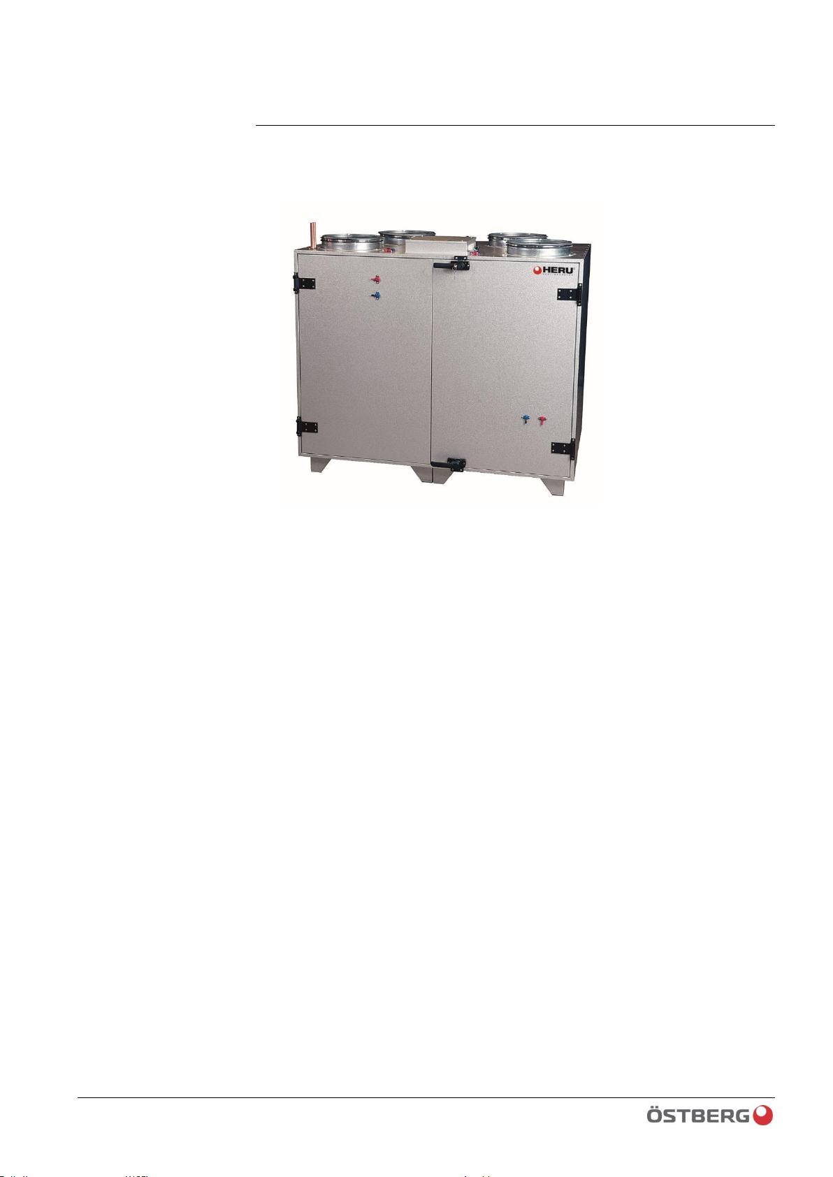
HERU® 400 – 2400 T/S
DESCRIPTION OF UNIT
DESCRIPTION OF UNIT
• The HERU 400-2400 T/S energy recovery unit is designed for supply air and extract air
ventilation with cooling and heat recovery. The unit is equipped with plug fans with
maintenance-free EC motors and integrated heating function via water or electricity. A
large number of optional accessories are available for the unit, such as U pipes, shunts,
dampers, silencers, duct cooling coil, etc. The unit panels are made of double sheet steel
with 50 mm thick mineral wool insulation. HERU 400 T/S, 600 T/S, 800 S and 1200 S
have a steel design with minimized thermal bridges. HERU 800 T, 1200 T, 1600 T/S and
2400 T/S have an aluminium frame and hatch design.
• HERU can be used in environments with stringent demands for:
– high temperature efficiency
– low energy consumption
– low noise level
– high operating reliability
• HERU
•– is equipped with a non-hygroscopic, aluminium rotary heat exchanger located in
the centre of the unit. The heat exchanger has a temperature efficiency rate of up to
86%.
– is designed for simple installation, maintenance and cleaning.
– is supplied with the Siemens Climatix control system as standard. The unit is also
available without a control system.
– can be equipped with an integrated electric heater.
– is supplied with an incinerable F7 bag filter as standard.
– is equipped with wired control unit for operation and monitoring.
– can handle Modbus communication via RS485 and TCP IP.
– is supplied with integrated web server.

10 / 120
Climatix HERU® 400-2400 2018-02-13
Scope of assembly/installation instructions
•HERU is suitable for placement in warm areas.
INSTALLATION AND SAFETY
USE
• For optimal indoor climate and to avoid moisture damage in the property, there must be
continuous and adequate air exchange. The unit must be run continuously and only
stopped for service. Airflow is controlled via various settings on the control panel:
Reduced – Reduced airflow, can be used when no one is in the property.
Normal – This is set by the installer and should not be changed by the user.
Boost – Higher airflow than normal, medium/max can be selected. This should be used
when the load on the property is higher than what the standard mode is set for, e.g. when
there are more people than normal in the property.
• When installing HERU®, follow applicable regulatory requirements and
recommendations concerning location, access, duct insulation, etc.
• The user may, in accordance with IEC 60335-2-40, independently perform the service
and maintenance on Heru that is described in this user manual. However, the unit must be
disconnected from any power supply before all such work. With reservation according to
IEC 60335-2-7.12 “This appliance is not intended for use by persons (including children)
with reduced physical, sensory or mental capabilities, or lack of experience and
knowledge, unless they have been given supervision or instruction concerning use of the
appliance by a person responsible for their safety. Children should be supervised to ensure
that they do not play with the appliance.”
• HERU® should be kept in a sheltered and dry environment during storage before
installation.
• Dimensioned airflow should not exceed 75% of the unit’s maximum capacity.
• Check regularly to ensure that supply air and extract air are functioning properly.
• To avoid condensation in the unit in cold weather, the unit should not be turned off for a
prolonged period of time. If the unit is installed during cold weather and not operated
immediately, the ducts should be plugged to prevent condensation.
SAFETY
• Maintenance and operation of the unit may only be performed by personnel who have the
requisite knowledge concerning maintenance of the ventilation unit and who have read this
manual.
• Take into account the unit’s weight when installing. See technical specification for
weight data.
• Bear in mind that HERU® and the fan housing may have sharp corners and edges.
• Before commissioning, make sure there are no foreign objects inside the unit which could
cause serious injury or damage to the unit.
• Always follow the electrical safety regulations concerning free clearance for control
cabinets and electric heating coils.
• Make sure that the unit is always locked and that the keys are stored in a location that is not
accessible to unauthorized persons.
• Do not open the service doors while the unit is in operation. Overpressure from the fans
could cause the doors to swing open.
• The unit should be fitted with a locking safety switch placed nearby.
• Turn off the unit via the control panel and wait two (2) minutes before opening the service
doors.
• The safety switches must be switched off and locked before starting any service
work.

11 / 120
2018-02-13 Climatix HERU® 400-2400
Scope of assembly/installation instructions
• Do not use the safety switches for normal start and stop of the unit.
• Electrical installation, electrical and mechanical work and work inside the unit and its
peripheral equipment may only be performed by certified electricians or personnel
designated by H. Östberg AB.
• Note that the surfaces of the unit may be cold in winter conditions.
• HERU® contains rotating parts that could cause serious injury in the event of contact. The
unit must therefore be connected to a duct, the doors closed and locked and the key
removed.
• The heating coil in the unit could cause burns. The heating coil may still be hot after the
voltage has been switched off for service, maintenance and repair work (approx. 60o).

12 / 120
Climatix HERU® 400-2400 2018-02-13
Scope of assembly/installation instructions
ASSEMBLY AND INSTALLATION INSTRUCTIONS HERU®
400-2400 T/S
The base of the HERU T/S unit must be even and stable. Note and take into account the
unit’s weight.
1. Always lift the unit using a pallet jack or truck with forks at least as long as the width of
the unit.
2. Use a spirit level to make sure that the unit is level. Use the adjustable feet if the floor is
too uneven for level installation of the unit. A Novibra mat should be placed under the feet
to reduce vibrations against the floor joists.
3. Connect the ducts. NOTE: Make sure to connect the correct
supply/extract/exhaust/outside air connections to the correct ducts. Duct connections
should be performed using duct clips or sleeves with surrounding insulation.
4. Insulate the ducts. The ducts should be insulated all the way to the unit casing.
- Supply air ducts and extract air ducts should be heat insulated if the unit is placed in a
cold area.
- Extract air ducts should also be insulated against condensation if installed in warm
areas with low air supply temperatures.
- Outside air ducts and exhaust air ducts should always be insulated against
condensation.
5. If a heating coil is connected, a motor-driven, spring-return damper actuator should be
installed in the outside air duct.
6. Connect the electrical cables as shown in the wiring diagram.
7. The GT1 duct sensor must always be installed inside the supply air duct and connected
to the unit. See chapter 9.2, Supply air temperature sensor.
8. Ensure that there is free clearance in front of and above the unit according to the
recommended service clearance.
9. The duct cooling coil must always lean slightly toward the drainage connection to help
avoid the risk of stagnant water.
10. Locking safety switches should be placed near the unit (not supplied by H. Östberg
AB).
HERU 400 and 600 T/S are supplied in one part.
HERU 800 and 1200 T/S are supplied in two parts. Screw the unit together using the
fixed internal corner joints (rear) and the posts’ corner angles (front). Use the duct
connection to access the corner at the far end.
HERU 1600 and 2400 T/S are supplied in three parts. In the rear corner, use the
threaded rod to pull the pieces together and tighten using the supplied nut.
13 / 120
2018-02-13 Climatix HERU® 400-2400
Scope of assembly/installation instructions
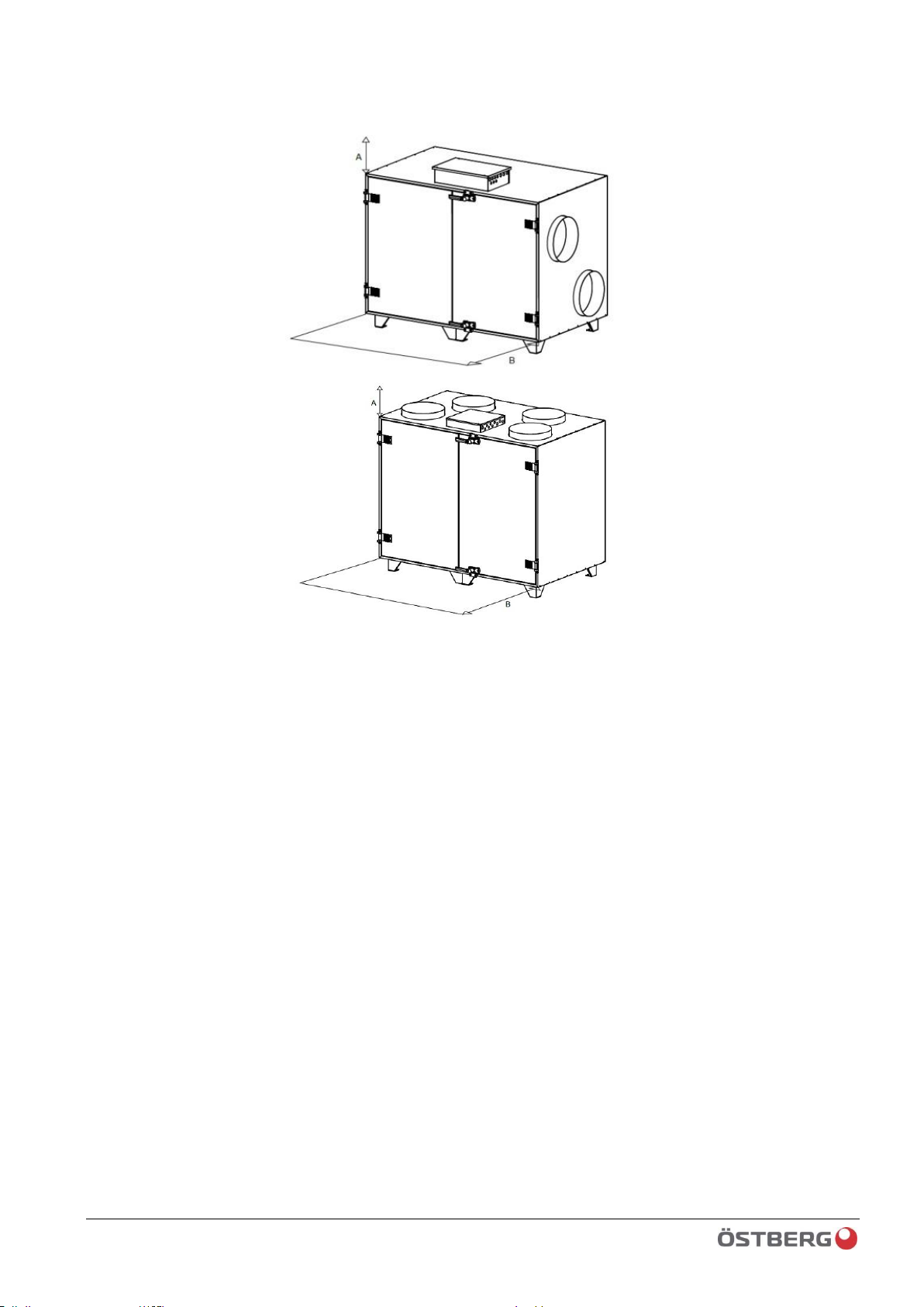
FREE CLEARANCE FOR SERVICE AND OVERHAUL
HERU T/S
A=500 mm B=1200 m
BEFORE STARTING
- Ensure that HERU® is correctly installed.
- Make sure that all ducts, water pipes and electrical connections are correctly
assembled.
- Make sure no objects or dirt have entered the unit during construction, as this could
lead to injury and/or damage to the unit. Make sure that service doors are closed and
locked.
- Make sure that the connection cable has not been damaged during assembly and
installation.
STARTING
Carefully read the operating instructions before starting up the unit.
• HERU® will start automatically (after a few minutes’ delay) when the power is
turned on. In the event of a power failure, always check to make sure that the unit
starts up.
• NOTE: Never run the unit without a filter!

14 / 120
Climatix HERU® 400-2400 2018-02-13
Scope of assembly/installation instructions
15 / 120
2018-02-13 Climatix HERU® 400-2400
Important information
2. Important information
Information is provided for each individual function on the menu in the control unit/HMI.
Because of this, the information in the example menu screenshots may not be consistent
with the information provided in the HMI of each individual HERU® CX unit. Sometimes all
of the rows of information are described, when in reality only a limited number of menu
rows will be visible. The reason for this is that, to simplify handling for the user, nonselected functions and settings are “turned off” at configuration. If any information is not
provided in the display, that function or input is probably not configured/enabled. See 0
for more information.
This document describes general functions and components that are directly connected to
the HERU® CX unit.
The software may include functions and concepts related to moisture, humidification
and/or dehumidification. All such information has been omitted in this document. H.
Östberg AB does not accept any responsibility for these functions, as it is not our intention
to treat air using humidification or dehumidification.
The software is continuously developed and improved, and therefore H. Östberg AB shall
not be held accountable for any discrepancies that may appear in this document, and also
reserves the right to modify data and design.
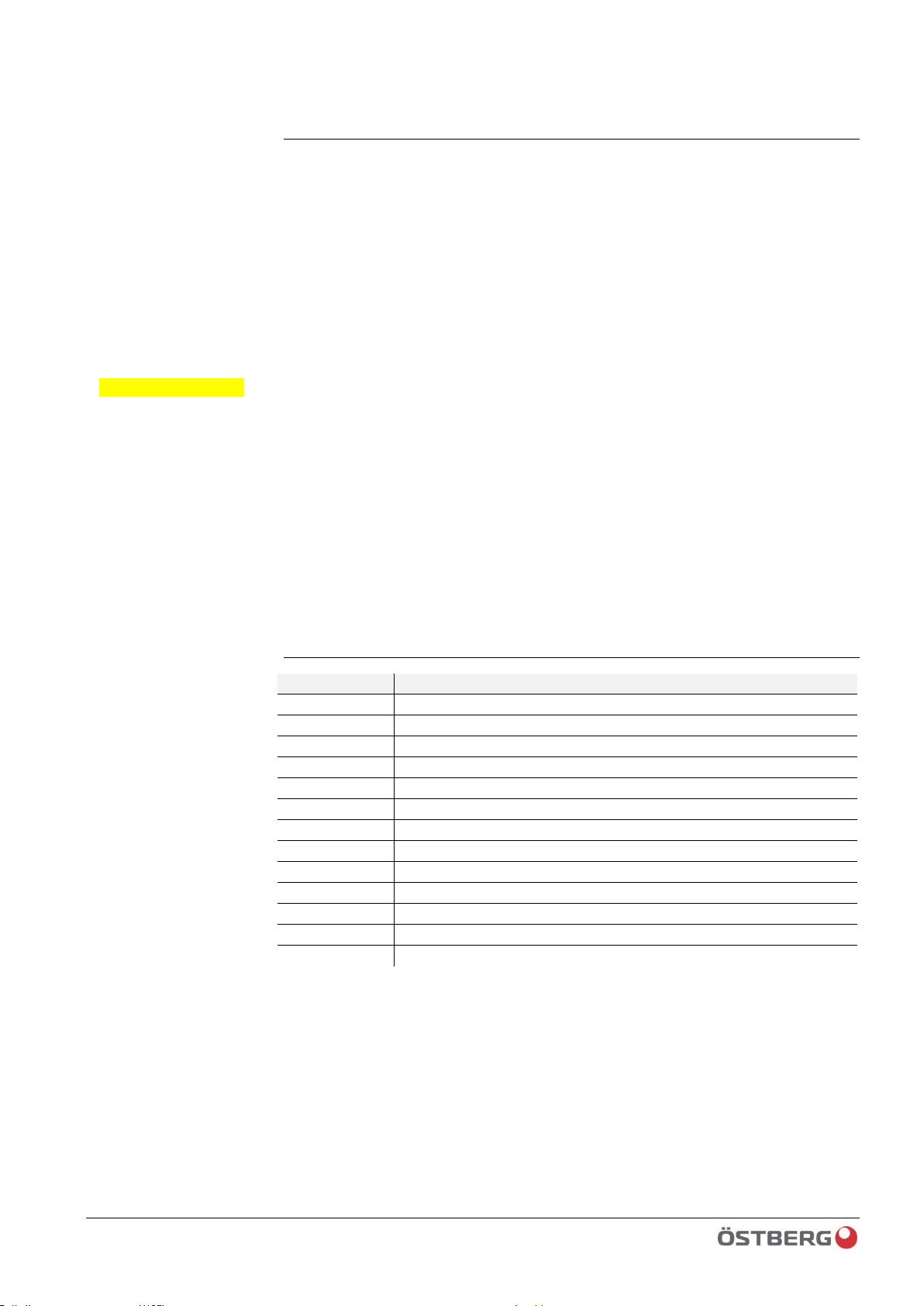
Abbreviations
Abbreviation
Explanation
BMS
Building Management System (parent control system)
BSP
Board Support Package (firmware)
EXP1
Expansion module 1, module for multiple outlets and inlets
EHC
Electric Heating Coil (electric air heater)
HERU® S CX
HERU® Side-connected unit with Climatix control
HERU® T CX
HERU® Top-connected unit with Climatix control
HERU® CX
HERU® unit with Climatix control (data applies to both S & T)
HMI
Human Machine Interface (control panel)
LED
Light Emitting Diode (light diode for indication)
NC
Normally Closed (opening switch at signal)
NO
Normally Open (closing switch at signal)
OEM
Original Equipment Manufacturer
PROC1
Processing unit 1 (Climatix base unit)
Important!
16 / 120
Climatix HERU® 400-2400 2018-02-13
Important information
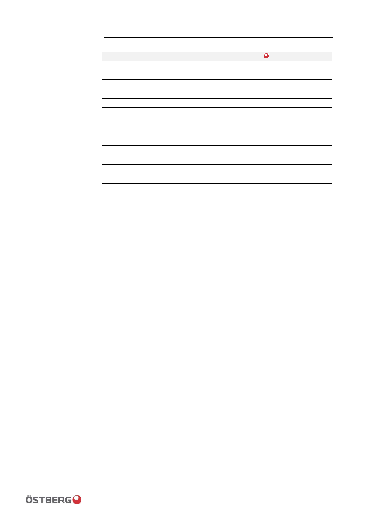
Reference document
Document title
Document no.
Climatix Room unit POL822.60 (2-wire interface)
9720001
Climatix Basic Documentation
9720005
Climatix Modbus Guide & Reference List
9720006
Climatix LON Guide & SNVT List
9720007
Climatix BACnet/IP Guide & Object List
9720008
Climatix OPC Guide & Tag List
9720009
Climatix Advanced Web Module Guide
9720010
Climatix Modbus Pressure Sensor QBM68
9720014
Wiring diagram HERU® 400-600 T/S
9500003
Wiring diagram HERU® 800-1200 T/S
9500002
Wiring diagram HERU® 1600-2400 T
9500001
Wiring diagram HERU® 1600-2400 S
9500007
Wiring diagram HERU® CX-EXP1
999050054
The referenced documentation is digital and available at www.ostbergs.com
17 / 120
2018-02-13 Climatix HERU® 400-2400
Flowchart and function descriptions
3. Flowchart and function descriptions
The flowchart and function descriptions describe most of the functions the controller can
handle. With regards to unit configuration, all functions may not be available in the
supplied model. Some can be selected in the HMI and are then described as Optional in
the HMI. Other functions do not have the external components required for selection. If
you have any questions about a specific function, please contact your nearest H. Östberg
AB sales office for assistance. The controller supplier constantly works with product
development and we reserve the right to continuously improve our product. As such,
there may be new functions in the software version this unit is equipped with, even if this
function is not described in the function description.
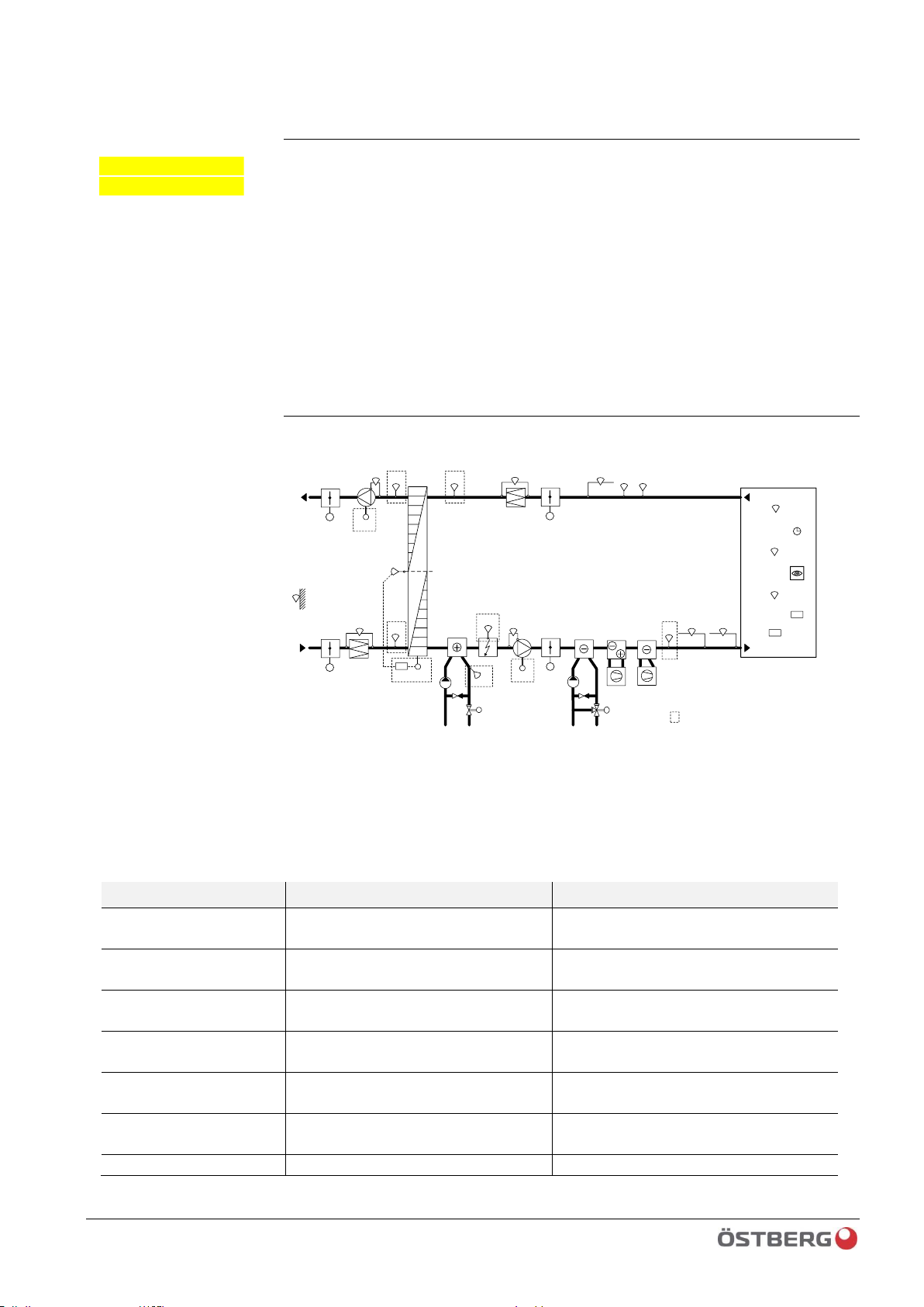
CONTROL DIAGRAM HERU® 400-2400 T/S
GT3
EMS-RV
GT1
GT42 GT2
FF-EC
EMS-M
TF-EC
RU1
TU1
ÖSTBERG HERU®CX
GP5
-
+
GTR
TM1
GN1
Cooling
water
CP2
SV2
GP3
SV1
CP1
GT8
Heating
Water
ELB
GT9
GTU
GF2
GQ1
GM1
GM1GQ1
DX-C
DX-CHP
GP2
-
+
GP1
-
+
GP4
-
+
-
+
GF1
EMS
ST1
ST2
ST2
ST1
= included in standard HERU® CX
The unit comes standard with: Filter, fans, heat exchanger, water/electric heater, EMS, EMS RV, GT1, GT2, GT3,
GT42 and GT8/GT9. Other components are optional.
ID
Description
ID
Description
ID
Description
GT1
Supply air temp.
sensor
GP5
(Pressure switch/flow detector)
ELB
DX-C
DX-cooling 1…3 stage
GT2
Extract air temp.
sensor
GF1
Supply air flow
DX-CHP
Direct expansion cooling and heating
pump (or Water)
GT3
Outside air temp.
sensor
GF2
Extract air flow
GQ1
CO2 sensor, room or extract air
GT42
Exhaust air temp.
sensor
ST1
Damper actuator supply/outside
air
GM1
Humidity sensor, room or extract air
GT8
Frost temp. sensor
ST2
Damper actuator
extract/exhaust air
GN1
Presence detector
GT9
Over-temp sensor
EMS
Speed control rotary heat
exchanger
TM1
Timer OT/Boost
GTR
Room temp sensor
EMS-M
Drive motor EMS
TU1
Setpoint impact room pot.
Important
information
Climatix HERU® 400-2400 2018-02-13
GTU
Outside temp sensor
EMS-RV
Rotation monitor EMS
RU1
Room unit
GP1
Supply air pressure
sensor
CP1
Circulation pump heating
Supply-EC
Supply air fan (TF) EC motor
GP2
Extract air pressure
sensor
CP2
Circulation pump cooling
ExtractEC
Extract air fan (FF) EC motor
GP3
Supply air filter sensor
SV1
Valve actuator heating
GP4
Extract air filter sensor
SV2
Valve actuator cooling
TEMPERATURE REGULATION
The temperature can be regulated as constant supply air regulation or room
regulation/extract air regulation. With constant supply air regulation, the air supply
temperature remains constant. With room regulation, a sensor is placed in the room
to obtain a constant room temperature (suitable when a cooling coil is installed).
Extract air regulation works in a similar way, but with the difference that the
temperature is measured on the unit’s
extract air side.
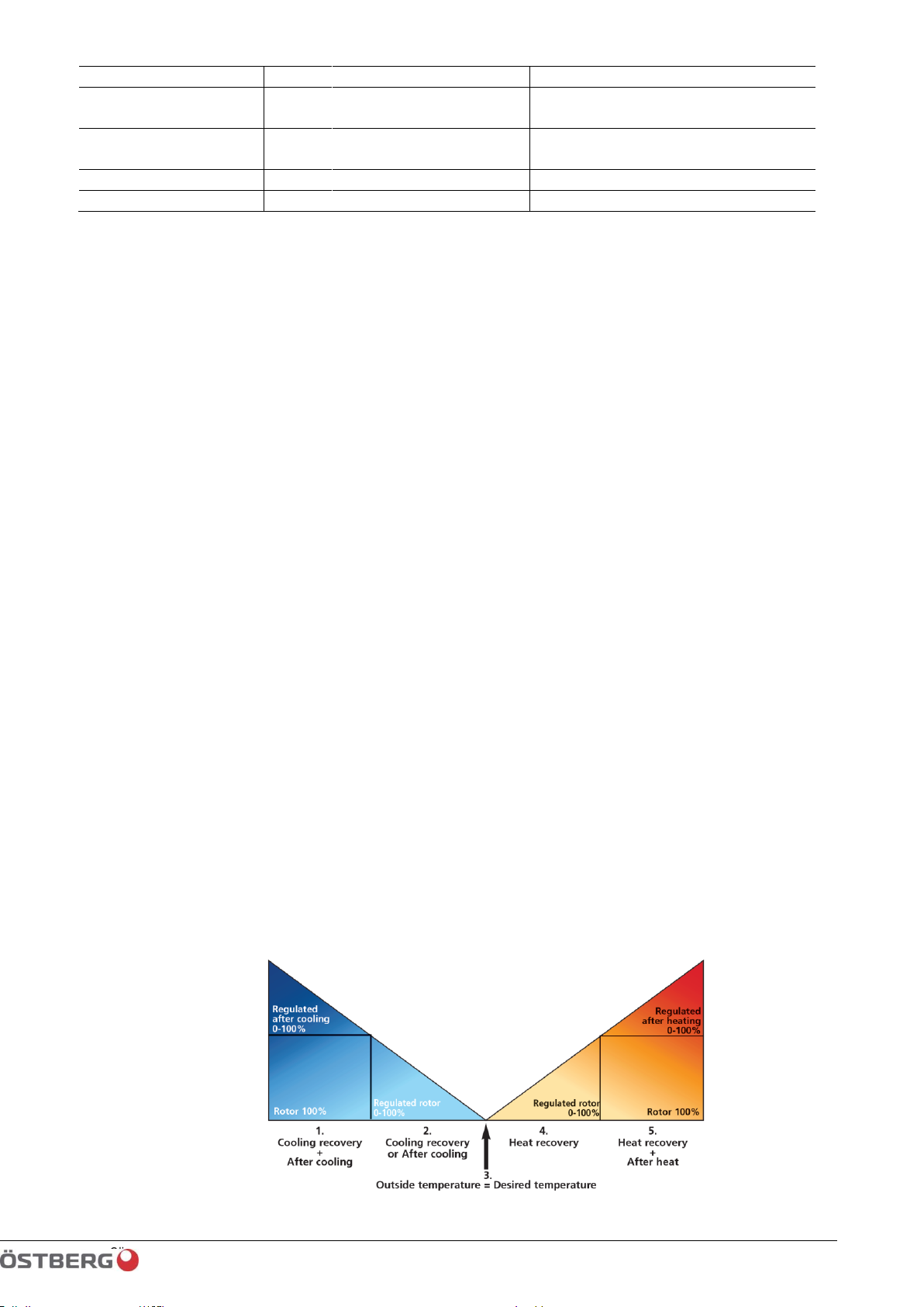
The temperature can be regulated in five stages:
1. Cooling recovery + cooling: The control unit can regulate a cooling coil (e.g.
cooling water from geothermal heating), when the cooling recovery from the rotor is
insufficient.
2. Cooling recovery and/or regulated cool down. The rotary heat exchanger starts
if the extract air temperature is lower than the outside temperature.
• Regulated cool down: If the temperature outside is lower than the desired room
temperature and is not sufficient for lowering the room temperature, cool
down will start.
3. Outside temperature = desired temperature: When the outside temperature is
the same as the desired supply air temperature, the rotor will stop.
4. Heat recovery: The rotary heat exchanger starts to recover the warmer indoor
temperature.
5. Heat recovery + heating: In climate zones in which the rotary heat exchanger, in
spite of its high efficiency, is not sufficient to achieve the desired supply air
temperature, the control unit can also regulate either an electric heater or a heating
coil connected to the duct.
“Night cooling” is a function which utilizes the cool outdoor temperature and cools
down the building at night without using any other additional energy. The fan speed is
boosted when the ratio between the outside temperature and the extract air
temperature is within the programmed criteria.

19 / 120
Climatix HERU® 400-2400 2017-11-03
SERVICE Climatix HERU®
4. CONTROL SYSTEM Function description
CONTROL
Operating times
The unit is controlled via a built-in timing channel.
At start-up, the ST1/ST2 dampers open. After a set time, the extract air fan (FF) starts
and heat recovery (EMS) is controlled to maximum recovery, if the outside
temperature is under the adjustable set value (15°C). The supply air fan (TF) then starts
after an adjustable time delay, and normal regulation starts. When the unit is stopped,
first the fans will stop and then the ST1 and ST2 dampers will close according to the set
time, with control voltage or spring return.
Timer/Boost
The unit is controlled to the set fan stage for prolonged operation or boost during the
set time via push button TM1, push button timer (time in timer) or pulse-controlled
push button (spring return with adjustable time in PROC1).
Circulation pumps
Circulation pump heating CP1 switches on automatically when heating is required or at
outside temperatures below the minimum setting (adjustable in HMI). Exercised once
a week.
Circulation pump cooling CP2 switches on automatically when cooling is required, if
pump is blocked or if outside temperature is lower than minimum value (adjustable in
HMI). Exercised once a week.
Cool down of electric heater
If electric heating is configured and the unit is stopped, the supply air fan will switch
over to prolonged operation to cool down the electric heater. ST1 and ST2 remain
open during cool down.
Rotary heat exchanger
Time-controlled blow-off when the unit is stopped or when heating is not required.
Control is integrated in EMS.
REGULATION
Temperature regulation
The supply air temperature is regulated via GT1.
When the heating requirement increases, temperature is regulated according to the
following sequence:
1. Cooling valve SV2 closes or cooling unit KM1 begins decreasing output.
2. Heat exchanger EMS increases heat recovery if GT2 > GT3.
3. Heating valve SV1 opens for heating, or electric heater EHC begins increasing
output.
For reduced heating requirements/increased cooling requirements, the above
sequence is reversed.
Models with DX cooling and heating pumps and integrated heating:
1. The CHP cooling and heating pump begins decreasing cooling effect.
2. Heat exchanger EMS increases heat recovery if GT2 > GT3.
3. The CHP cooling and heating pump begins increasing heating effect.

20 / 120
Climatix HERU® 400-2400 2018-02-13
CONTROL SYSTEM Function description
4. Heating valve SV1 opens for heating, or electric heater EHC begins increasing
output.
For reduced heating requirements/increased cooling requirements, the above
sequence is reversed.

21 / 120
2018-02-13 Climatix HERU® 400-2400
CONTROL SYSTEM Function description
Extract air regulation (cascade control)
Can be selected in HMI. Temperature sensor GT2 becomes main sensor and
temperature sensor GT1 becomes sensor for supply air limit according to set value in
HMI.
Cascade control in combination with supply air regulation [Ext air SuWi] Selectable in
HMI: switching between extract air regulation and supply air regulation according to
outside temperature or annual calendar, or digital input (summer/winter changeover).
Different setpoints apply for cascade control and supply air regulation.
If room sensor GTR is used, room regulation in combination with supply air is also
selectable [Room SuWi].
Outside-compensated temperature regulation
Selected in HMI. Temperature is shifted via 4 breakpoints, according to adjustable
value, from [start point] to [end point] according to [ΔK] for summer/winter.
Fan compensation (fan boost/fan reduction)
Selected in HMI. Possible to compensate for fan via outside temperature, room
temperature GTR, air quality GQ1 and moisture GM1. All of the different fan
compensations will be added to the total fan compensation value.
Temperature exercise
Used for support heating and/or cooling or night cooling when there is no room
temperature sensor.
Temperature exercise ramps/starts up the unit after an extended period of inactivity
(switched off) and updates the duct sensor’s extract air temperature.
Support operation
Selected in HMI. Selectable heating, cooling or heating & cooling.
Temperature regulation support heating when unit stopped (night time), as follows:
1. Heat exchanger
2. Heating coil in sequence according to specified order.
Support cooling with cooling coil.
Night cooling (summer night cooling)
Selected in HMI. Night cooling starts automatically to cool premises at night with cool
fresh air.
Heat exchanger, heating coil and cooling coil are blocked during night cooling.
Conditions for automatic start:
– Time switch program must be in OFF mode.
– Outside temperature must be higher than MIN outside temperature.
– Outside temperature must be lower than the difference between the room/extract
air temperature.
-(minus) Δ [1K].
– Room/extract air temperature is higher than room/extract air setpoint.
Night cooling is cancelled if the timer input is enabled, or if the above conditions cease
during operation.
PROTECTION
Frost protection
At low return temperature GT8 in the heating coil, the heating valve SV1 will be
overridden (open more than the heating requirement demands), according to set
value in HMI. If the temperature continues to decrease, an alarm will go off and the
unit will stop. When the unit stops, the coil will maintain heat according to set value.
Frost protection sensor is reset in HMI.

22 / 120
Climatix HERU® 400-2400 2018-02-13
CONTROL SYSTEM Function description
Heat exchanger
Rotation monitor RV1 monitors the rotation of the rotary heat exchanger, EMS alarm
goes to HMI.
EMS has a built-in safety disconnection switch. In the event of over-current, an alarm is
sent from the heat exchanger to HMI. The alarm is reset on EMS (by unplugging mains
voltage/ext. switch disconnector) and on HMI. Alarm class selectable in HMI.
EHC
GT9 consists of a low-temperature alarm (automatic return) and a high-temperature
alarm (manual return). If the GT9 alarm is triggered, EHC will be blocked and cool
down will begin. The electric heating alarm can be reset in HMI. If the high
temperature protection has also tripped, GT9 must also be reset on the EHC electric
heater.
In the event of fire/smoke alarm, there will be no cool down of the EHC electric heater.
GP5 monitors minimum supply air flow/pressure. If pressure falls below the set value,
EHC is blocked and the alarm will not be sent.
Efficiency measurement extract air
Temperature efficiency is calculated via temperature sensors GT2, GT42 and GT3,
provided that the heat exchanger signal is 100%.
An alarm will go off if efficiency falls below the set value.
Fire/smoke
When a signal is received from the parent fire/smoke fume system, the fire/smoke
alarm will go off.
In the event of alarm, the following functions can be selected:
The unit is stopped and the damper closes.
• Extract fan speeds up to the fire setpoint and supply fan is stopped. Dampers
ST1/ST2 remain open.
• Supply fan speeds up to the fire setpoint and extract fan is stopped. Dampers
ST1/ST2 remain open.
• Supply + Extract fans speed up to the fire setpoint. Dampers ST1/ST2 remain
open.
ALARM
Deviation alarm: GT1, GT2, GT3, GP1, GP2, GP3, GP4, GF1 AND GF2
Recovery alarm (rotor control EMS)
Fan alarm
frost protection sensor GT8/Overheating electric heater GT9
Low efficiency
Multifunctional input
The following functions are located on the same signal input and cannot be combined.
- Control input 1: Timer input for additional speeds/
- Control input 2: additional speeds from BMS.
- Quick stop input
- Common filter alarm, active via pressure sensor, supplied as optional accessory.
OPTION via add-on module EXP-1 (9050054)
The following functions are optional accessories and are not included in the basic
model supplied by H. Östberg AB.
In addition to the respective sensors, an EXP1 is also required to obtain multiple I/Os
(inputs/outputs).

23 / 120
2018-02-13 Climatix HERU® 400-2400
CONTROL SYSTEM Function description
Pressure regulation
Duct pressure regulation, designed to be combined with VAV systems. The fans are
controlled to maintain a preset pressure (setpoint), via GP1 & GP2, in each duct
system.
Flow regulation
Flow regulation is designed to be used in systems where a constant flow is desired. The
fans are controlled to maintain a preset flow (setpoint), e.g. compensate for increased
filter clogging via GF1 & GF2.
Pressure regulation with flow measurement
This model can also be combined with one fan functioning as MASTER/duct pressure
regulation and the other fan as SLAVE/flow regulated.
Master/slave regulation requires GP1/GP2, GF1 & GF2.
Fan compensation
Fan compensation can be obtained via AIR QUALITY/HUMIDITY SENSOR GQ1/GM1
(duct or room model). The fan can be boosted to a higher flow at higher PPM/RH.
Pump monitoring
Monitoring carried out using current relay and feedback to PROC1. If the pump does
not draw current when the pump is in operation, an alarm will go off and heat
maintenance of the frost protection sensor will take over. Monitoring is possible for
both CP1 and CP2.
Direct expansion cooling unit
Can control 1-STAGE (ON/OFF)/ 2-STAGE stage-connected (50/50 stage)./ 3-STAGE
binary (1/3-2/3 stage).
Alarm from direct expansion cooling or operation indication from direct expansion
(DX) cooling.
Su/Wi switch
Summer-Winter switch, can switch between summer/winter from BMS system or via
supply pipe thermostat at COMBI COIL.

24 / 120
Climatix HERU® 400-2400 2018-02-13
Password handling
5. Password handling
Password protection can be set for up to nine levels. Only three levels are defined in
this application.
The following actions are possible on the different levels:
• Without password:
– Read access to all menus except system parameters, config. and detailed menus.
– Read access to alarm lists and alarm history.
• Password 1000/”User” level 6.
– Same rights as for “without password” plus:
– Read access to all menus except configuration menus.
– Write access to the main setpoints.
– Alarm and alarm history can be acknowledged and reset.
• Password 2000/“Service” level 4:
– Same rights as for “User”, plus:
– Rights for all menus and system settings.
– If you must use password 2000, exercise extreme caution. There is a high risk
that a change may damage basic settings/configurations.
STOP
Warning!
25 / 120
2018-02-13 Climatix HERU® 400-2400
Control unit HMI-TM
6. Control unit HMI-TM
General
HMI-TM is designed as a separate control unit. The back side has a large magnetic area
for accurate placement on the HERU® CX casing. The connection cable has a semispiral design, i.e. the 50% closest to the HMI-TM is spiral and the rest is straight cable.
The temperature operating range of the HMI-TM is -40 to +60°C
994020643
Control display/HMI-TM, IP65 [POL871.71/STD]
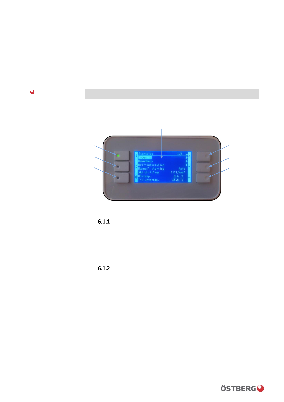
Functions
1
2
3
4
5
6
7
Image no. 1
LCD
See image 1, pos.1
LCD display, blue or white background lighting (adjustable), resolution 240x148.
Display of menus, parameters, parameter values, etc.
Up-▲, Down-▼ and ENTER-√)
See image 1, pos. 2, 3 and 4
Push buttons for navigation in menu.
• Move through the menu with:
- Pos.2 UP-▲
- Pos.3 DOWN-▼
- Pos.4 Select with ENTER- √,
• Change the parameter values:
- Open the value you would like to change by pressing ENTER-√.
- Increase or decrease the value with UP- ▲ / DOWN- ▼
- Acknowledge/confirm the changed value by pressing ENTER- √ again.
• Move to the lower levels by pressing ENTER- √.
If a higher password level is required, you can “take a shortcut” by pressing and
holding down ENTER- √ for about 3 seconds. You will then come directly to password
handling/login/logout. Once you have keyed in the password, you will automatically
return to the previous menu location.
Part no.:
HMI
LCD
Button

26 / 120
Climatix HERU® 400-2400 2018-02-13
Control unit HMI-TM
Info-
See image 1, pos. 5
Button for quick jump to the main index and start page.
• Go to main index
• Switch between main index and start page.
Info LED display
See image 1, pos. 5
The LED display may indicate the following:
• Not lit
- Unit not in operation
• Green/flashing
- Startup
- Night operation test
- Night cooling
- Support operation
• Green/steady light
- Normal operation
• Orange/steady
- Quick stop enabled (designated in the HMI as Emergency stop).
• Orange/flashing
- Fire damper exercise (not available on HERU® CX).
• Alternating Green/Orange
- Operation in Manual mode (see Menu: Start page > Manual
operation).
- Operation in Manual mode (see Menu: Start page > Manual
operation).
▪ Econ. St1
▪ Comf. St1
▪ Econ. St2
▪ Comf. St2
▪ Econ. St3
▪ Comf. St3
To return to time switch program mode, select Auto.
- Room unit overrides settings in HMI
- Manual control of any output or value.
Can mean that one or more of the outputs or values/signals in the HMI are set as
manual values. In this mode, the outputs, parameter values and signals are not
controlled automatically.
When any of the signals or values are set in manual mode, the greatest caution
must be exercised. All use of manual control of signals or values is at your own risk.
When resetting manual control of signals or values, the parameter must always be
reset to ZERO (ZERO stands for automatic mode). All parameters are set to Auto
(Zero) through Main menu > Configuration > Set IO to, select Auto.
Button
LED display
Important!
27 / 120
2018-02-13 Climatix HERU® 400-2400
Control unit HMI-TM
ALARM-
Button
See image 1, pos. 6
Button for Alarm handling.
• Go to alarm list
- If any alarm is active: Alarm list, shows active alarms
- If no alarm is active: Alarm history
• Go in to the latest active alarms in the alarm list
- Possibility to acknowledge/reset active alarm
• Go to alarm entry
- Sorting of alarm list
▪ Name
▪ Time
▪ Prio
▪ Status
- Sorting of alarm history
▪ Name
▪ Time
▪ Prio
▪ Status
Alarm handling is also listed under:
Main index > Alarm handling > Alarm reset:
For more information on alarm handling, see chapter 7.1.1/0.
ALARM -LED display
LED display
See image 1, pos. 6
The LED display may indicate the following:
• LED not illuminated
- No alarm.
• Red/Flashing LED
- One or more alarms are active.
• Red/steady LED
- Tried to acknowledge the alarm, but not reset.
ESC
See image 1, pos. 7
ESC button:
• Takes you back one level in the menu
• Cancels any changes made.
• Go to the main page in HMI: Hold ESC down for about 3 seconds.
(For more info, see chap. 12.1.16)
Button
28 / 120
Climatix HERU® 400-2400 2018-02-13
Control unit HMI-TM
Connecting HMI
If needed, it is possible to extend the cable up to 15 m.
The connector is a modular RJ45, for connection in the
Basic regulator. See image below (PROC1/T-HI).
Tip!
The easiest way to extend the cable is to use a 15 m CAT5 cable and a splice block.
Type: female-female RJ45. (should be X marked)
PROC1 / T-HI
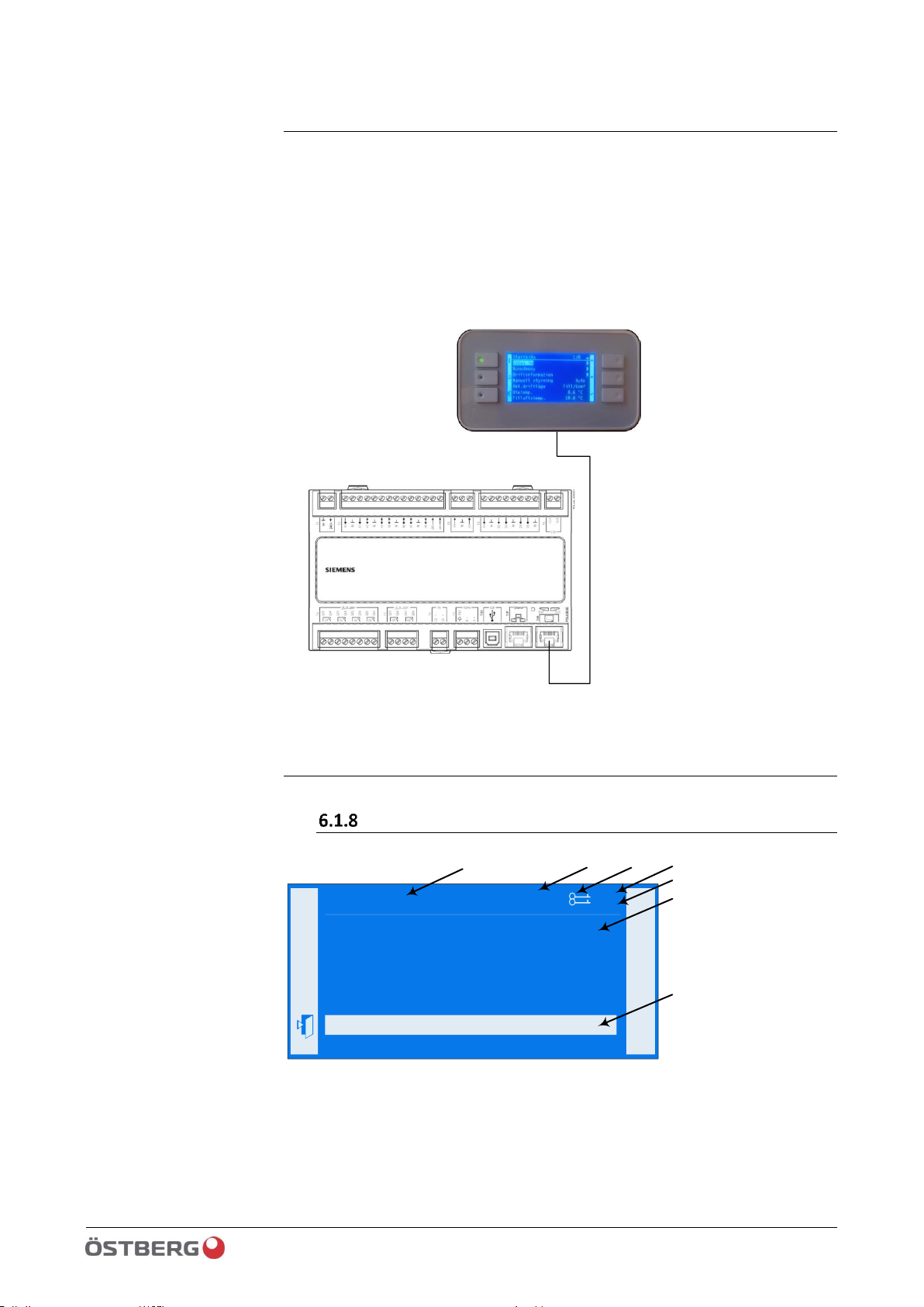
Screen layout
Screen
і
Extract fan off
Actual fan step off
Fire mode off
Fire setpoint 80%
Disable high speed -20.0°C
Disable fan comp None
Summer comp 0.0 %
7/16
Fan control
Disable fan comp None
b
d
a
f
g
c
e
a. Current authority level (For info on authority level, see chap. 3)
• No symbol: No authority level.
• 1st key: authority level 6.
• 2nd key: authority level 4.
• 3rd key: authority level 2.
HMI
Connection
Screen overview

29 / 120
2018-02-13 Climatix HERU® 400-2400
Control unit HMI-TM
b. Title of displayed pages.
c. 7: Number of marked row: 16. Total number of rows on page (incl. this row).
d. The page includes additional rows above; press the up arrow to display.
e. The page includes additional rows below; press the down arrow to display.
f. The navigation arrow shows that there is another level under this level that you
can go to.
g. Marked row.
Navigation rows
off
Extract fan
On the navigation rows, the option selected is shown with dark text on a light-coloured
background when it is marked. In front of the navigation arrow, the current value for
the option is shown.
• Go to the row to be highlighted: Press the up arrow/▲ or down arrow/▼.
• Access the underlying level with the navigation arrow/► : Press Enter √.
Display row
off Operating state
The option selected is shown against a dark background even when viewed in readonly mode. Current value of the option is shown. The navigation arrow is not shown in
read-only mode (non-authorized level).
Preferences row
offNight cooling
The parameter name and the current value are shown against a dark background.
Setting of value:
• Go to the row to be highlighted: Press the up arrow/▲ or down arrow/▼. The
marked row is shown with a dark text against a light background.
offNight cooling
• Switch to preferences page: Press Enter √.
• Set the parameter value: Press the up arrow/▲ or down arrow/▼.
• Close the preferences page and apply the changed parameter value: Press Enter √.
• Close the preferences page without applying the changed parameter value: Press
ESC .
Setting discrete parameter values
6.1.12.1 When only one value is selectable
off
heating
heating cooling
cooling
Navigation row
Display row
Preferences row
Discrete parameter
values

30 / 120
Climatix HERU® 400-2400 2018-02-13
Control unit HMI-TM
The set value is shown on the row preceded by a check mark (here, “Heating”). To
change the value:
• Select the new value: Press the up arrow/▲ or down arrow/▼.
• Switch to editable mode: Press Enter √.
• Set the parameter value: Press the up arrow/▲ or down arrow/▼.
• Close editing mode and apply the changed parameter value: Press Enter √.
• Close the preferences page without applying the changed parameter value: Press
ESC .
6.1.12.2 When several values are selectable
enblLowLimit
√ enblOffNormal
selfRelease
√ typeAlarm
√ evtOffNormal
enblFault
The set value is shown on the row preceded by a check mark. To change the value:
• Select the new value: Press the up arrow/▲ or down arrow/▼.
• Select or deselect the value: Press Enter √.
• Apply the new value(s):
– Go to Done (at the bottom of the menu): Press the up arrow/▲ or down
arrow/▼.
– Select Done: Press Enter √.
or
• Keep the old value and close the preferences page: Press ESC
Setting analog parameter values
0 ↓ 5000
1117
The scale above shows the minimum and maximum values that can be set.
Changing set values:
• Change the value under the arrow: Press the up arrow/▲ or down arrow/▼.
• Increase the value in increments of 10, 100 or 1000. Press and hold down the up
arrow ▲. After a moment, the value will increase by increments of 10, then by
increments of 100, and so on.
• To slow the rate of the increase from 1000s to 100s to 10s to 1s: Do not press the
up arrow ▲ or down arrow ▼for at least a second. The cursor will then move from
1000--->100; after another second, from 100--->10, 10--->1 and so on.
• Keep the new value and close the preferences page: Press Enter √.
or
• Keep the old value and close the preferences page: Press ESC
Selecting one
of several options
Selecting
several options
 Loading...