

OSTBERG HERU S AC, HERU 19 S AC, HERU 14 S AC, HERU 35 S AC, HERU 52 S AC Installation And Directions For Use
Installation and
directions for use
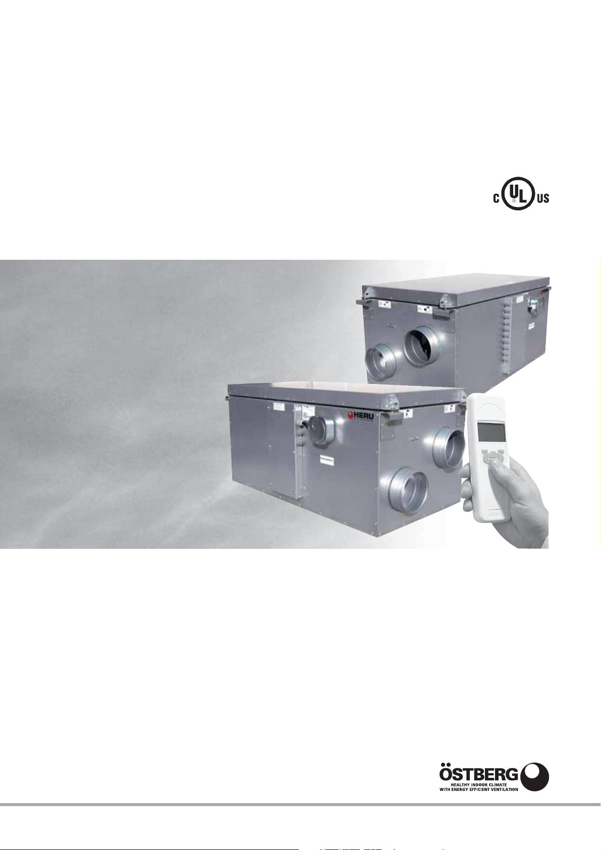
HERU S AC
UL VERSION. Choose language and unit system in the Setting Menu on page 15.

WARRANTY
Warranty period valid according to purchase contract
calculated from date of purchase.
SCOPE OF WARRANTY
This warranty covers faults occurring during the warranty period, which have been notified to the dealer
or verified by Ostberg Americas Inc. (warrantor) or a
representative of the warrantor, and which concern
design, manufacturing or material defects and consequential damages occurring on the product itself.
The above mentioned faults will be rectified so that
the product is made operational.
GENERAL WARRANTY LIMITATIONS
The warrantor’s responsibility is limited in accordance with these warranty terms and the warranty does
not cover property damage or personal injury. Verbal
promises made in addition to this warranty agreement are not binding for the warrantor.
WARRANTY LIMITATIONS
This warranty applies on condition that the product
is used in a normal fashion or under comparable circumstances for its intended purpose and that the
instructions for use are followed.
- Settings; information on use, care, handling, service
or cleaning that are customarily described in the
instructions for use; or works caused by the user
neglecting to observe warning or installation
instructions; or investigation of such are not
covered by the warranty.
- The warrantor is responsible only for the operation
if approved accessories are used.
- The warranty does not cover product failures
caused by accessories/equipment from other
manufacturers.
The unit’s current settings must be noted in the
installation/mounting instructions at installation to
avoid costs in the event of fault. The warrantor is not
liable for costs such as adjustment costs related to
the replacement of fans and control boards in the
unit.
SERVICE TERMS DURING
THE WARRANTY PERIOD
According to your agreement with your local distributor.
This warranty does not cover faults caused by:
- Transport of the product.
- Careless use or overstraining of the product.
- Failure on the part of the user to follow instructions concerning installation, use, maintenance,
care and handling.
- Incorrect installation or incorrect positioning of
the product.
- Conditions that are not due to the warrantor, e.g.
excessive voltage variations, lightning, fire and
other accidents.
- Repair, maintenance or design changes made by
an unauthorized party.
- Faults that do not impact operation, e.g. surface
scratches.
- Parts that through handling or normal wear are
exposed to greater than average hazard, e.g. lamps,
glass, ceramic, paper and plastic parts, and filters
and fuses are not covered by the warranty.
RECTIFICATION MEASURES
WHEN A FAULT IS DETECTED
When a fault is detected, the customer must notify
this to the dealer. Specify what product this applies
to (part number and manufacture date – year and
week – are listed on the product label), and describe
the fault and how it occurred as accurately as possible. For a warranty repair to be performed, the customer must prove that the warranty is valid by presenting the receipt of purchase. After the warranty
period has expired, warranty claims that have not
been made in writing before the expiration of the
warranty period will not be valid.
In all other respects according to our conditions
of sale.
NOTE!
Ostberg Americas Inc. reserve the right to make
changes without further notice.

CONTENTS
WARRANTY . . . . . . . . . . . . . . . . . . . . . . . . . . . . .2
UNIT DESCRIPTION . . . . . . . . . . . . . . . . . . . . . . . .4
INSTALLATION AND SECURITY . . . . . . . . . . . . . .5
”USE” ”SECURITY” ”MOUNTING” . . . . . . . . . . . . . . . . .5
”PLACING” ”FREE SPACE” . . . . . . . . . . . . . . . . . . . . . . .6
”ASSEMBLY INSTRUCTIONS” . . . . . . . . . . . . . . . . . . . . . .6
”SCHEMATIC DIAGRAMS FOR PLACING” . . . . . . . . . . . .6
STARTING UP THE UNIT . . . . . . . . . . . . . . . . . . . .7
CONTROL DIAGRAM . . . . . . . . . . . . . . . . . . . . . .8
REGULATION FUNCTIONS . . . . . . . . . . . . . . . . . .9
OPERATING THE CONTROL UNIT . . . . . . . . . . .10
VIEW MODES 1-3 . . . . . . . . . . . . . . . . . . . . . . . .11
MAIN MENU . . . . . . . . . . . . . . . . . . . . . . . . . . . .12
”FAN SPEED” MENU . . . . . . . . . . . . . . . . . . . . . .12
”TEMPERATURE” MENU . . . . . . . . . . . . . . . . . . .12
”BOOST” MENU . . . . . . . . . . . . . . . . . . . . . . . . .12
”OVERPRESSURE” MENU . . . . . . . . . . . . . . . . . .13
”WEEK TIMER” MENU . . . . . . . . . . . . . . . . . . . .13
”POWER ON/OFF” MENU . . . . . . . . . . . . . . . . .14
”ALARMS” MENU . . . . . . . . . . . . . . . . . . . . . . . .14
”SETTINGS” MENU . . . . . . . . . . . . . . . . . . . . . . .15
THE ”SERVICE MENU” . . . . . . . . . . . . . . . . . .15-23
”PRESSURE INPUTS” ”FILTER MEASUREMENT”
”AC FAN SETUP” . . . . . . . . . . . . . . . . . . . . . . . . . . . . . .16
”DISPLAY CONTRAST” ”BOOST”
”OVERPRESSURE” ”MAX TEMPERATURE” . . . . . . . . . . .17
”ALARM” . . . . . . . . . . . . . . . . . . . . . . . . . . . . . . . . . . .18
”CO2” ”RH” ”HEATER” . . . . . . . . . . . . . . . . . . . . . . . .19
”COOLER” ”SUPPLY LIMITS”
”REGULATION MODE” ”MODBUS” . . . . . . . . . . . . . . . .20
”SUMMER COOLING” ”FREEZE PROTECTION”
”FLOW DIRECTION” . . . . . . . . . . . . . . . . . . . . . . . . . . .21
”SENSOR CALIBRATION” ”LOAD/SAVE SETTINGS”
”VERSION INFO” . . . . . . . . . . . . . . . . . . . . . . . . . . . . . . .22
”DEVICE PAIRS” . . . . . . . . . . . . . . . . . . . . . . . . . . . . . . . .23
CHANGING FROM EC TO AC MODE . . . . . . . . .23
OTHER FUNCTIONS . . . . . . . . . . . . . . . . . . . . . .23
SERVICE . . . . . . . . . . . . . . . . . . . . . . . . . . . . .24-25
ACCESSORIES . . . . . . . . . . . . . . . . . . . . . . . . . . .26
SPARE PARTS . . . . . . . . . . . . . . . . . . . . . . . . . . .27
ERROR DETECTION DIAGRAM . . . . . . . . . . .28-29
ERROR DETECTION . . . . . . . . . . . . . . . . . . . . . . .30
INTERNAL SETTINGS . . . . . . . . . . . . . . . . . . . . .31
TECHNICAL INFORMATION
DIMENSIONS . . . . . . . . . . . . . . . . . . . . . . . . . . .34
FLOW DIRECTION . . . . . . . . . . . . . . . . . . . . . . . .35
TECHNICAL DATA . . . . . . . . . . . . . . . . . . . . . . . .35
SOUND DATA . . . . . . . . . . . . . . . . . . . . . . . .36-37
PRESSURE/FLOW DIAGRAMS . . . . . . . . . . . .38-39
WIRING DIAGRAMS . . . . . . . . . . . . . . . . . . .40-41
This ”Installation and directions for use” contains following products:
HERU 14 S AC, HERU 19 S AC, HERU 35 S AC and HERU 52 S AC.
IMPORTANT! Please read this manual before installing the unit.
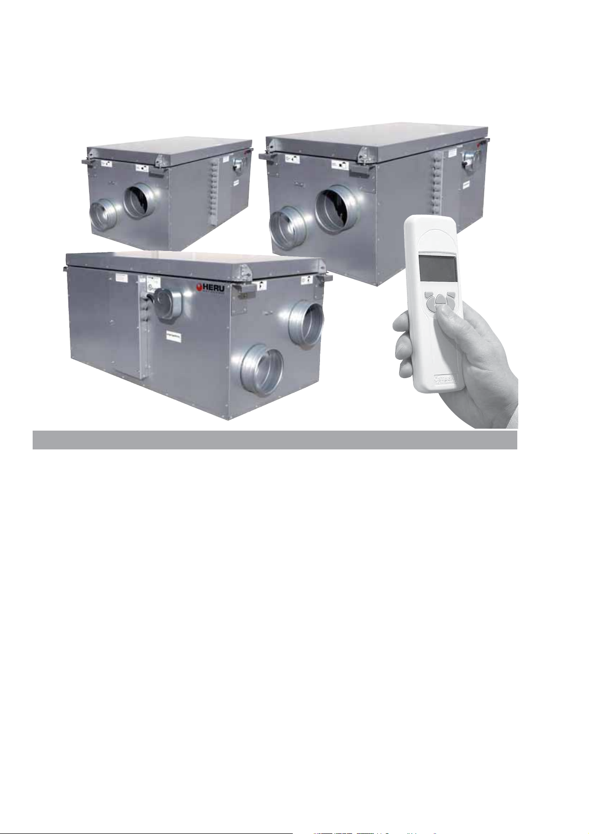
HERU 14 S AC
HERU 19 S AC
HERU 52 S AC
UNIT DESCRIPTION
• HERU S is approved according to the standard
UL 1812 ”Ducted Heat Recovery Ventilators” and
CSA-C22.2 No. 113 ”Fans and Ventilators”.
• HERU S is a heat recovery unit (HRV) or an energy recovery unit (ERV). It is designed for supply
and exhaust air ventilation combined with heat
and cool recovery.
• HERU S can be used in both residential and commercial applications such as homes, apartments,
offices and schools etc. where there is a need for:
-clean. filtered and fresh air
-high temperature efficiency
-energy saving
-safe and quiet operation
• HERU S;
- has a rotating heat exchanger, of hygroscopic or
non-hygroscopic type and is manufactured of aluminium, placed centrally in the unit. The ERV exchanger has a humidity efficiency of up to 85%.
The HRV exchanger has a temperature efficiency
of up to 85%.
- has backward curved centrifugal fans with maintenance free external rotor motors, which are connected with quick contacts, and are easy to
remove for cleaning.
HERU 35 S AC
- has built-in control for heating/cooling.
- can be fitted with a built-in electric heater.
- has as standard, disposable bag filters,
class MERV 13.
- has a wireless remote controller for the operation
and monitoring of the unit.
- has as standard, Modbus communication via
RS485.
- has a double skinned galvanised sheet steel casing
with intermediate insulation.
• The HERU S can be mounted in either warm or
cold space.
• The HERU S is delivered galvanized.
• All HERU S are operated via a wireless remote
controller which can operate and to preset the required parameters as well as monitor the unit’s
status. The operating range is approximately 50
meters/164 feet.
The antenna which is placed next to the unit can
have the range reduced if there are heavy reinforcing bars in the concrete structure and it should
then be moved either to a position where the signal is not shielded or nearer to the controller.
4

INSTALLATION AND SECURITY
USE
• To achieve as comfortable indoor climate as possible and to avoid moisture damage to the property, the house needs a continuous and adequate ventilation. The unit must run continuously and only
be stopped for maintenance.
The air flow is controlled by settings in the wireless control unit:
Away – Reduced airflow, can be used when no one
is at home.
Normal – This is adjusted by the installer and
should not be changed by the user.
Boost – A higher air flow than normal, selectable
medium/max. Should be used when there is a need
for a higher air flow than the default mode is
adjusted for, such when cooking, drying laundry,
shower and sauna.
Recommendations for drying laundry: Because of
the high moisture content, an exhaust air tumbler
or a drying cabinet should not be connected to the
system. We recommend a condensing tumbler
without duct connection.
• When installing HERU consideration must be
given to any approval authority requirements and
recommendations concerning siting, accessibility,
electrical connections, etc.
• The HERU unit is accessible for the user, according to IEC 60335-2-40, to by themselves do the
service and maintenance, according to this
Directions for use. But before this work the unit
must be currentless.
With reservation according to IEC 60335-2-7.12
”This appliance is not intended for use by persons
(including children) with reduced physical, sensory or metal capabilities, or lack of experience and
knowledge, unless they have been given supervision or instruction concerning use of the appliance
by a person responsible for their safety.”
”Children should be supervised to ensure that they
do not play with the appliance.”
• The HERU unit should be storage in a sheltered
and dry place before installation.
• Dimensioned air flow should not exceed 60% of
the unit's maximum capacity.
• Check at regular intervals that supply air and exhaust air works.
• To avoid condensation in the unit during the cold
season, the unit should not be turned off for a
longer period. When installed in warm moisturre
environment as e.g. bathroom and utilityroom condense may appear on the outside of the unit at low
outside temperatures.
currentless. If there is a need of changing or complement any electrical components, it should be
done by a qualified person.
• The HERU unit includes rotating parts that could
cause serious danger on the occasion of contact.
This is why the unit must be duct connected and
the lid closed with the screws tightened, before
starting up the unit.
• After the current is cut for service and maintenance the electric heater may still be warm.
• Make sure that the access cable is not damage
when mounting and installation.
• HERU must be equipped with residual-current
device (RCD).
• The HERU S needs a permanent electrical supply.
• The unit must be connected via a safety switch.
Any electrical connections must be made by a qualified electrician.
• Keep in mind that rotating, warm and electrical
components can cause serious damage.
MOUNTING THE HERU S
• HERU S should be installed according to the
assembly instructions. See picture on next page.
• Place the unit on a insulation board, min. 2 inch.
• Supply and exhaust air must be duct connected on
the same side of the unit.
• Acoustic silencer should be planned with the help
of sound data and required sound levels.
• Use duct clamp or flange with encompassing insulation when connecting to duct.
• If the supply and the exhaust air ducts are installed
in a cold space they should be insulated. To prevent condensation the supply air duct should also
be insulated if installed in warm space at low supply air temperatures.
• The fresh air and extract air duct should always be
condense insulated.
• The ducts should be insulated all the way towards
the unit.
• The duct sensor GT7 should be mounted in the
supply air duct, and the antenna on a suitably position beside the unit (not against metal).
• If a heating coil is connected a cut off damper must
be mounted in the fresh air duct.
• Cooker hoods must not be connected to the
HERU S because of the increased cleaning demand.
• Ducting must be conntected to external ground on
the unit, see picture.
SECURITY
Caution! Do not apply electric power until after
completion of the installation. Ensure the installation
and wiring is in accordance with CEC, NEC and
local electrical codes..
• Attention, look out for sharp edges and corners on
the HERU unit and fans.
• Consider the weight of the unit. See page 35.
• Before maintenance work the HERU unit must be
External
ground.
5
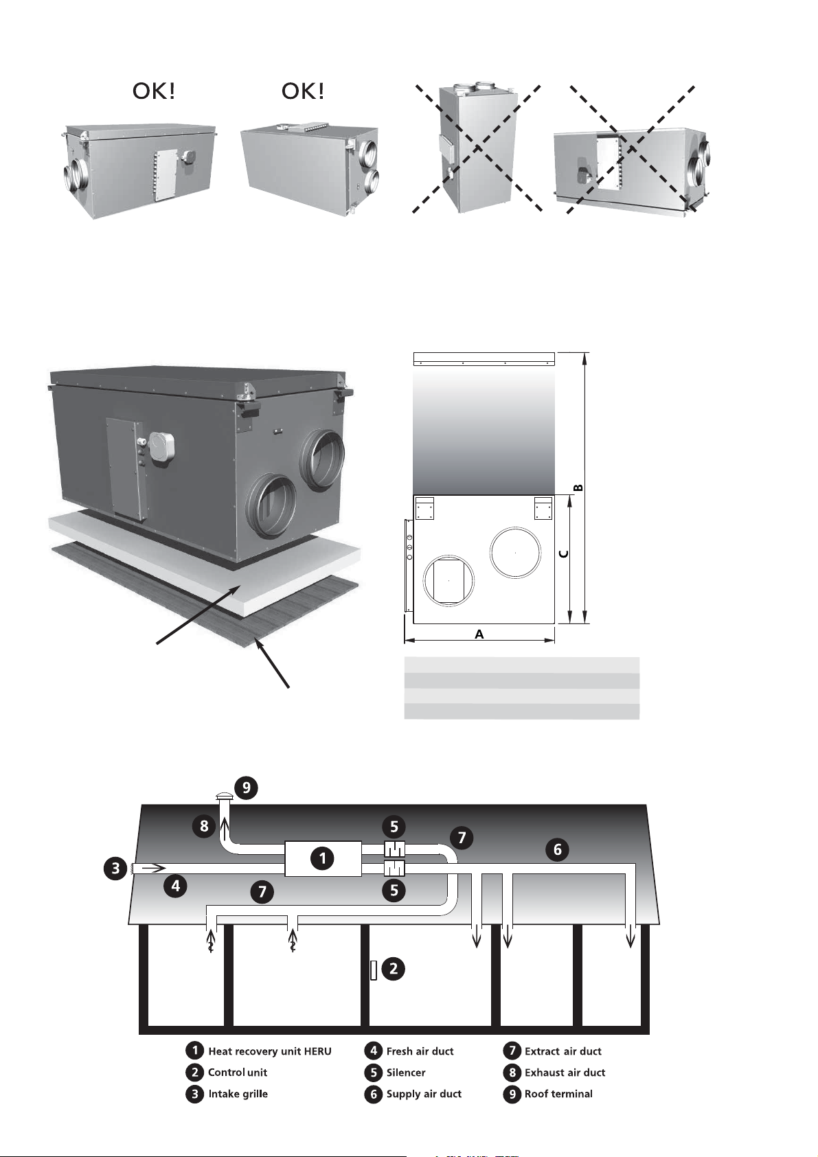
PLACING THE HERU S UNIT
A B C D
The HERU S should be installed with the lid upwards (A) or on the side (B). Because of the risk of injury
we do not recommend installing the unit vertically (C) or with the lid downwards (D). Allowances must be
made to access the unit for servicing or maintenance.
ASSEMBLY INSTRUCTION
INSULATION BOARD
min. 2 inch
FLOOR
CLEARANCEE FOR SERVICING
AND MAINTENANCE
Clearance for servicing
and maintenance
Inch A+D B C
H E R U 14 S/19 S 21
H E R U 35 S 24 39
H E R U 52 S 28 48 24
7/8
1/2
31
16
3/8
1/2
20
7/8
SCHEMATIC DIAGRAM FOR HERU S PLACED IN AN ATTIC
6

STARTING UP THE UNIT
NB! Important information before starting!
WARNING!
Improper installation, adjustment, alternation, service or maintenance can cause property damage, per-
sonel injury or loss of life.
Installation and service must be performed by a
qualified installer or service agency.
Carefully read through the manual before starting
up the unit.
• NB! Always mount the temperature sensor GT7 in
the supply air duct. See page 8. GT7 is connected at the relay card.
• The antenna should be mounted outside the unit.
The antenna for HERUS is connected ans is located in the connection box when delivered.
NB! The antenna should not
any metal area or metal items as this will shield
the signal.
The antenna should be mounted as central as
possible. This to achieve the best signal all over
the house. If needed an extension cord is available
as an accessorie.
• Install the 3 AA batteries in the wireless control
unit that are placed inside the HERU
vered.
• HERU starts automatically (with a few minutes delay) when the power is switched on, or
alternative with the wireless control unit. At power
outage, always check so the unit is starting up
again.
be mounted against
®
when deli-
• HERU S is supplied for right handed application,
see picture below. If the unit is installed left
handed, and no electrical heater is fitted, changes
can be made in the ”Service Menu” and in the submenu ”Flow Direction”. See page 20.
• Important when adjusting the flow: Go to Service
Menu (password 1199), choose “AC -motor setup”.
This disable functions such as Summer cooling or
Boost during flow adjustment. The fan speed is
standard. See page 21.
When adjusting the airflow of AC-fans there is a
possibility to change the voltage for the different
fan speeds via the separate transformers for supply
resp. exhaust fan. Normal operation should be
done in standard mode. Wiring diagrams with trans-
former steps see pages 40-41.
All HERU S has 7-step transformers. See wiring
diagrams on pages 40-41.
Note! When ajusting fan speed manully, make
sure that the speed keeps the sequences.
• All HERU can be fitted with a built-in electric
heater. Choose heater ”On/Off” according to the
instruction on page 19. For a heating coil see
instruction on page 19.
• Set the temperature according to the instruction
on page 12.
• Save settings according to the instruction on page
22.
• Note! The unit must not be operating without
filter.
EXHAUST
AIR
FRESH
AIR
EXTRACT
AIR
SUPPLY
AIR
CONTROL CABINET
7
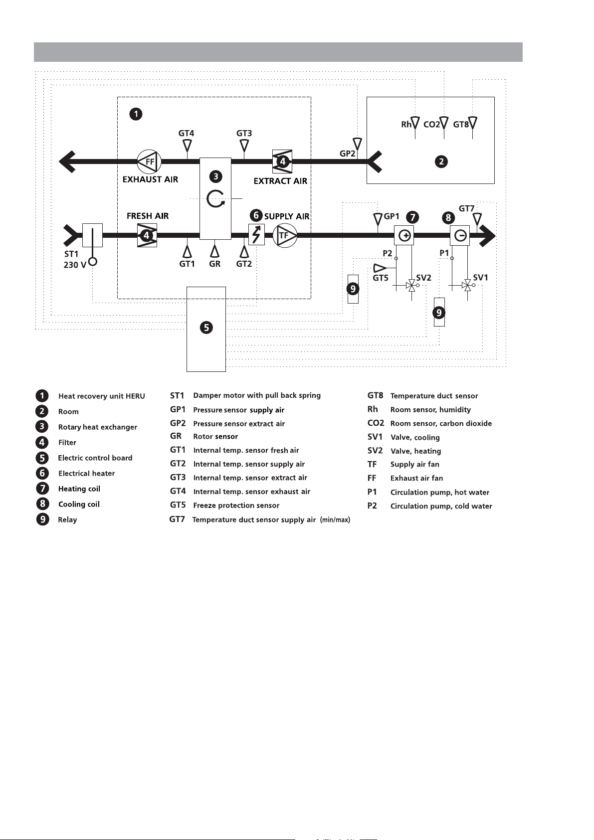
CONTROL DIAGRAM HERU S
shows all sensors, flow direction right
*Accessories
*
*
*
*
*
*
*
*
*
*
*
*
*
8

REGULATION FUNCTIONS
REGULATE THE TEMPERATURE
The air temperature can be regulated either for constant supply air temperature, constant room temperature or constant exhtract air temperature.
For constant room temperature a sensor should be
placed in the room for room regulation (this is also
suitable when a cooling coil is incorporated in the
system).
Extract air regulation functions in a similar way
but with the difference being that the sensor is
placed at the extract air of the unit.
The temperature can be regulated in 5 sequences:
1.Cooling recovery + After cooling: The regulation
unit can regulate a cooling coil (e.g. cooling water
from bedrock), when the cooling recovery from
the rotor is not enough.
2.Cooling recovery or regulated after cooling: The
rotary heat exchanger starts if the extract air tem-
perature is lower than outside temperatur.
Regulated after cooling: The aftercooling starts
when the outside temperature is lower than de-
sired room temperature and is not enough to lower
the room temperature.
3.Outside temperature = desired temperature: When
the outside temperature is the same as desired sup-
ply air temperature the rotor stops.
4.Heat recovery: The rotary heat exchanger starts to
recover the warmer room temperature.
5.Heat recovery + heat: In climate conditions where
the rotary heat exchanger, in spite of its high effi-
ciency, is not sufficient to reach the desired supply
air temperature, the controller can regulate either
the built-in electric duct heater or a heating coil.
FAN CAPACITY
Airflow (fan speed) is regulated via the week timer
that can be programmed for specific time points
when the fan speed should change from one speed to
antoher (e.g. home or away setting). A special feature
is that you can pressure compensate when supplementary heating, using an open fire or stove (the
extract air fan then drops to a lower speed).
With the weektimer function it is possible to
schedule different fan speeds e.g away/boost or
standby. The fan speed can also be controlled by a
carbon dioxide (CO
that the unit gives a higher airflow (boost) when the
maximum limit value has been exceeded.
”Summer Cooling” is a function where you can use
the cool outside temperature to cool down the inside
air. The fan speed is boosted when the ratio between
the outside temperature and the extract air temperature is within the programmed criteria.
Via the wireless control unit the HERU can be put in
an ”Off mode”, which means that the motors for fans
and rotor are ”Off” but the unit is ”Stand by”. If there
is a requirement of totally cut off power, a disconnect switch must be mounted on the main electrical
feed.
Boosting the airflow for a specified time can be done
via the wireless control, there is also a opportunity to
do that via a timer connected to the ”0” and ”Boost”
connection on the PCB. With the connectors closed
the boost function will be ”On”.
) and humidity (RH) sensor so
2
Regulated
after cooling
0-100%
Rotor 100%
1.
Cooling recovery
+
After cooling
Regulated rotor
0-100%
2.
Cooling recovery
Regulated rotor
0-100%
4.
Heat recovery
or After cooling
3.
Outside temperature = Desired temperature
9
Regulated
after heating
0-100%
Rotor 100%
5.
Heat recovery
+
After heat
OPERATING THE CONTROL UNIT
StdStd
SYSTEMSYSTEM OK
......
50°F
54°F
70°F
72°F
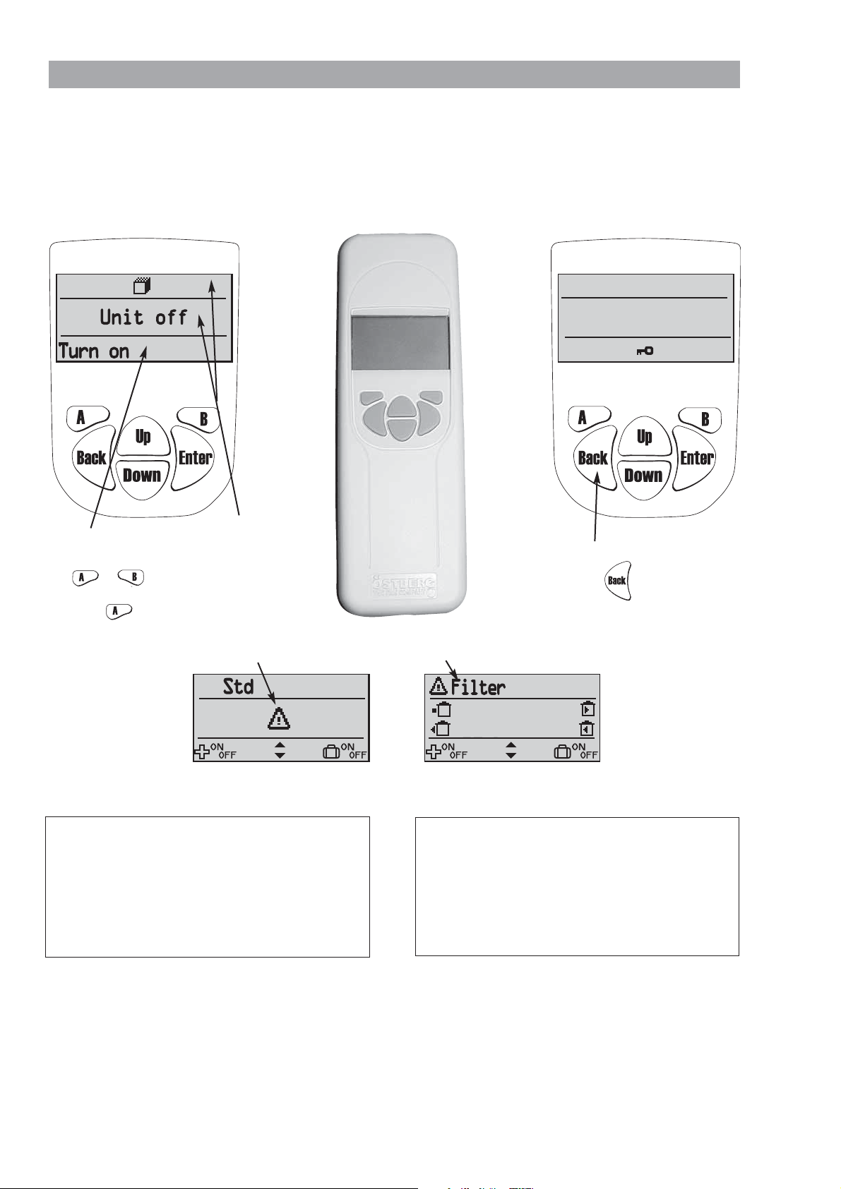
Information of the units current status such as temperature, fan speed, the rotor temperature efficiency when
operating, heat respectively cooling needs is shown in the VIEW MODE 1, 2, 3 and 4. These menus is normally
not lit up for battery-saving purposes but is lit up after the first press of the button and is switched off after
about 2 minutes of not being in use.
The control unit automatically returns to VIEW MODE 1 after one minute when one has viewed other submenus.
NB! At new setting a delay of 15 seconds should be taken into consideration.
Top row and
Bottom row shows the
possible choices with
key or .
E.g turn on/off the unit
middle field
displays current
values and
activities.
with the key.
VIEW MODE 1 shows alarm and VIEW MODE 2 shows what kind of alarm.
USER INFORMATION FOR RF DEVICE:
FCC ID: A8W-4020528
This device complies with part 15 of the FCC Rules
and RSS-210 of IC Rules. Operation is subject to
the following two conditions: (1) This device may
not cause harmful interference, and (2) this device
must accept any interference received, including
interference that may cause undesired operation of
the device.
Changes or modifications not expressly approved by the
party responsible for compliance could void the user’s authority to operate the equipment.
This exuipment has been tested and found to comply
with the limits for Class B digital device, pursuant to part
15 of the FCC Rules. These limits are digned to provide
reasonable protection against harmful interference in a
residential installation. This equipment generates, uses and
can radiate radio frequency energy and, if not installed and
used in accordance with the instruction, may cause harmful interference to radio communications. However, there
To activate or disable the keylock;
press down the key for 3 seconds.
This device complies with part 15 of the FCC Rules
and RSS-210 of IC Rules. Operation is subject to
the following two conditions: (1) This device may
not cause harmful interference, and (2) this device
must accept any interference received, including
interference that may cause undesired operation of
the device.
is no guarantee that interference will not occur in a particular installation. If this equipment does cause harmful
interference to radio or television reception, which can be
determined by turning the equipment off and on, the user
is encouraged to try to correct the interference by one or
more of the following measures: -Reorient or relocate the
receiving antenna. -Increase the separation between the
equipment and receiver. -Connect the equipment into an
outlet on a circuit different from that to which the receiver is connected. Consult the dealer or an experienced
radio/tv technician for help.
FCC ID: ASW-4020527
10
CO2
+
CO2
+
5
50°F
54°F
70°F
72°F
50°F
54°F
70°F
72°F
72°F
68°F
68°F
...
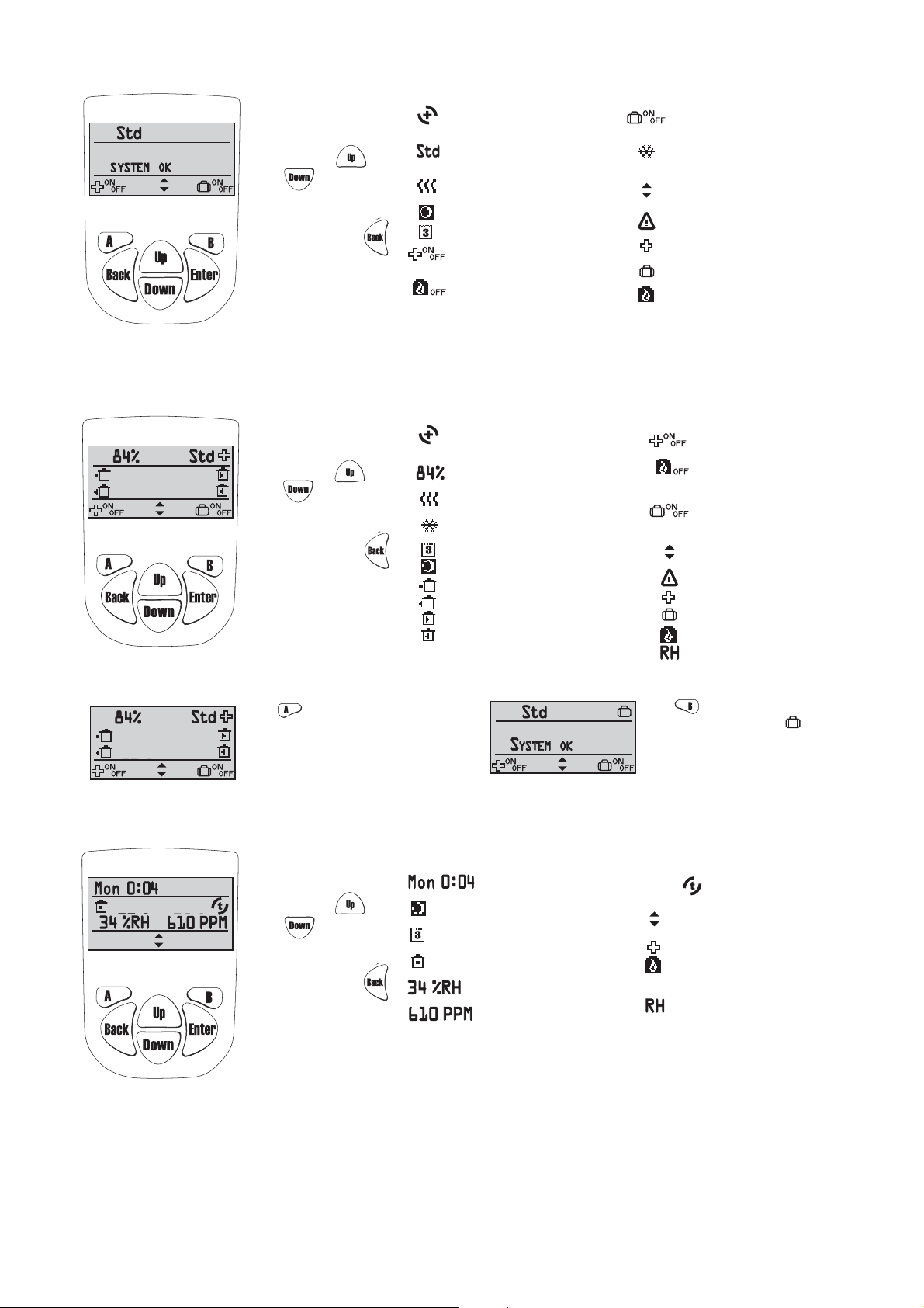
In order to go
view mode 2, 3
or 4 press
or .
In order to
return to view
mode 1, press .
In order to go
view mode 3
or 4 press
or .
In order to
return to view
mode 1, press .
VIEW MODE 1
SYMBOLS THAT CAN BE DISPLAYED IN VIEW MODE 1:
= Indicates that the rotor is operating.
++= heat recovery
- = cooling recovery
= Fan speed. Choose from min,
standard, medium, max.
= Symbol indicates that
the heating coil is on.
= Summer cooling is active.
= Week timer is active.
= Function of A-key.
Press A-key to regulate ”boost”
of supply & exhaust air flow.
= Function of B-key.
Press B-key to turn off
pressure compensation.
VIEW MODE 2
SYMBOLS THAT CAN BE DISPLAYED IN VIEW MODE 2:
= Indicates that the rotor is operating.
= heat recovery
- = cooling recovery
= Temperature efficiency.
= Symbol indicates that
the heating coil is on.
= Symbol indicates that
the cooling coil is on.
= Week timer is active.
= Summer cooling is active.
= Outside temperature.
= Exhaust air temperature.
= Supply air temperature.
= Extract air temperature.
= CO
C
compensation is active.
2
= Function of B-key.
Press B-key to choose
”Away” on or off.
= Symbol indicates that
the cooling coil is on.
= Function of keys up and down
for view mode 2, 3 and 4.
= Alarm
= Indicates Boost is active.
= Indicates Away is active.
= Pressure compensation is active.
= Function of A-key.
Press A-key to regulate ”boost”
of supply & exhaust air flow
= Function of B-key.
Press B-key to turn off
pressure compensation.
= Function of B-key.
Press B-key to choose
”Away” on or off.
= Function of keys up and down
for view mode 1, 3 and 4.
= Alarm
= Indicates Boost is active.
= Indicates Away is active.
= Pressure compensation is active.
= RH compensation is active.
IN VIEW MODE 1 AND 2 BOOST OFF/ON AND AWAY OFF/ON CAN BE CHOOSEN.
Press key to choose
supply & exhaust air flow for a specific time
(time and fan speed settings during the boost
is made in the Service menu ”Boost” page 69).
When the ”plus”
right corner, the boost is activated.
Boost off/on
+
symbol is displayed in the
of the
VIEW MODE 3
In order to go
view mode 2
or 4 press
or .
In order to
return to view
mode 1, press .
SYMBOLS THAT CAN BE DISPLAYED IN VIEW MODE 3:
= Display weekday and time.
= Indicates that Summer
cooling is active.
= Indicates that week timer
is active.
= Room temperature.
Sensor placed in room.
= Relative air humidity in per cent.
= Carbon dioxide level in PPM
(part per million).
Press key to choose
When the symbol ”suitcase” is
displayed in the right corner, the away
mode is activated, i.e. the fan speed is
minimum.
= Supply air temperature
after the rotor.
= Function of keys up and down
for view mode 1, 2 and 4.
= Indicates Boost is active.
= Pressure compensation is active.
compensation is active.
= CO
2
= RH compensation is active..
Away off/on
.
11
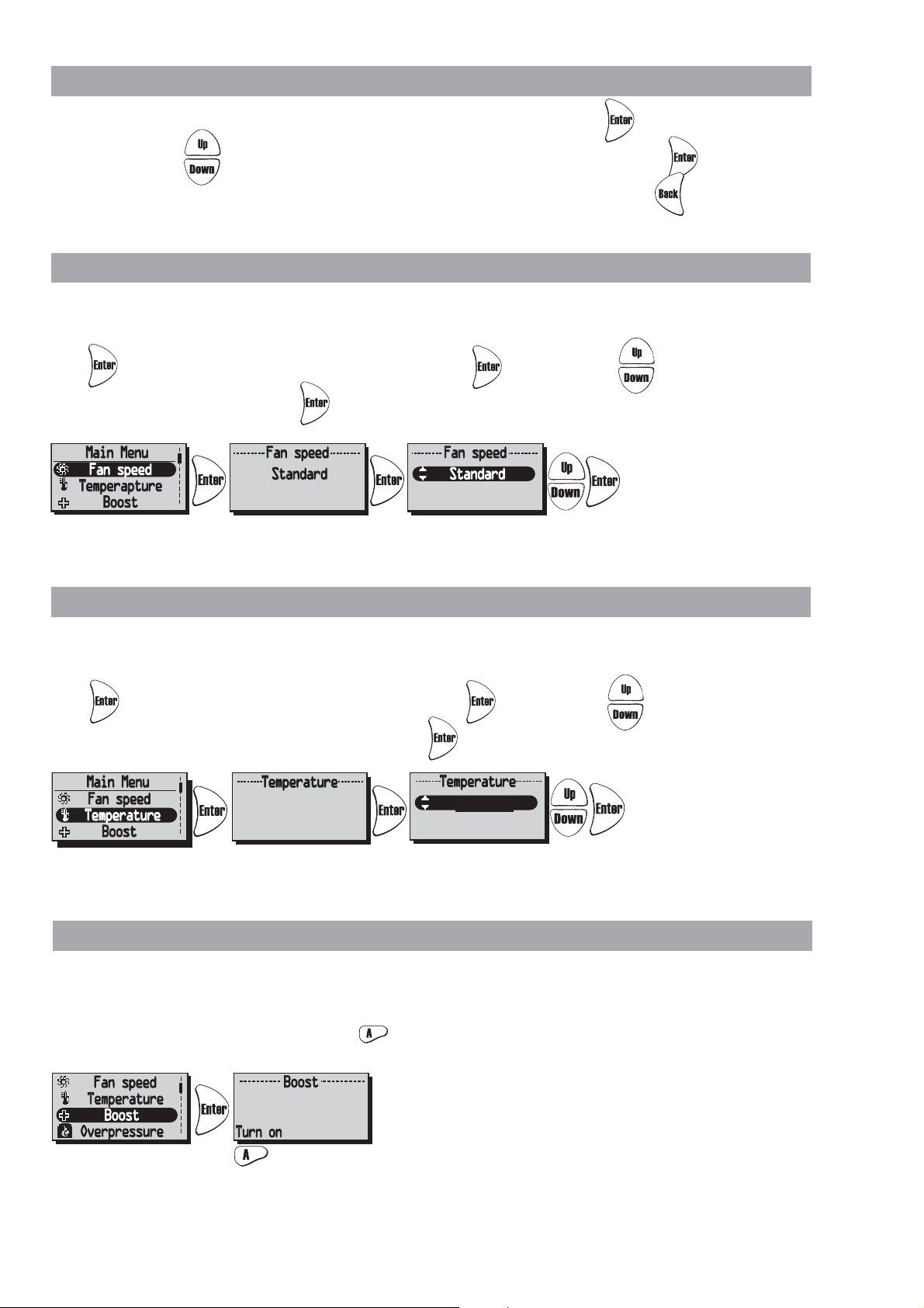
”MAIN MENU”
Off
70°F
70°F
In order to go forward in the menu from the View mode to the Main Menu press .
In the Main Menu is used to select the desired menu, after the choice is made with .
The procedure is the same in the submenu. In order to return to the previous page press .
”FAN SPEED” MENU (Only for HERU
In this menu desired fan speed is chosen. You can choose from 4 speeds: Min, Standard, Medium and Max.
Normal operation should be done in standard mode
Press in order to go forward from the Main Menu. Press again and then in order to choose
the desired fan speed. Confirm with .
Made settings is overridden if Week Timer is activated.
®
AC)
”TEMPERATURE” MENU
In this menu desired temperature is chosen (supply air, extract air or room temperature) depending on what
kind of regulation that is choosed, see page 20.
Press in order to go forward from the Main Menu. Press again and then in order to choose the
desired temperature (15-30°C/59-86°F). Confirm with .
Made settings is overridden if Week Timer is activated.
”BOOST” MENU
In this menu Boost On/Off is chosen. The time has the factory setting of 30 min. and fan speed Medium.
To adjust the fan speed and time, see page 17.
Boost is activated/disable (On/Off) with the key.
O
The Boost function can also be activated with an external switch with double pressure or timer.
See wiring diagram page 40-41. The Boost is On as long as the breaker is closed.
12
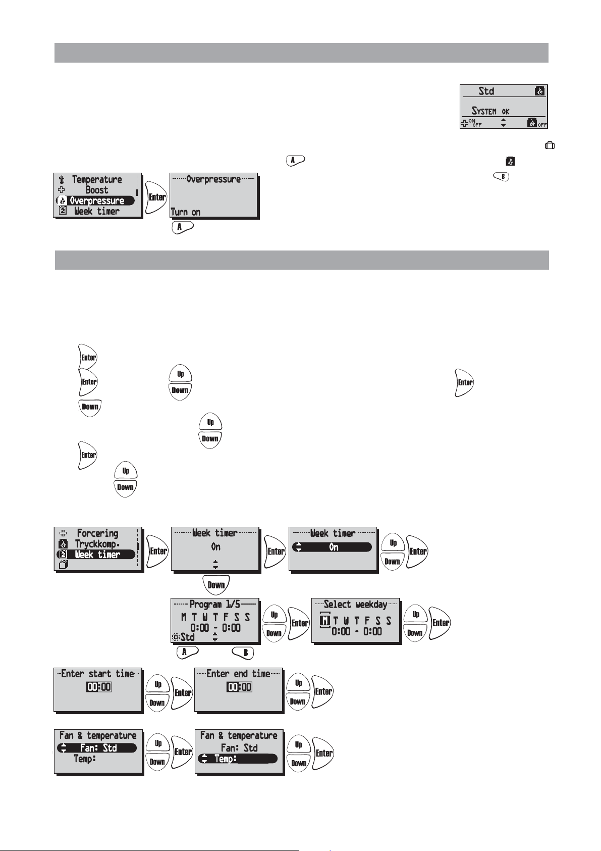
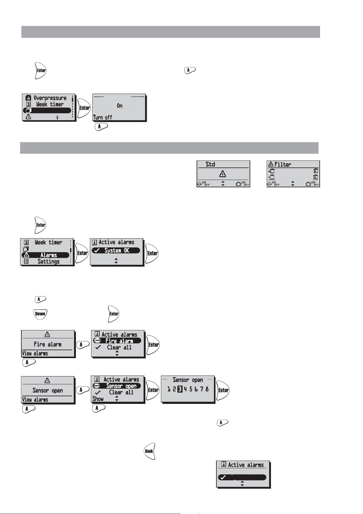
“OVERPRESSURE” MENU
Off
Power On/Off
70°F
70°F
70°F
Overpressure is a special feature were you can pressure compensate when supplementary
heating using an open fire or stove. The exhaust air fan then drops to a lower speed
during set time.
In this menu Overpressure On/Off is chosen. The time has the factory setting of 15 min.
To adjust the time, see page 17.
Overpressure is activated/disable (On/Off) with the key.
O
When pressure compensate is
activated the symbol ”Away”
will be change to the symbol
”Overpressure” in View
mode 1 and 2.
Than press directly in the
View mode to turn off Overpressure.
“WEEK TIMER” MENU
When in normal operation the unit runs with the fan speed that was choosen in the “Fan Speed” menu and
the temperature that was choosen in the “Temperature” menu. A departure from these programmed values that
you periodically want to recall is done in this menu. For example if you want to have a lower flow/temperature
during the daytime when nobody is at home then there is the possibility to adjust this here.
Week timer. If end time is the same or less than start time the program will end the following day.
Press in order to go forward from the Main Menu.
Press again and then in order to choose off/on of the week timer. Confirm with .
Press to choose/adjust the desired program. There are 5 programs for the adjustment of the fan speed
and temperature available. Press to choose a program.
Press in order to go forward to choose a weekday, start time, end time, fan speed and temperature.
Use the keys to choose the settings of weekday, start time, and end time, fan speed (Min, Standard,
Medium, Max, Standby*) and temperature (15-30°C/59-86°F).
Cont. next line.
Cont.
Cont. next line.
Cont
* Standby mode must only be used if a motorized damper is mounted on the exhaust and fresh air duct, in order to
protect from condensation inside the unit. The dampers should be connected to the control board "Duct valve".
N.B! The activated Week Timer over-
rides the manuel settings of fan speed
and temperature.
Program with the lowest index has
priority when two programs overlap
each other. E.g. Program 1 has priority
over program 2 when overlapped.
13
“POWER ON/OFF” MENU
! Filtertimer
Reset
Power On/Off
Settings
Power On/Off
Power On/Off
50°F
54°F
70°F
72°F
In the ”Power On/Off” Menu you have the possibility of turning off the unit via the wireless control unit.
NB! The unit must be currentless during service and maintenance.
Press in order to go forward from the Main Menu. Press in order to choose on/off of the unit.
When "On" is displayed in the center of the display, the unit is on. When "Off" is displayed the unit is off.
To avoid condensation in the unit during the cold season
the unit should not be turned off for a longer period.
“ALARMS” MENU (Displayed only if an alarm is triggered)
This meny displayes triggered alarms.
View mode 1 shows alarm and
View mode 2 shows what kind of alarm.
Alarms is shown for:
• ”Fire alarm” • ”Sensor open” • ”Sensor shorted” • ”Overheating”• ”Freeze alarm” • ”Supply temp. low”
• ”Rotor temp. low” • ”Rotor failure” • ”Filter” • ”Filter timer” • ”Supply fan alarm” • ”Exhaust fan alarm”
Press in order to go forward from the Main Menu and to view status.
When alerting a dialogue box for the alarm is shown in the Main Menu and the display will flash.
“View alarms” is shown and the possibility for equalization is given.
Press to see the cause of alarm in Submenu. Control the cause and remedy the alarm.
Press to ”Clear all” and than .
Current alarm is viewed. When "Sensor open" and "Sensor shorted" press "Show"
to view which sensor GT 1-8 is alerting.
See Control diagram on page 8.
In order to return to the previous pages press .
When alarm for Filter timer is triggered it can be equalized with Reset.
A reminder to change filter comes in a seven-day interval.
To restart the timer see ”Service Menu Alarm” page 18.
14
!
 Loading...