

Page 1

...................................................................................................................
Application Note
iConverter®
Managed Fiber Media Converter
Product Family
iConverter XG, XG+ and XGT+
Chassis Installation Guidelines for Airow and Cooling
Document Number: 002-A0006
Version E
June 2018
Omnitron Systems Technology, Inc.
38 Tesla
Irvine, CA 92618
tel: (949) 250-6510
www.omnitron-systems.com
Page 2

Application Note
Doc. No. 002-A0006
Rev E
Table of Contents
1.0 SCOPE ..........................................................................................................................................................3
2.0 XG PLUG-IN MODULE REQUIREMENTS ........................................................................................... 3
3.0 XG+ AND XGT+ PLUG-IN MODULES REQUIREMENTS .................................................................5
3.1 Installation Guidelines When Using the 19-Module Chassis .........................................................5
3.2 Installation Guidelines When Using the 5-Module Chassis ...........................................................8
3.3 Installation Guidelines When Using the 2-Module Chassis ...........................................................9
3.4 INSTALLATION GUIDELINES WHEN USING THE 1-MODULE CHASSIS ................................ 10
©2018 Omnitron Systems Technology, Inc. – All rights reserved.
Page 2
Page 3
Application Note
Doc. No. 002-A0006
Rev E
1.0 SCOPE
This application note provides chassis, power and airow installation guidelines for the iConverter XG,
XG+ and XGT+ plug-in media converter modules. This application note can be used in conjunction with
Omnitron Application Note 002-A0007, which provides selection guidelines between the XG and the XG+
products.
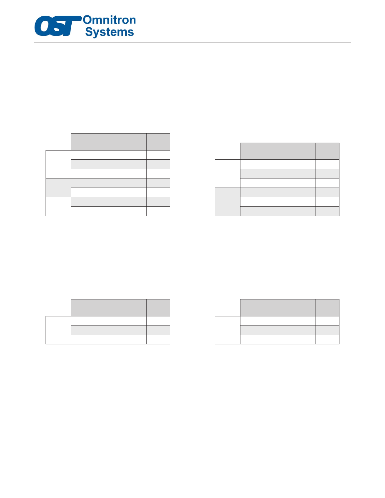
Chassis installation guidelines for the plug-in model numbers listed in Table 1a and 1b are addressed within
this document. Section 2.0 outlines the requirements when using XG plug-in modules and Section 3.0
outlines the requirements when using an XG+ or XGT+ plug-in module.
Plug-in Module
Module Numbers
8599-00 SFP+ SFP+
XG
XG+
XGT+
Table 1a: Discontinued XG/XG+ and Current XGT+ Model Numbers Table 1b: Replacement XG/XG+ Model Numbers
8599-01 SFP+ XFP
8599-11 XFP XFP
8599N-01 SFP+ XFP
8599N-11 XFP XFP
8589N-0 SFP+ RJ45
8589N-1 XFP RJ45
Port 1 Port 2
XG
XG+
Plug-in Module
Module Numbers
8599P-00 SFP+ SFP+
8599P-01 SFP+ XFP
8599P-11 XFP XFP
8599R-00 SFP+ SFP+
8599R-01 SFP+ XFP
8599R-11 XFP XFP
Port 1 Port 2
Standalone modules do not have any power supply or airow restrictions, however, do not cover the fan
or any ventilations holes on the module during the installation. Also, check the individual data sheets for
appropriate transceiver recommendations.
2.0 XG PLUG-IN MODULE REQUIREMENTS
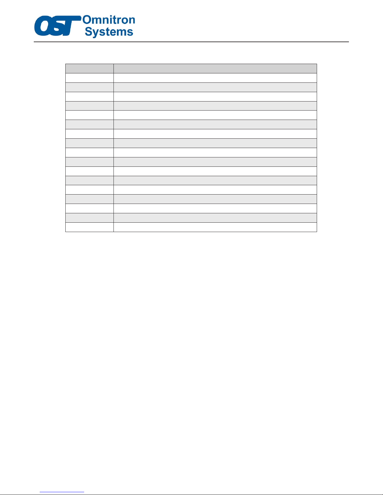
The discontinued and replacement XG plug-in model numbers shown in Table 2a and 2b do not generate
elevated levels of heat, and therefore require no special airow/cooling or spacing requirements.
Plug-in Module
Module Numbers
8599-00 SFP+ SFP+
XG
Table 2a: Discontinued XG Model Numbers Table 2b: Replacement XG Model Numbers
8599-01 SFP+ XFP
8599-11 XFP XFP
Port 1 Port 2
XG
Plug-in Module
Module Numbers
8599P-00 SFP+ SFP+
8599P-01 SFP+ XFP
8599P-11 XFP XFP
Port 1 Port 2
©2018 Omnitron Systems Technology, Inc. – All rights reserved.
Page 3
Page 4
The following chassis are recommended.
Model Number Description
8242-x 1-Module Chassis, 8.3W PS, 100-240VAC
8230-x 2-Module Chassis, 8.5W PS, 100-240VAC
8231-x 2-Module Chassis, 16.5W PS, 100-240VAC, with Temp Controlled Fan
8232-x 2-Module Chassis, 16.5W High Airow PS, 100-240VAC, with Fan
8235-x 2-Module Chassis, 6.6W PS, 18 to 60VDC
8236-x 2-Module Chassis, 16.5W PS, 18 to 60VDC, with Temp Controlled Fan
8238-x 2-Module Chassis, 16.5W High Airow PS, 18 to 60VDC, with Fan
8220-x 5-Module Chassis, 33W PS, 100-240VAC, with Fan
8221-x 5-Module Chassis, 66W High Airow PS, 100-240VAC, with Fan
8226-x 5-Module Chassis, 33W PS, 18 to 36VDC, with Fan
8225-x 5-Module Chassis, 33W PS, 36 to 60VDC, with Fan
8227-x 5-Module Chassis, 66W High Airow PS, 36 to 60VDC, with Fan
8200-x 19-Module Chassis, 60W PS, 100-240VAC, with Fan
8201-x 19-Module Chassis, 120W High AirFlow PS, 100-240VAC, with Fan
8206-x 19-Module Chassis, 66W PS, 18 to 36VDC, with Fan
8205-x 19-Module Chassis, 66W PS, 36 to 60VDC, with Fan
8207-x 19-Module Chassis, 120W High Airow PS, 36 to 60VDC, with Fan
Application Note
Doc. No. 002-A0006
Rev E
Table 3. Recommended Chassis fort XG Modules
Consult the Power Calculator Tool to make sure there is sufcient power to support the installed iConverter
module. If slots are empty, it is recommended that a blank panel (8090-0) is installed ensure even and
consistent airow throughout the chassis.
http://www.omnitron-systems.com/power-calculator
Use the link above to access the online Power Calculator Tool or visit the Support section on Omnitron’s
website. The tool guides the user in selecting the appropriate power supply(s) for the selected chassis, to
ensure sufcient power is available for the selected plug-in module.
NOTES:
1. It is recommended for chassis with fans that all empty slot have a blank panel (8090-0) installed.
2. TheXGmodulecanbeinstalledinHighAirowchassis.
3. Only one XG module can be installed in a 2-Module Chassis listed above. The XG module must be
installed in the bottom slot of the chassis. The top slot can be populated with another iConverter
module, such as the NMM2.
4. A 2-Module Chassis without a fan does not require a blank panel if only one module is installed.
©2018 Omnitron Systems Technology, Inc. – All rights reserved.
Page 4
Page 5
Application Note
Doc. No. 002-A0006
Rev E
3.0 XG+ AND XGT+ PLUG-IN MODULES REQUIREMENTS
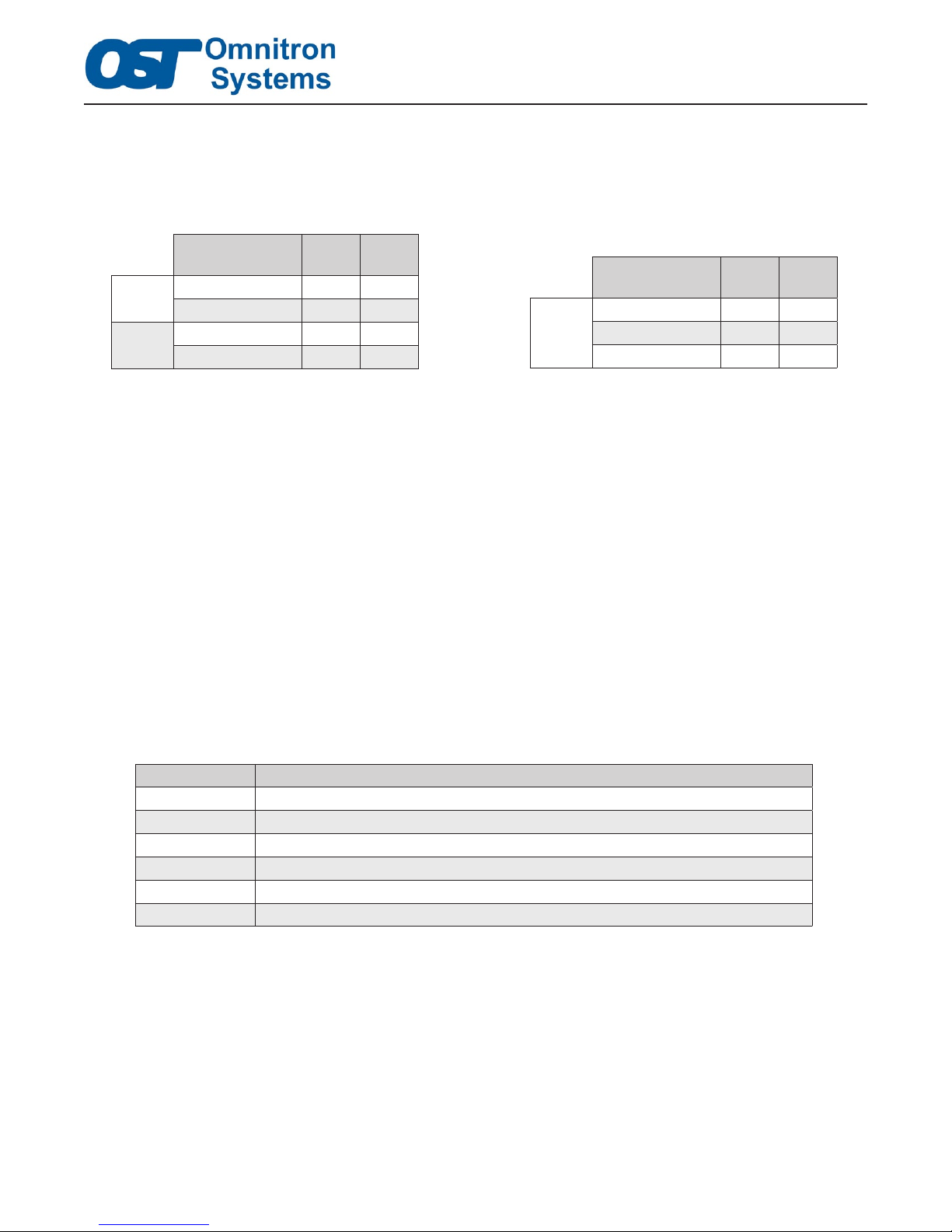
The XG+ and XGT+ models shown in Table 4a and 4b can generate elevated levels of heat depending on
the installed transceivers. The appropriate chassis must be selected to meet the appropriate power and
airow requirements for these modules.
Plug-in Module
Module Numbers
XG+
XGT+
Table 4a: Discontinued XG+ and Current XGT+ Model Numbers Table 4b: Replacement XG+ Model Numbers
8599N-01 SFP+ XFP
8599N-11 XFP XFP
8589N-0 SFP+ RJ-45
8589N-1 XFP RJ-45
Port 1 Port 2
XG+
Plug-in Module
Module Numbers
8599R-00 SFP+ SFP+
8599R-01 SFP+ XFP
8599R-11 XFP XFP
Port 1 Port 2
The Discontinued XG+ module does not have a SFP+/SFP+ model.
Consult the Power Calculator Tool to make sure there is sufcient power to support the installed iConverter
module. If slots are empty it must have a blank panel (8090-0) covering the slot to ensure even and consistent
airow throughout the chassis.
http://www.omnitron-systems.com/power-calculator
Use the link above to access the online Power Calculator Tool or visit the Support section on Omnitron’s
website. The tool guides the user in selecting the appropriate power supply(s) for the selected chassis, to
ensure sufcient power and airow is available for the selected plug-in module.
3.1 Installation Guidelines When Using the 19-Module Chassis
When installed in the iConverter 19-Module Chassis, the XG+ and XGT+ plug-in modules require one or
more 120W High Airow power supplies. These power supplies have high capacity fans which provide
sufcient airow and cooling for the module(s). Table 5 provides the model numbers for the available
19-Module High Airow Chassis.
Model Number Description
8201-1 19-Module Chassis with one (1) 120W High AirFlow PS, 100-240VAC, with Fan
8201-2 19-Module Chassis with two (2) 120W High AirFlow PS, 100-240VAC, with Fan
8201-3 19-Module Chassis with three (3) 120W High AirFlow PS, 100-240VAC, with Fan
8207-1 19-Module Chassis with one (1) 120W High Airow PS, 36 to 60VDC, with Fan
8207-2 19-Module Chassis with two (2) 120W High Airow PS, 36 to 60VDC, with Fan
8207-3 19-Module Chassis with three (3) 120W High Airow PS, 36 to 60VDC, with Fan
Table 5. 19-Module Chassis used with XG+ and XGT+ Modules
When installing XG+/XGT+ modules in the 19-Module Chassis, the slot to the right of the installed XG+/
XGT+ must be empty and a blank panel (8090-0) must be installed over the empty slot. Also, all unused
slots must have a blank panel installed.
Each 120W High Airow power supply can support up to 6 iConverter modules installed in the chassis,
and three of the six modules can be XG+/XGT+. The XG+/XGT+ modules must be installed directly in
front of the installed High Airow power supply and all empty slots must have a blank panel installed. The
other iConverter modules can be installed anywhere in the chassis.
©2018 Omnitron Systems Technology, Inc. – All rights reserved.
Page 5
Page 6
Application Note
Doc. No. 002-A0006
Rev E
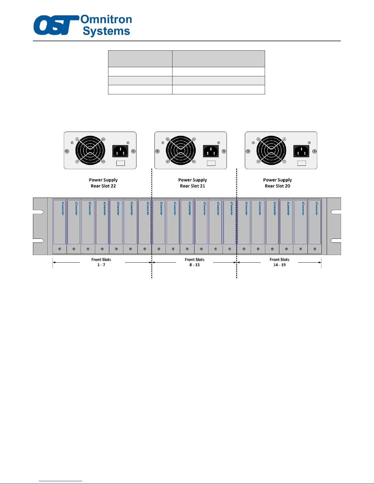
Power Supply
Chassis Slot Number
Slot 20 Slots 14 - 19
Slot 21 Slots 8 - 13
Slot 22 Slots 1 - 7
Table 6. 19-Module Chassis Power Supply and XG+/XGT+ Module Slot Positions
Supported XG+/XGT+ Module
Chassis Slot Numbers
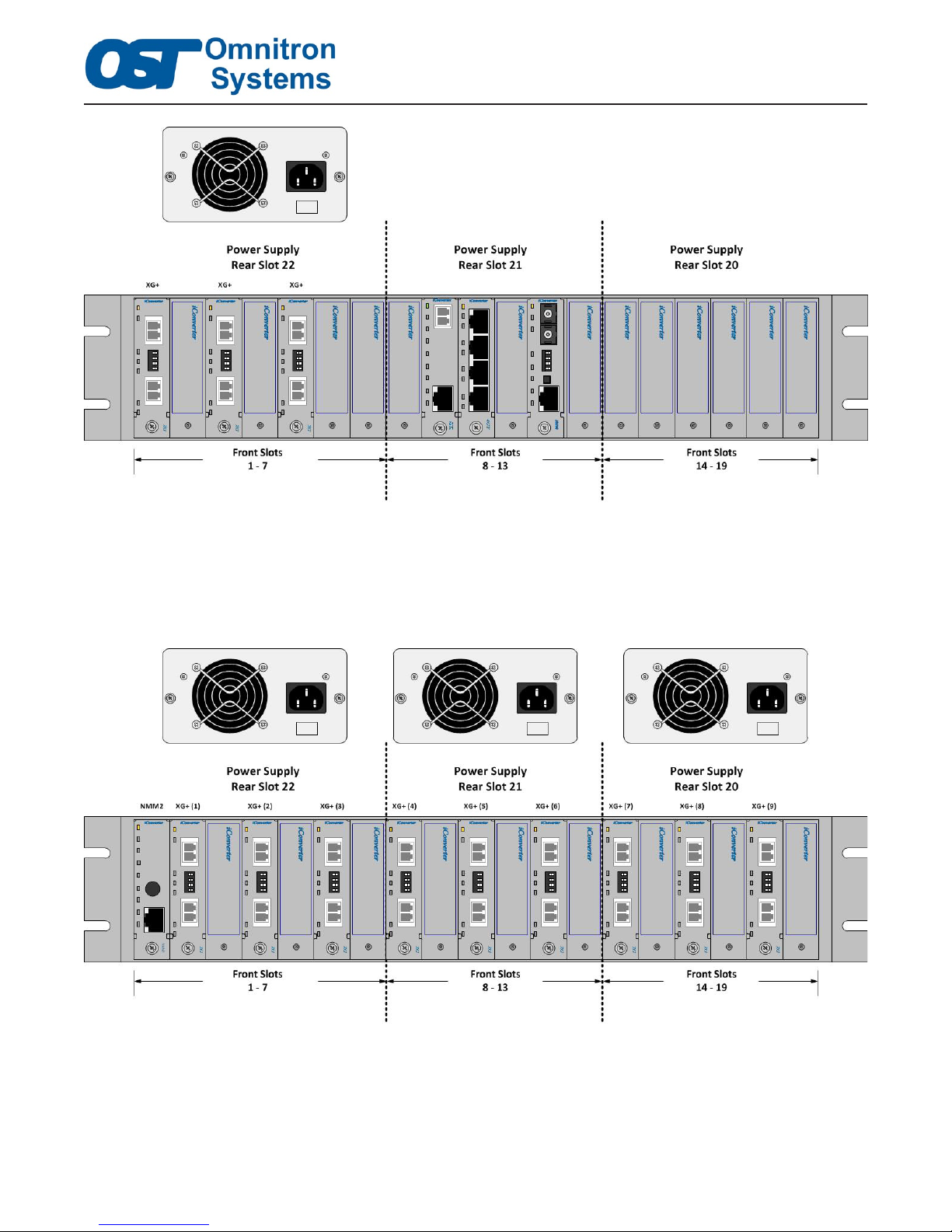
The gure below shows the relationship between the power supply slots and the appropriate slots for the
installed XG+/XGT+ modules.
Figure 1. 19-Module Chassis Power Supplies with Supported Module Slot Positions
Figure 2 shows one (1) 120W High Airow power supply installed in slot 22 and three XG+ modules
installed in the appropriate chassis slots. This conguration will provide sufcient airow and cooling for
the modules. Three additional iConverter modules can be installed anywhere in the chassis that does not
violate the spacing requirements of the XG+ modules.
©2018 Omnitron Systems Technology, Inc. – All rights reserved.
Page 6
Page 7
Application Note
Doc. No. 002-A0006
Rev E
Figure 2. Properly Congured 19-Module Chassis and XG+ Modules
A maximum of nine (9) XG+/XGT+ modules can be installed in a 19-Module Chassis when congured
with three (3) 120W High Airow power supplies installed.
The following gure shows a properly congured 19-Module Chassis fully populated with one NMM2,
nine XG+ modules, blank panels and three 120W High Airow power supplies.
An existing 19-Module Chassis can be retrotted to support the XG+/XGT+ modules by replacing the
power supply in the chassis with 120W High Airow power supplies. The number of 120W High Airow
power supplies required will depend on the number of XG+/XGT+ modules installed. Table 7 provides
the model numbers for the High Airow power supplies available for the 19-Module Chassis.
©2018 Omnitron Systems Technology, Inc. – All rights reserved.
Figure 3. 19-Module Chassis with Nine XG+ Modules
Page 7
Page 8
Application Note
Doc. No. 002-A0006
Rev E
The modules installed in the chassis may need to be repositioned in order to meet the airow and spacing
requirements of the XG+/XGT+ modules as stated in this section.
Model Number Description
8201-9 Spare 19-Module Chassis with one (1) 120W High AirFlow PS, 100-240VAC, with Fan
8207-9 Spare 19-Module Chassis with one (1) 120W High Airow PS, 36 to 60VDC, with Fan
Table 7. 19-Module Chassis Spare Power Supplies
NOTES:
1. All empty or unused slots must have a blank panel installed. This includes all front and rear slots.
2. HighAirowpowersupplies(120W)cannotbeinstalledinthesamechassiswithothertypesof
power supplies.
3. XG modules can be installed into any slot as long as the XG+/XGT+ requirements are maintained.
3.2 Installation Guidelines When Using the 5-Module Chassis
When installed in the iConverter 5-Module Chassis, the XG+ and XGT+ plug-in modules require at least
one (1) 66W High Airow power supply. These power supplies have high capacity fans which provide
sufcient cooling for the module(s). Table 8 provides the model numbers for the available 5-Module High
Airow Chassis.
Model Number Description
8221-1 5-Module Chassis with one (1) 66W High Airow PS, 100-240VAC, with Fan
8221-2 5-Module Chassis with two (2) 66W High Airow PS, 100-240VAC, with Fan
8227-1 5-Module Chassis with one (1) 66W High Airow PS, 36 to 60VDC, with Fan
8227-2 5-Module Chassis with two (2) 66W High Airow PS, 36 to 60VDC, with Fan
Table 8. 5-Module Chassis with High Airow Power Supplies
At least one High Airow power supply must be installed in the chassis.
An XG+/XGT+ module can be installed in any or all slots in the 5-Module Chassis. All empty slots must
have blank panels (8090-0) installed, which will ensure even and consistent airow throughout the chassis.
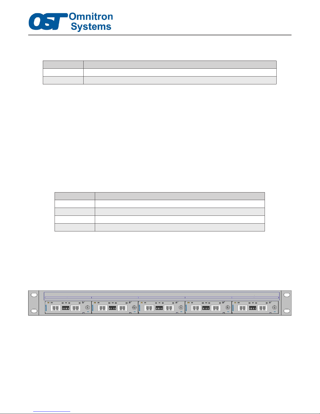
A maximum of ve (5) XG+/XGT+ modules can be installed in a 5-Module Chassis.
The following gure shows a 5-Module Chassis fully populated with ve XG+ modules.
An existing 5-Module Chassis can be retrotted to support XG+/XGT+ modules by replacing the power
supplies in the chassis with 66W High Airow power supplies. The table below indicates the model numbers
for the High Airow power supplies available for the 5-Module Chassis.
©2018 Omnitron Systems Technology, Inc. – All rights reserved.
Figure 4. 5-Module Chassis with Four XG+ Modules
Page 8
Page 9
Application Note
Doc. No. 002-A0006
Rev E
Model Number Description
8221-9 Spare 5-Module Chassis with one (1) 66W High AirFlow PS, 100-240VAC, with Fan
8227-9 Spare 5-Module Chassis with one (1) 66W High Airow PS, 36 to 60VDC, with Fan
Table 9. 5-Module Chassis Spare Power Supplies
NOTES:
1. All empty or unused slots must have a blank panel installed. This includes all front and rear slots.
2. HighAirowpowersupplies(66W)cannotbeinstalledinthesamechassiswithothertypesof
power supplies.
3.3 Installation Guidelines When Using the 2-Module Chassis
When installed in the iConverter 2-Module Chassis, the XG+ and XGT+ plug-in modules require the
16.5W High Airow AC or DC chassis. These chassis utilize a high capacity fan which provides sufcient
cooling for the XG+/XGT+ module. Table 10 provides the model numbers for the available 2-Module
High Airow Chassis.
Model Number Description
8232-1 2-Module Chassis, 16.5W High Airow PS, 100-240VAC, with Fan
8238-1 2-Module Chassis, 16.5W High Airow PS, 18 to 60VDC, with Fan
Table 10. 2-Module Chassis with High Airow Power Supply
Only one XG+/XGT+ module can be installed in a 2-Module High Airow Chassis. The second slot can
be populated with another iConverter module, such as the NMM2 or blank panel (8090-0).
Consult the Power Calculator Tool to makes sure there is sufcient power to support the additional
iConverter module. If the second slot is empty, it must have a blank panel covering the slot to ensure even
and consistent airow throughout the chassis.
http://www.omnitron-systems.com/power-calculator
Use the link above to access the online Power Calculator Tool or visit the Support section on Omnitron’s
website. The tool guides the user in selecting the appropriate chassis, to ensure sufcient power and airow
is available for the selected plug-in module.
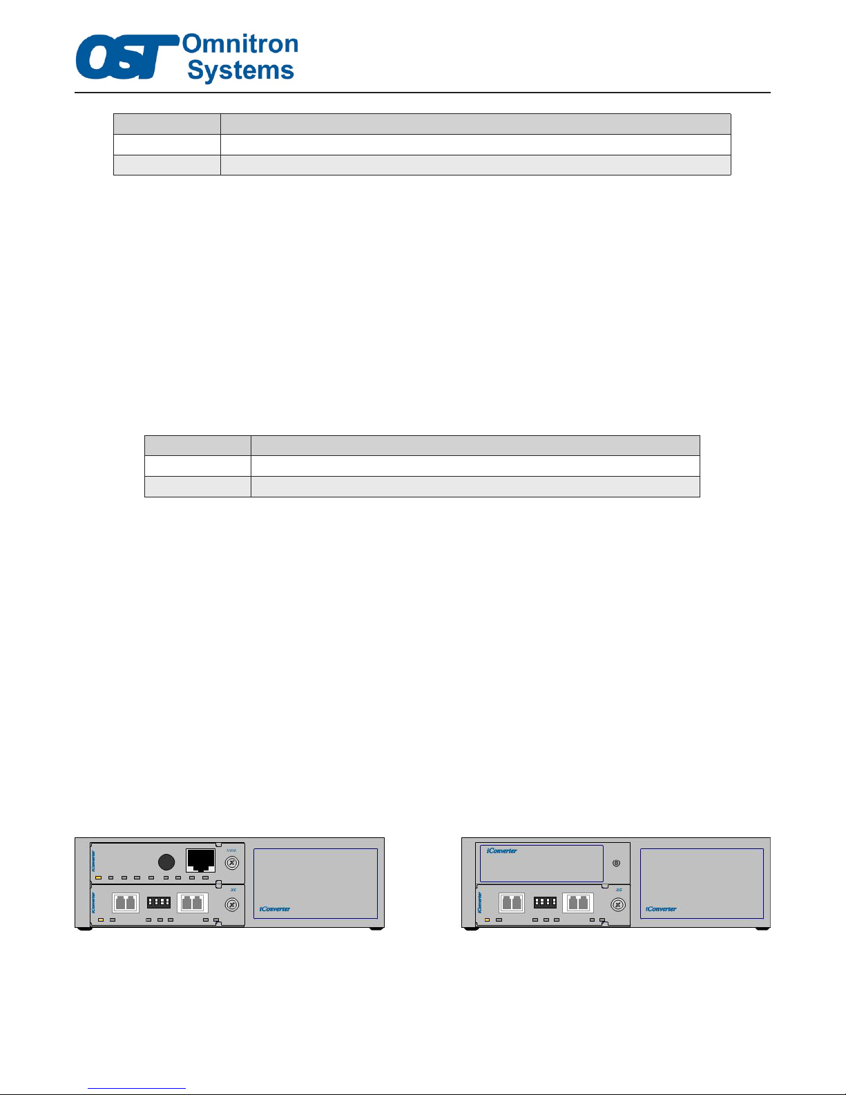
The following gures show properly congured 2-Module High Airow Chassis. The gure on the left
shows a 2-Module High Airow Chassis with an NMM2 module installed in the upper slot and a XG+
module installed in the lower slot. The gure on the right shows a 2-Module High Airow Chassis with a
XG+ module installed in the lower slot and a blank panel installed in the upper slot.
©2018 Omnitron Systems Technology, Inc. – All rights reserved.
Figure 5. 2-Module Chassis with one XG+ Module
Page 9
Page 10

Application Note
Doc. No. 002-A0006
Rev E
NOTES:
1. All empty or unused slots must have a blank panel installed.
2. AnXGmodulecanbeinstalledinaHighAirowchassis.
3. Only one XG+/XGT+ module can be installed in a 2-Module Chassis. The XG+/XGT+ module
must be installed in the bottom slot of the chassis as shown in Figure 5. Another iConverter module
can be installed in the top slot. If the slot is empty, a blank panel (8090-0) must be installed.
3.4 INSTALLATION GUIDELINES WHEN USING THE 1-MODULE CHASSIS
The XG+ and XGT+ plug-in modules are not supported in any iConverter 1-Module Chassis. For this
application, an XG+ or XGT+ Standalone is recommended.
iConverter is a Registered Trademark of Omnitron Systems Technology, Inc. Trademarks are owned by their respective companies. Content is subject to
change without notice.
©2018 Omnitron Systems Technology, Inc. – All rights reserved.
Page 10
 Loading...