

Page 1
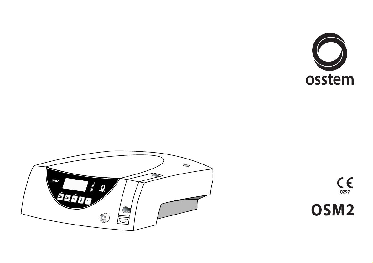
Instructions for use
SI-923 / SI-915
Page 2
2
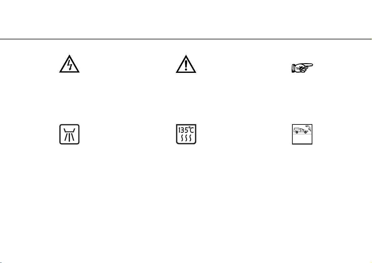
W&H Symbols
WARNING!
(Risk of injury)
ATTENTION!
Important notes!
(to prevent damage occurring)
General explanations,
without risk to
persons or objects
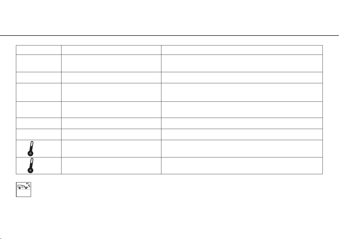
W&H ServiceSterilizable
up to the stated temperature
Thermo washer disinfectable
Only for USA
Caution: Federal law restricts this device to sale by or on the order of a dentist, physician or any other practitioner
licensed by the law of the state in which he or she practices to use or order the use of the device.
Page 3

3
Contents
W&H Symbols ..............................................................................................................................................................2
1. Introduction ............................................................................................................................................................4 – 5
2. Unpacking ....................................................................................................................................................................6
3. Equipment supplied ....................................................................................................................................................7
4. Safety notes ........................................................................................................................................................8 – 10
5. Description of front panel ..........................................................................................................................................11
6. Description of rear panel............................................................................................................................................12
7. Description of motor with cable ................................................................................................................................13
8. Starting operation – General ......................................................................................................................................14
9. Starting operation – Foot control ......................................................................................................................15 – 17
10. Factory settings..................................................................................................................................................18 – 19
11. Control unit operation ........................................................................................................................................20 – 23
12. Error messages ..........................................................................................................................................................24
13. Disinfection, Cleaning, Sterilization....................................................................................................................25 – 27
14. W&H Accessories ..............................................................................................................................................28 – 29
15. Servicing ............................................................................................................................................................30 – 31
16. Technical data ....................................................................................................................................................32 – 33
Letter of indemnity ....................................................................................................................................................35
Certification of Training ........................................................................................................................................37, 39
Authorized W&H Service organizations ............................................................................................................41 – 43
Page 4

4
1. Introduction
For your safety and the safety of your patients
These Instructions for Use explain how to use your product. However, we must also warn against possible
hazardous situations. Your safety, the safety of your team, and of course, the safety of your patients are of
paramount importance to us.
It is therefore essential to read the safety notes on Pages 8 to 10.
Intended use
Mechanical drive unit with coolant supply for transmission instruments with coupling system according to ISO 3964
(DIN 13.940).
The equipment is a drive unit for use in dental surgery, implantology and maxillo-facial surgery for treatment of dental hard
tissue.
Qualifications of the user
Only suitably qualified medical, technical and specialist trained staff may use the dental surgical unit OSM2 from
OSSTEM. We have based our development and design of the OSM2 on the "physician" target group.
Page 5
5
Introduction
Production according to EU Directive
EU Directive 93/42/EEC has been used as a basis in the design and manufacture of this medical product and
this applies to the dental surgical units
– OSM2 SI-915 and
– OSM2 SI-923
in the condition as supplied by us. This declaration does not apply to non-specified fittings, mountings etc.
Responsibility of the manufacturer
The manufacturer can only accept responsibility for the safety, reliability and performance of the OSM2 when there
is compliance with the following directions:
– OSM2 must be used in accordance with these Instructions for Use.
– OSM2 has no components which can be repaired by the user. Assembly, modifications or repairs must only be
undertaken by skilled personnel authorized by W&H.
– The electrical installation at the premises must comply with the regulations of ÖVE-EN 7 ("Installation of
electrical equipment in rooms used for medical purposes") or with the regulations applicable in your country.
– Unauthorized opening of the equipment invalidates all claims under warranty and any other claims.
Page 6
6
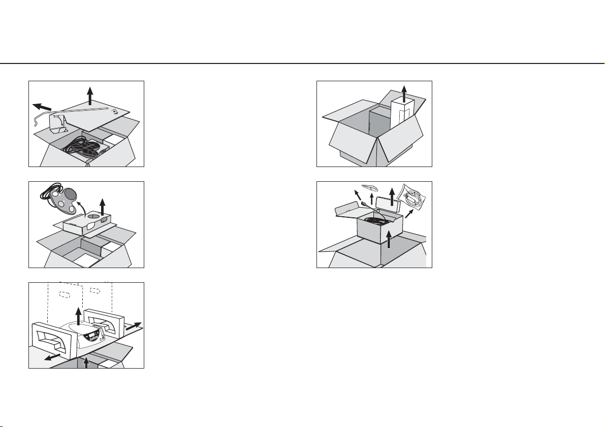
2. Unpacking
The packaging is environmentally friendly and can be
disposed of by industrial recycling companies.
However, we recommend that you keep the original
packaging.
➊ Lift out insert with stand.
➋ Remove foot control and
insert.
➌ Lift out insert with control
unit.
➍ Remove irrigation tubing
set.
➎ Remove carton containing
motor, mains cable,
motor support and
instruments (optional).
Page 7

7
3. Equipment supplied
❍ Control unit REF 05191900 (230 V)
❍ Foot control REF 04785700
❍ Motor with 1.8 m cable including 5 clips, REF 04720024
❍ Mains cable REF 01343700 (Europe)
❍ Motor support REF 04735700
❍ Stand REF 04005900
❍ Locking pins REF 04006800 (2 pcs)
❍ Irrigation tubing set REF 436360 (3 pcs, disposable)
Alternative specification:
❍ Control unit REF 05192000 (115 V)
❍ Mains cable REF 02821400 (USA, CAN, J) / REF 03212700 (UK, IRL) / REF 02909300 (AUS, NZ)
Optional accessories:
❍ Motor protective cover REF 04032600
❍ Sterilization cassette REF 04013500
❍ Transportation case REF 04013600
❍ Trolley white REF 04541900 / 04542100
❍ Trolley, stainless steel, REF 04042600
Page 8

8
4. Safety notes
Please ensure that you carry out the following instructions
– Only fit the handpieces when the motor is at a complete standstill.
– Never touch rotary instruments which are still rotating.
– Never touch the chuck mechanism of straight and contra-angle handpieces while they are still running.
– Always ensure correct operating conditions and that sufficient and adequate cooling is delivered.
– Avoid overheating at the treatment site.
Use only suitable and serviceable tools
Ensure that you comply with the manufacturer's instructions for surgical straight and contra-angle handpieces
with respect to maximum speed, maximum torque, forward and reverse movement.
Inappropriate use
Improper use, in addition to incorrect assembly, installation, modification or repairs of the OSM2 or
non-compliance with our instructions invalidates all claims under warranty and any other claims.
Cardiac pacemaker function
Use of the OSM2 involves the generation of magnetic fields, which are below the interference threshold limit according
to EN 50061 Ad1. Even under adverse conditions, there is no likelihood of serious harm to the patient. The OSM2 is
designed for the intermittent operating mode S3 with an operating time of 4 minutes and a pause time of 10 minutes.
Page 9

9
Safety notes
Danger zones M and G
In accordance with IEC 60601-1 / UL 60601-1, the control unit is not suitable for use in potentially explosive
atmospheres or with potentially explosive mixtures of anaesthetic substances containing oxygen or nitrous oxide.
Control unit
The control unit is classed as "conventional equipment" (closed equipment without protection against the ingress of
water).
The OSM2 Program 4 is only designed to be used with the contra-angle handpieces WS-75 E/KM and
WI-75 E/KM approved by W&H. Use of other contra-angle handpieces may result in deviation from the indicated
torques and is under the user’s responsibility. The specified transmission ratios for the Programs
1 to 5 must always be considered.
Motor and foot control
The motor and foot control are approved for use in zone M (AP).
Please note that at low speeds, it is more difficult to determine that the motor is running.
Mains cable
Only connect to an earthed socket outlet.
Power failure
In the event of a power failure, if the OSM2 is switched off, or when alternating between programs, the last values set are
saved and re-activated on power-up.
Page 10

10
Safety notes
System failure
A total system failure of the OSM2 does not constitute a critical fault.
Intermittent operating mode S3 (4min/10min)
When there is a current consumption of max. 0.8 A for SI-923 and 1.6 A for SI-915 (with pump switched on), the
permissible relative load time is 4 minutes to 10 minutes pause time.
Coolant
The OSM2 is designed for use with physiological saline solution. Use only suitable irrigation fluids and comply
with the medical data and instructions from the manufacturer. Use the W&H irrigation tubing set or accessories
approved by W&H. Coolant bottle or coolant bag can be obtained from a pharmacist.
Sterility of irrigation tubing set
Sterile irrigation tubing sets are supplied with the equipment. These irrigation tubings are disposable articles and
must be thrown away after each treatment! Please note the expiry date and the relevant regulations for disposal
of irrigation tubing.
Rotational energy
Fast deceleration of the bur can, at times, cause the selected torque to be overloaded as a result of the rotational
energy stored in the drive system. We therefore advise compliance with the individual manufacturer's instructions
for use, particularly when adjusting superstructure screws. For safety reasons, these should be screwed in very
carefully by hand, or by using a torque wrench. We would point out that adjusting these screws with an electric
motor represents a potential risk as described above.
Page 11
11
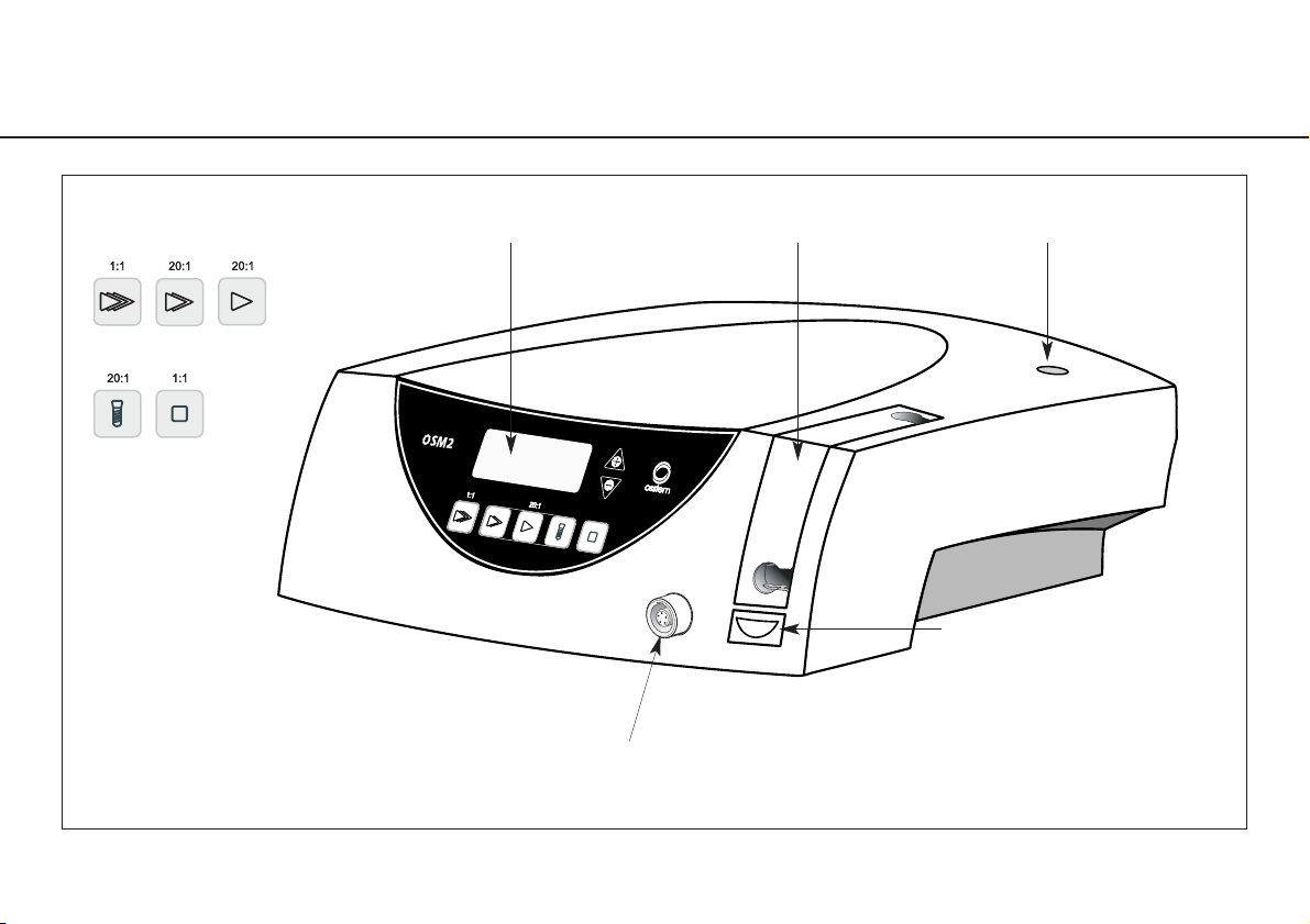
5. Description of front panel
Motor connection socket
Display
OPEN
Pump arm
Pump arm Stand holderProgram buttons
P1 P2 P3
P4 P5
Page 12
12
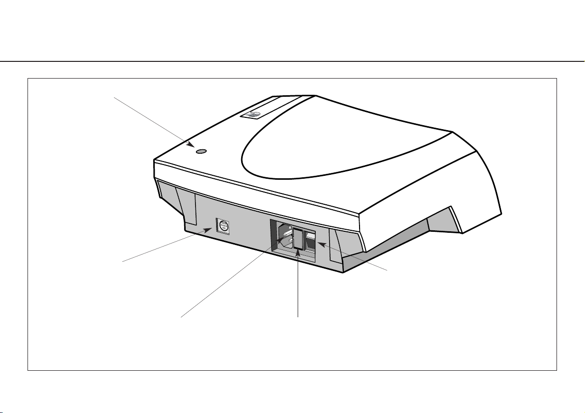
6. Description of rear panel
Connecting socket
for foot control
Fuse holder with 2 fuses REF 04014700
(250 V – 1.25A slow-blow)
Power socket
Power switch
ON / OFF
Stand holder
Page 13
13
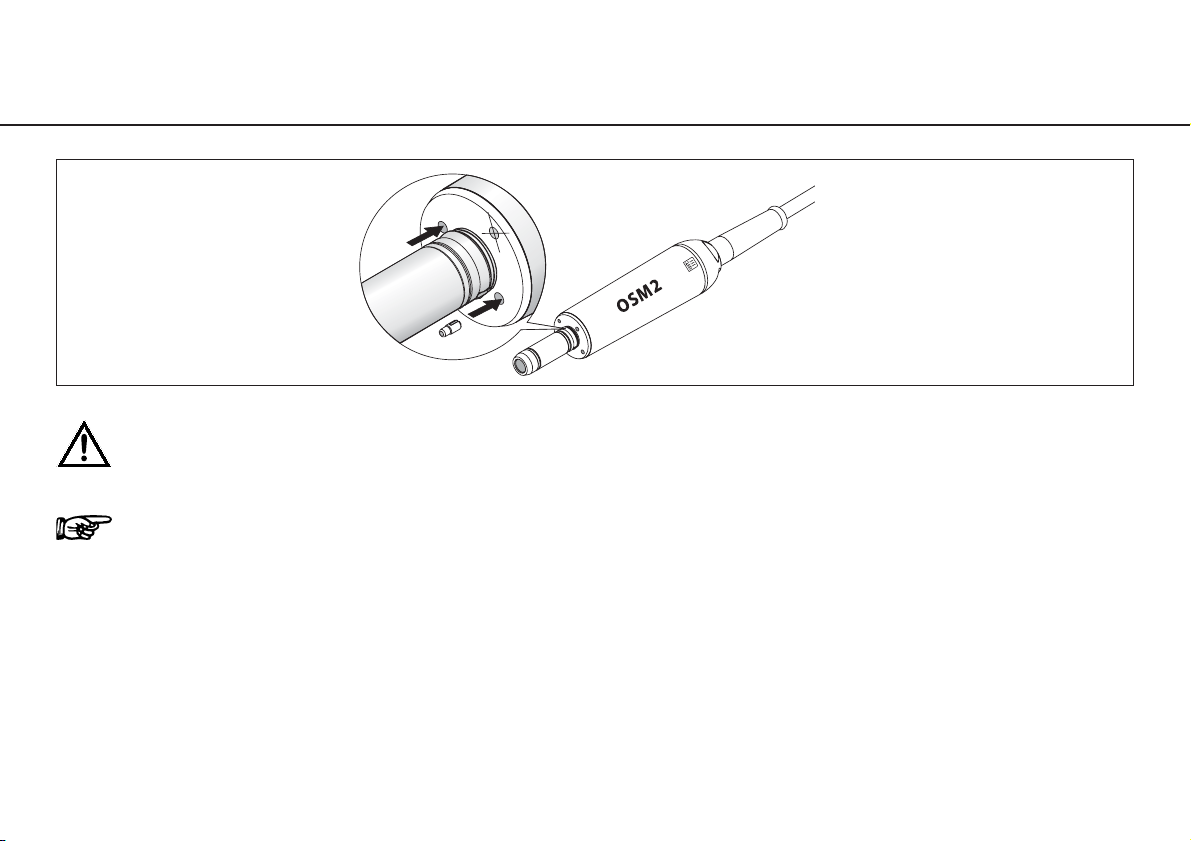
7. Description of motor with cable
The motor may not be dismantled!
The motor bearings are lubricated for life. No oil lubrication or other maintenance is necessary.
To prevent the instrument on the motor attachment from turning during the transmission, the locking pin supplied
can be pushed into one of the two holes (see illustration). The locking pins can only be used in combination with
straight and contra-angle handpieces that have corresponding holes.
Test run
– Start the motor.
– If you observe dysfunctions (e.g. vibrations, unusual noise, overheating, coolant supply failure or leakage) contact your
authorized service organization (see Page 41 – 43).
Page 14
14
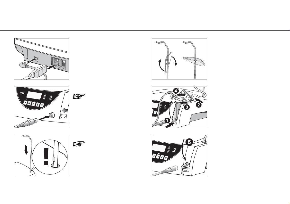
8. Starting operation – General
➊ Connect the mains cable
and foot control.
➋ Connect the motor cable.
Note the positioning!
➌ Insert the stand.
Note the positioning!
➍ Place the motor support
on the stand and rotate it
to fix in place.
➎ Fit the irrigation tubing
set.
➏ Close pump arm.
Page 15
15
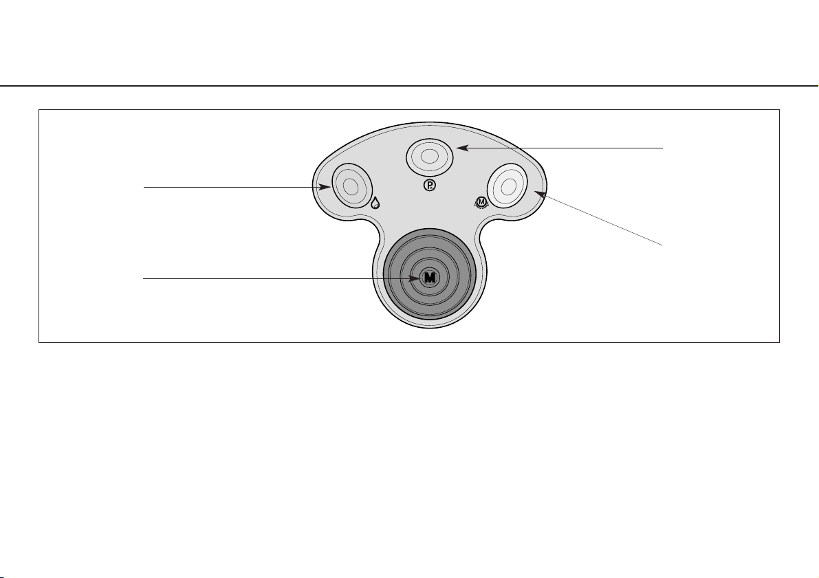
9. Starting operation – Foot control
GREEN
Pump ON / OFF
ORANGE
Change program
YELLOW
Change motor direction
BLACK
Start motor
Operation
BLACK = VARIABLE or ON / OFF (Factory setting = variable)
GREEN = Pump ON / OFF
ORANGE = Program 1 to 5
YELLOW = Motor forward / reverse drive
Page 16

16
Starting operation – Foot control
Changing program
The Programs 1 – 5 can be selected in ascending sequence by operating the ORANGE button.
When changing from Program 5 to Program 1, a longer confirmation signal is heard.
With each program change, the speed is automatically set to forward operation.
Pump ON / OFF
Only when the motor is stationary can the pump be switched on or off by operating the GREEN button of the foot control.
When pump operation is active, the pump symbol appears on the display.
Reverse operation
You can switch between forward and reverse operation by pressing the YELLOW button. On selecting reverse operation,
an audible signal can be heard and the selected Program button flashes. Before the motor starts in reverse operation,
3 audible warning signals are given.
Page 17
17
Starting operation – Foot control
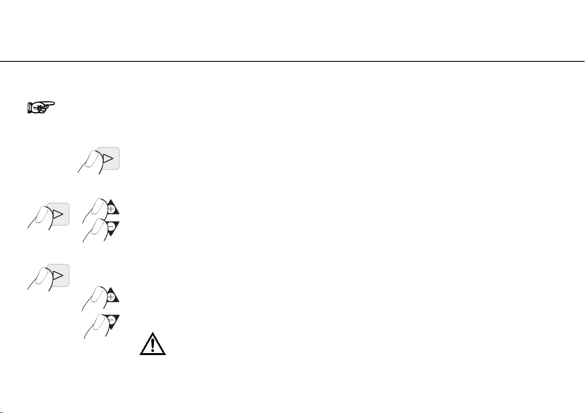
To change from VARIABLE to ON / OFF
Keep Program button P3 depressed throughout this procedure!
➊ Press P3 for approx. 4 seconds
➋ Keep P3 depressed and simultaneously press
PLUS and MINUS
➌ Keep P3 depressed and carry out adjustment.
01 = VARIABLE (factory setting) – Press PLUS button
00 = ON / OFF – Press MINUS button
After changeover the Program button P3 illuminates and is active!
Page 18
18
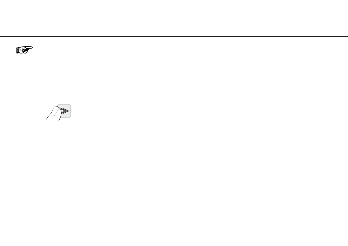
10. Reset factory settings
➊ Switch off the control unit
➋ Keep P1 depressed and simultaneously
switch on the control unit
➌ Keep P1 depressed as long as on the display
the adjustment “DE FAU” appears
Factory setting always starts with Program 1 (P1).
Page 19
19
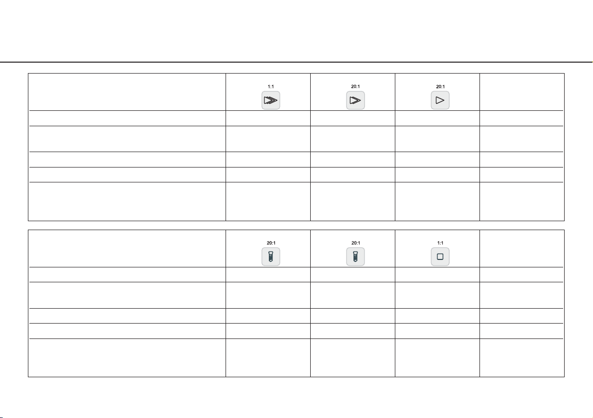
Factory settings (P1 – P5)
P1 P2 P3
Transmission ratio 1:1 20:1 20:1
Factory setting rpm 35 000 1 200 800
Adjustable range rpm 300 – 40 000 15 – 2 000 15 – 2 000
Motor direction forward forward forward
Pump on on on
Factory setting Ncm max. max. max.
Adjustable range Ncm – – –
Intermediate stage Ncm – – –
P4 forward P4 reverse P5
Transmission ratio 20:1 20:1 1:1
Factory setting rpm 15 30 35 000
Adjustable range rpm – – 300 – 40 000
Motor direction forward reverse forward
Pump on off on
Factory setting Ncm 20 50 max.
Adjustable range Ncm 5 – 50 5 – 50 –
Intermediate stage Ncm 32 32 –
Page 20
20
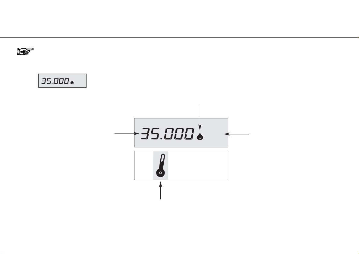
11. Control unit operation – Changing the program (P1 – P5)
Activate the required Program (P1 – P5) by pressing the corresponding Program button. During selection an
audible signal can be heard and the Program button is illuminated. On the display the selected Program appears
with the adjusted range in rpm, e.g. for P1:
Display adjustments
– P1–P3,P5 speed
– P4 torque
Pump operation
ON / OFF
Display adjustments
– P4 torque in Ncm
– P1–P3,P5 speed in rpm
Error messages
– Motor temperature too high
– Motor connection
rpm
Ncm
rpm
Page 21
21
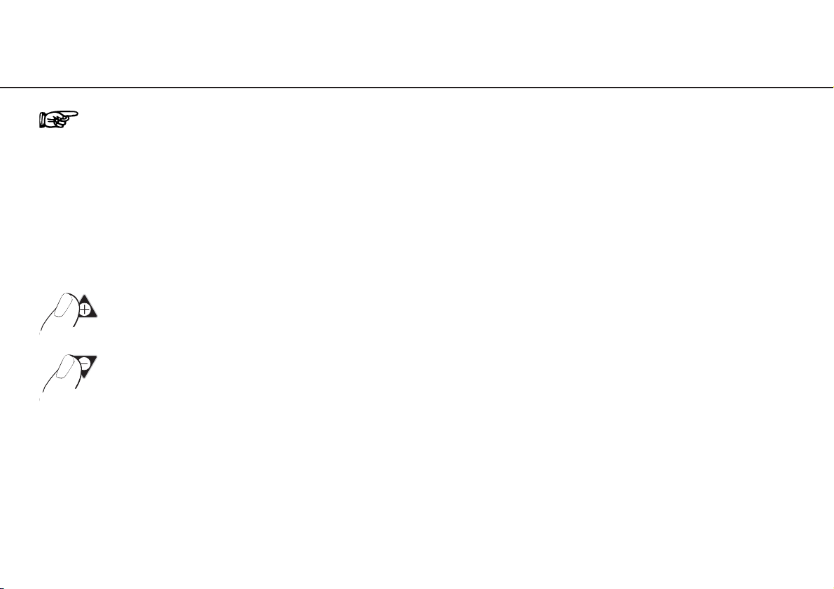
Control unit operation – Changing the speed (P1 – P3, P5)
Keeping PLUS / MINUS depressed activates the repeat function and the values are
continuously increased / decreased.
➊ Press Program button (P1–P3, P5)
➋ Increase speed
➋ Decrease speed
Page 22
22
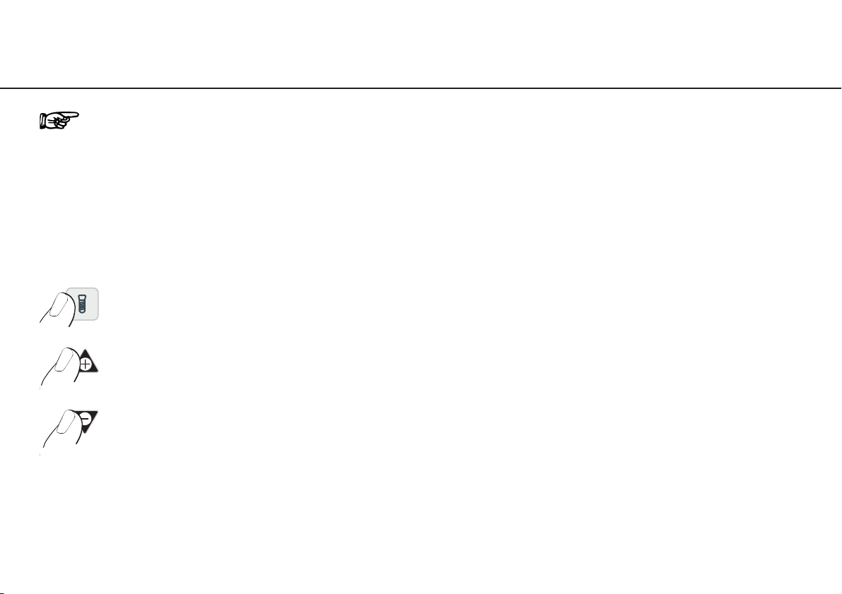
Control unit operation – Changing the torque (P4)
Adjustable range from 5 up to 50 Ncm, intermediate stage 32 Ncm. Keeping PLUS / MINUS depressed activates
the repeat function and the values are continuously increased / decreased.
When changing from 5 to 50 Ncm and 50 to 5 Ncm, a longer confirmation signal is heard.
When the adjustable torque in the forward/reverse drive mode is reached, the motor switches off automatically.
➊ Press Program button P4
➋ Increase torque in 5-Ncm-steps
➋ Decrease torque in 5-Ncm-steps
Page 23
23
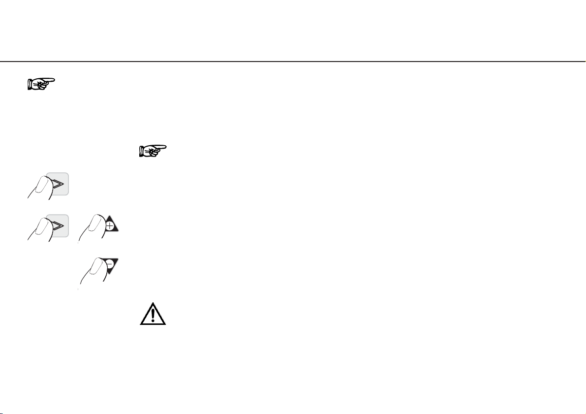
Control unit operation – Changing the coolant flow (P1 – P5)
Factory setting 100 %. Adjustable range 65 %, 80 % and 100 %.
Depressing PLUS / MINUS the values are continuously increased / decreased.
➊ Keep P2 depressed for approx. 4 seconds
(the adjusted coolant flow rate appears)
➋ Keep P2 depressed and press PLUS button
to increase flow rate
➋ Keep P2 depressed and press MINUS button
to decrease flow rate
After adjustment, the Program button P2 illuminates and is active!
Keep Program button P2 depressed throughout this procedure!
Page 24
24
12. Error messages
Error No. Description Remedy
00 Electronics overheating – Switch off the equipment, allow to cool
safety shutdown for at least 10 minutes, then re-start
01 Electronics overloaded Switch off the equipment and then re-start
07 Foot control error – Switch off the equipment, re-start, do not
initializing actuate foot control when switching on
09 Foot control error Switch off the equipment, check connection
of the foot control, then re-start
19 Run limiting control Switch off the equipment and re-start
99 System failure Switch off the equipment and re-start
Motor temperature too high Switch off the equipment, allow motor to cool
for at least 10 minutes, then re-start
Motor connection – Switch off the equipment, check motor connection,
safety shutdown then re-start
If one of the error messages described above cannot be rectified by switching off the OSM2 and then switching
it on again, the equipment must be checked by a service and repair organization authorized by W&H
(see Page 41 – 43). If a total failure of the equipment occurs caused by external circumstances, the equipment
must be switched off and then on again.
Page 25
25
13. Disinfection, Cleaning, Sterilization
Follow your country-specific directives, standards and guidelines for disinfection, cleaning and sterilization.
– Wear protective clothing.
– Disinfect and clean the motor immediately after every treatment!
– Sterilize the motor following disinfection and cleaning.
– Sterilize motor with cable and motor support prior to every use.
Control unit, foot control
Pre-disinfection
– If heavily soiled: Clean first with disinfectant cloths.
Manual cleaning and disinfection
The front panel of the control unit and the foot control are sealed and may be wiped clean.
– Disinfection with surface disinfectants, wiping disinfection is recommended.
– Use only surface disinfectants which do not contain chlorine and which are certified by officially recognized institutes.
For USA: Use EPA registered surface disinfectants.
– Note the dosage and the action time of the surface disinfectants used!
Page 26
26
Disinfection, Cleaning, Sterilization
Motor with cable
Do not twist and kink the motor cable! Do not coil it too tightly! This instruction is not necessary when a sterilization cassette
is utilized (optional accessory).
Pre-disinfection
– If heavily soiled: Clean first with disinfectant cloths.
Manual cleaning
– Rinse under demineralized water (< 38 °C) with the aid of a brush (not recommended in U.K.)
– Then remove any liquid residues (absorbent cloth, blow dry with compressed air)
Disinfection
– Disinfection with surface disinfectants, wiping disinfection is recommended.
– Use only surface disinfectants which do not contain chlorine and which are certified by officially recognized institutes.
For USA: Use EPA registered surface disinfectants.
– Note the dosage and the action time of the surface disinfectants used!
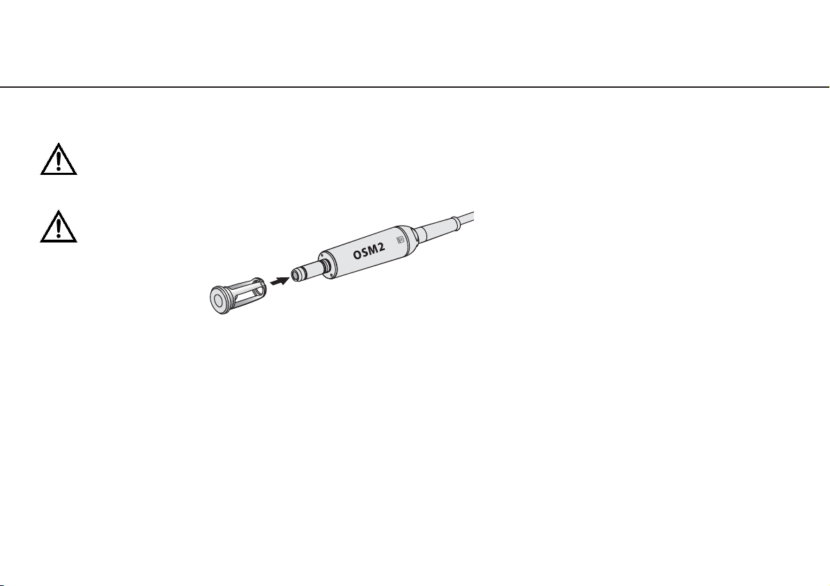
Before disinfection and cleaning
push the motor protective cover
onto the motor attachment!
Page 27
27
Disinfection, Cleaning, Sterilization
Sterilization and storage
W&H recommends sterilization according to EN 13060, class B
– Note the instructions of the unit manufacturer.
– Clean before sterilizing.
– Wrap motor and accessories in sterile goods packing according to EN 868-5.
– Make sure that you only remove dry sterile goods.
– Store sterile goods dust-free and dry.
For sterilization with a drying program: Remove the motor protective cover.
For sterilization without a drying program: Use the motor protective cover (see Page 26).
Approved sterilization procedures
Follow your country-specific directives, standards and guidelines.
Steam vacuum sterilization according to EN 13060, using a sterilization holding time of a minimum of
3 minutes at 134 (+ 3) °C (273.2 + 5.4 °F)
or
Steam gravity sterilization using a sterilization holding time of a minimum of 3 minutes at 134 (+ 3) °C (273.2 + 5.4 °F)
Before starting operation again
Wait until the motor and cable are completely dry.
Moisture in the plug or motor can lead to a malfunction! (Risk of short circuit)
Page 28
28
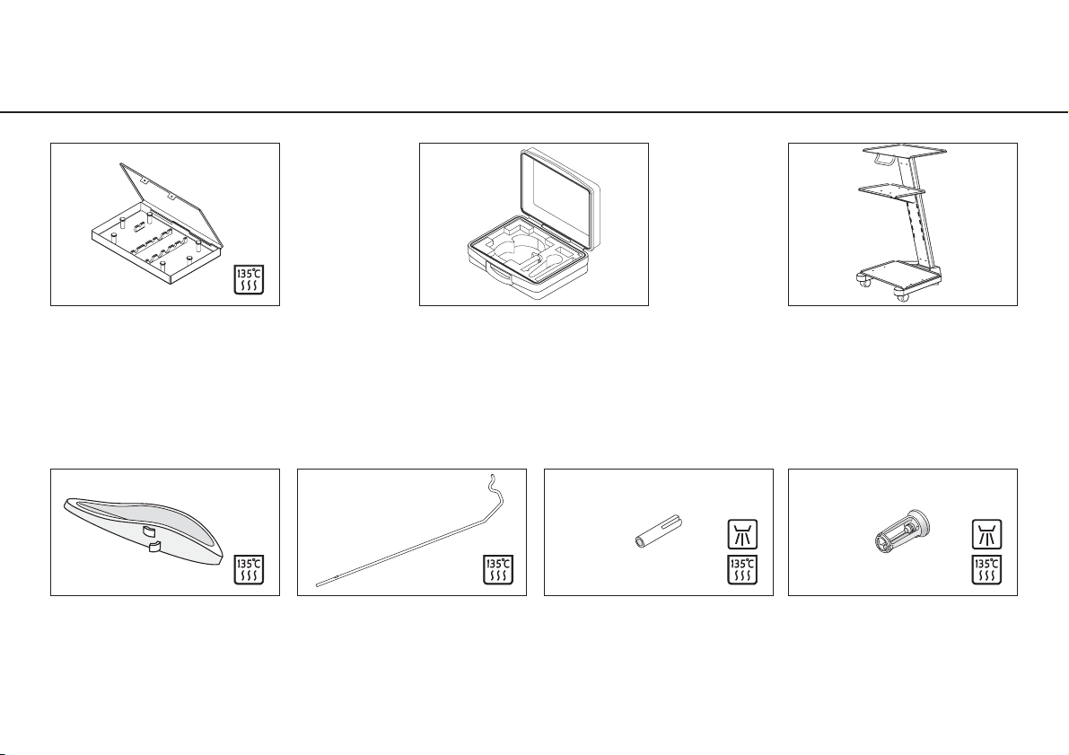
14. W&H Accessories
Use only original W&H accessories/spare parts
or accessories approved by W&H
04735700
Motor support
04005900
Stand
04013500
Sterilization cassette
04013600
Transportation case
04541900 / 04542100
Trolley white
04042600
Trolley, stainless steel
04032600
Motor protective cover
04006800
Locking pin
Page 29
29
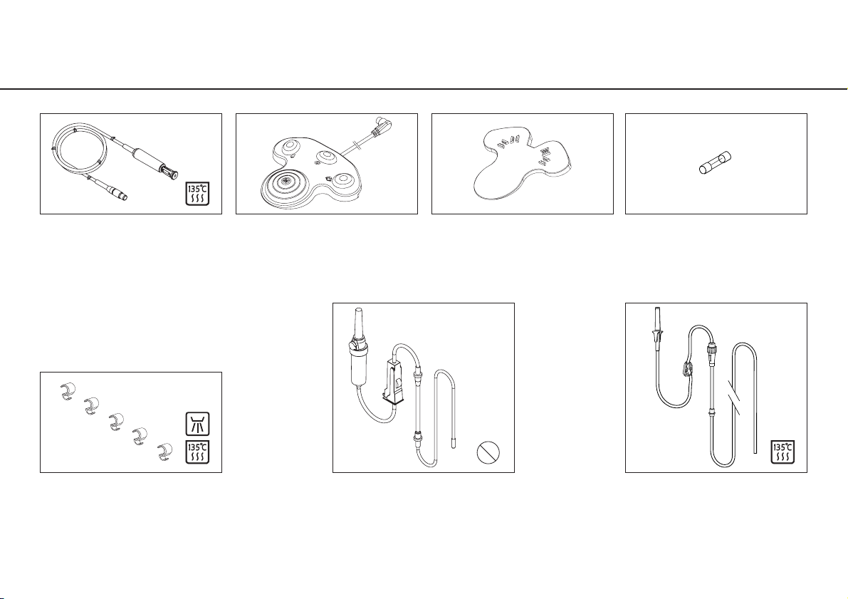
W&H Accessories
04720024
Motor with 1.8 m cable
04785700
Foot control
04019000
Clips (5 pcs)
04363600
Irrigation tubing set 2.2 m (6 pcs)
04719400
Irrigation tubing set 2.2 m
Disposable article
04014700
Fuse 1.25A slow-blow
04308700
Step wedge for foot control
2
Page 30

30
15. Servicing
Regular checking of OSM2 and accessories
Regular servicing of function and safety of the OSM2 including the accessories is necessary and should be carried
out at least once every three years, unless shorter intervals are prescribed by law. The inspection must be
undertaken by a qualified organization and needs to include the following procedures:
– visual inspection for outside damage
– measurement of enclosure leakage current
– measurement of patient leakage current
– visual inspection of internal components and electronic boards on suspicion of safety interference,
e. g. mechanical damage of the enclosure or indicators for overheated or burned (electronic) components
We recommend that only skilled personnel authorized by W&H should undertake this servicing and checking.
Page 31

31
Servicing
Motor and cable
The standard ISO 11498 stipulates a durability of at least 250 sterilization cycles. In the case of the motor and cable from
W&H, regular servicing is specified only after 500 sterilization cycles, or one year.
Repairs
If a defect occurs, always return all the equipment, due to the fact that with motor malfunctions, an inspection of the
electronic controls is also necessary!
Returns
– Refer all questions to your authorized dental dealer or to one of our service organizations (see Page 41 – 43).
– Always return equipment in the original packaging!
– Do not coil the cable around the motor and do not twist or kink the motor cable! (Risk of damage)
Page 32

32
16. Technical data
OSM2 SI-923 SI-915
Supply voltage: 220 – 240 V 100 – 130 V
Rated current: 0.1 – 0.8 A 0.2 – 1.6 A
Permitted voltage fluctuation: ± 10 % ± 10 %
Frequency: 50 – 60 Hz 50 – 60 Hz
Max. mechanical output power: 70 W 70 W
Max. torque on the motor: 5.5 Ncm 5.5 Ncm
Max. coolant in ml (with hose ø 6/4): approx. 100 ml/min approx. 100 ml/min
Fuses: 2x 250 V – 1.25A slow-blow 2x 250 V – 1.25A slow-blow
Operating mode: S3 (4min/10min) S3 (4min/10min)
Dimensions in mm (WxDxH): 252 x 254 x 90 252 x 254 x 90
Weight in kg: 3.30 3.30
The foot control is water-tight according to IPX8, 1m depth of immersion, 1 hour
(water-tight according to IEC 60529)
Equipment of Protective Class II (type of protection against electric shock)
Type BF appliance (not suitable for intracardiac application)
Motor REF 04720024 and foot control REF 04785700 conform to Class AP
according to IEC 60601-1 / UL 60601-1 in danger zone M.
Classification according to § 5 of the General Specifications for the Safety of Medical Electrical Equipment
according to IEC 60601-1 / UL 60601-1
Page 33

33
Technical data
Physical characteristics
Temperature in storage: -40 °C (-40 °F) to +70 °C (+158 °F)
Air humidity in storage: 8 % to 80 % (relative), non-condensing at +40 °C (+104 °F)
Temperature in operation: +10 °C (+50 °F) to +40 °C (+104 °F)
Air humidity in operation: 15 % to 80 % (relative), non-condensing at +40 °C (+104 °F)
Recycling
W&H considers that it has a special duty towards the environment. The OSM2 equipment along with its packaging has
been designed to be as environmentally friendly as possible.
Disposal of the OSM2 (control unit), foot control and motor
Follow your country-specific laws, directives, standards and guidelines for the disposal of used electrical devices.
Disposal of the packaging material
All packaging materials have been selected according to environmentally compatible and disposal aspects and can be
recycled. Please send old packaging materials to the relevant collection and reprocessing system. In this way, you will
contribute to the recycling of raw materials and the avoidance of waste.
Page 34

Page 35

This W&H product has been manufactured with great care by highly qualified
specialists. A wide variety of tests and controls guarantee faultless operation.
Please note that claims under warranty can only be validated when all the
directions in the instructions for use have been followed.
As manufacturer, W&H is liable for material or manufacturing defects within
a warranty period of one year from the date of purchase.
We accept no responsibility for damage caused by incorrect handling or by
repairs carried out by third parties not authorized to do so by W&H!
High-pressure bulbs are excluded from the warranty.
Claims under warranty – accompanied by proof of purchase – must be sent to
the vendor or to an authorized W&H service point. The provision of service under
warranty extends neither the warranty period nor any other guarantee period.
Letter of indemnity
year warranty
Page 36

Page 37
Copy for the user / customer
CERTIFICATION OF TRAINING
essential for EU user / customer
The user / customer has been trained in all functions of the surgical unit in
accordance with current Instructions for Use. Particular attention was shown to
Safety notes, Disinfecting, Cleaning, Sterilization and Servicing.
W&H Surgical unit
Type SN
wh.com
Name of the user / customer
Clinic, Department
Address
Signature
Name of the instructor
Address
Date Signature
Page 38

Page 39
Copy for the Medical Device Consultant
CERTIFICATION OF TRAINING
essential for EU user / customer
The user / customer has been trained in all functions of the surgical unit in
accordance with current Instructions for Use. Particular attention was shown to
Safety notes, Disinfecting, Cleaning, Sterilization and Servicing.
W&H Surgical unit
Type SN
wh.com
Name of the user / customer
Clinic, Department
Address
Signature
Name of the instructor
Address
Date Signature
✄✄ ✄✄
Page 40

Page 41

41
Authorized W&H Service organizations
W&H Deutschland GmbH & Co.KG, Raiffeisenstraße 4, D-83410 Laufen/Obb.,
Tel. +49 (0)8682 / 89 67-0, Fax +49 (0)8682 / 89 67-11, E-mail: [email protected]
W&H CH-AG, Aathalstrasse 84, CH-8610 Uster ZH,
Tel. +41 (0)43 / 497 84 84, Fax: +41 (0)43 / 497 84 88, E-mail: [email protected]
W&H Dentalmechanik GmbH, Ignaz-Glaser-Straße 60, A-5111 Bürmoos,
Tel. +43 (0)6274 / 6236-239, Fax: +43 (0)6274 / 6236-890, E-mail: [email protected]
CH
A
D
W&H FRANCE S.A.R.L., 4, rue Ettore Bugatti, F-67201 Eckbolsheim,
Tél. : +33 (0)388 774 796 (SAV), Fax : +33 (0)388 774 799, E-mail : [email protected]
F BNL
Page 42
42
Authorized W&H Service organizations
W&H ITALIA Srl, Viale A. Volta 83, I-20090 Cusago,
Tel. +39 / 02 / 90 39 271, Fax: +39 / 02 / 90 39 27 65, E-mail: [email protected]
W&H NORDIC AB, Tillverkarvägen 6, S-187 66 Täby,
Tel. +46 (0)8 / 445 88 30, Fax +46 (0)8 / 445 88 33, E-mail: [email protected]
I
WEHADENT IBÉRICA S.L.,
C/ Ciudad de Melilla, 3, Bajo, E-46017 Valencia, Tel.: +34 / 96 / 353 2020, Fax: +34 / 96 / 353 2579, E-mail: [email protected]
E P
DK FIN IS N S ET LT LV
América
Latina
W&H (UK) LIMITED, 6 Stroud Wood Business Centre, Park Street, St. Albans, Herts AL2 2NJ,
Phone: +44 (0) 1727 874990, Fax: +44 (0) 1727 874628/872254, E-mail: [email protected]
GB IRL M
Page 43

43
Authorized W&H Service organizations
In other countries please contact
W&H Dentalmechanik GmbH, Ignaz-Glaser-Straße 60, A-5111 Bürmoos,
Tel. +43 (0)6274 / 6236-239, Fax: +43 (0)6274 / 6236-890, E-mail: [email protected]
W&H Impex, 7475 Tecumseh RD.E., Windsor, Ontario, N8T 1G2,
Phone: +1 / 519 / 944 67 39, Fax: +1 / 519 / 974 61 21, e-mail: [email protected]
USA CAN
OSSTEM IMPLANT Co., Ltd., 8th FL, WorldMeridian Venture Center II, 426-5, Gasan-dong, Geumcheoun-gu, Seoul 153-803
Phone: +66-82-2-2125-3687, 3633, Fax: +66-82-2-2016-7001, E-mail: [email protected]
ROK
Page 44
Form-Nr. 50589 AEN
Rev. 000 / 24.07.2005
Subject to alterations
W&H Dentalwerk Bürmoos GmbH
Austria, A-5111 Bürmoos
Postfach 1, Ignaz-Glaser-Straße 53
+43 / 6274 / 6236-0
+43 / 6274 / 6236-55
[email protected]
wh.com
Manufacturer
ISO 13485, Annex II
93/42/EWG, EC 0297
Distribution
OSSTEM IMPLANT Co., Ltd.
8th FL, WorldMeridian Venture Center II,
426-5, Gasan-dong, Geumcheon-gu,
Seoul 153-803, Korea
Tel. +66-82-2-2125-3687, 3633 / Fax. +66-82-2-2016-7001 /
[email protected] / www.osstem.com
 Loading...