

Page 1
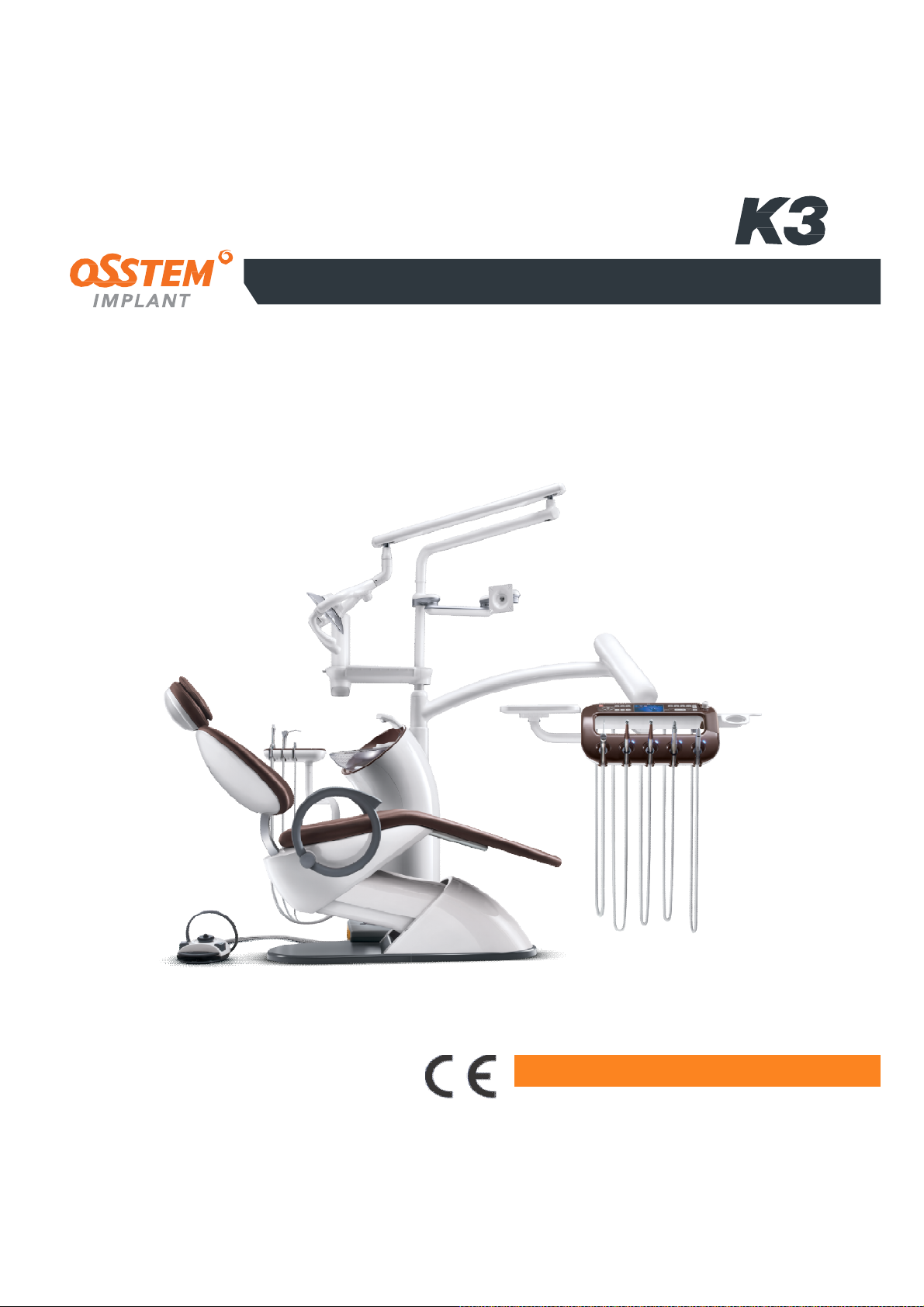
UNIT CHAIR
Dental Unit and Chair
User Manual
OS-UM-C002 ver.2
2460
IMPORTANT NOTES
Please read this manual thoroughly before
using the equipment to ensure safe and
correct usage.
Page 2
Check the matters below
Before you read this user manual
before reading this user manual
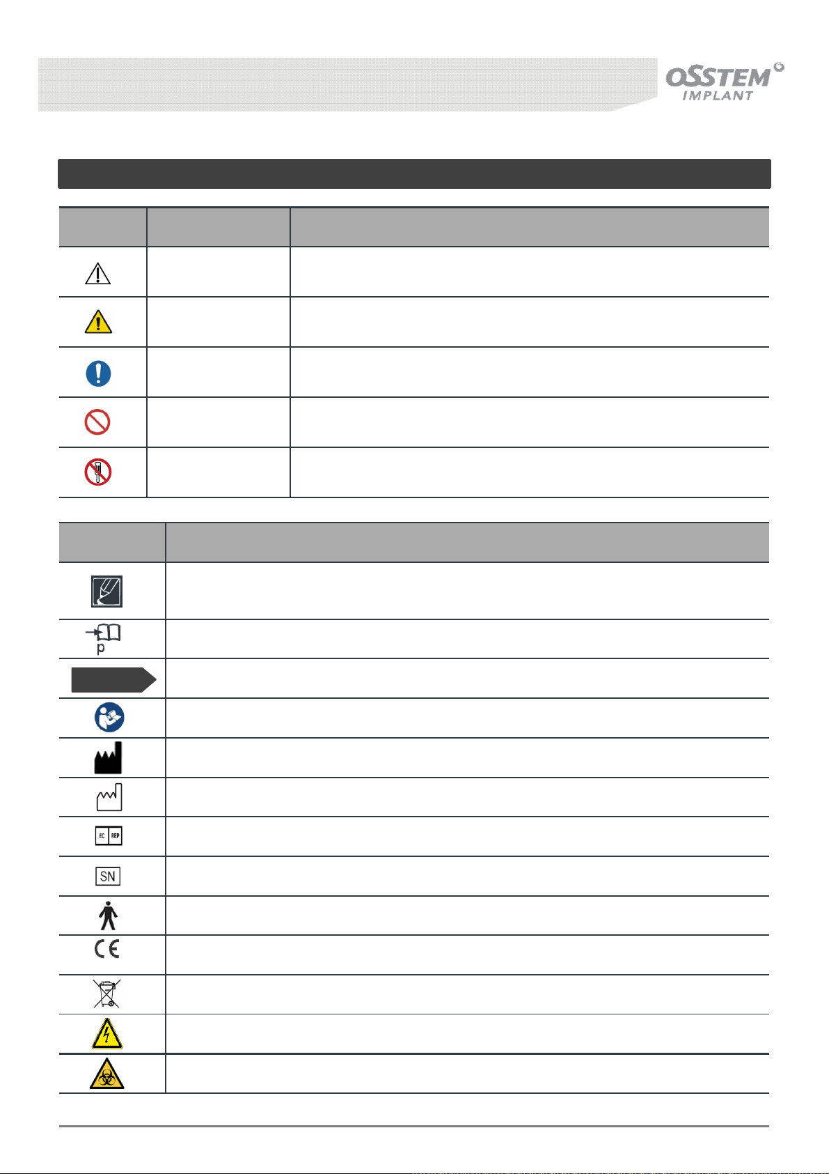
Used in cautionary matters for safety
Symbol Name Function
Caution
Warning
Mandatory action You must observe the following instructions.
Prohibition You should not do the following.
Disassembling
Prohibited
You may damage the equipment if you do not observe the following
instructions.
You may lose your life or sustain serious injury if you do not observe the
following instructions.
This is a sign of prohibition of disassembly.
Symbol Function
The instruction is a supplementary description or a reference regarding the movement
of equipment motion.
Refer to the relevant page
Before Use!
2460
Setting necessary before operating the product function.
Refer to instruction manual / booklet
Manufacturer
Date of manufacture
European Authorized Representative
Serial Number
Type B Applied Part
CE Marking of Conformity
Waste Electrical and Electronic Equipment symbol
Warning: Dangerous Voltage
Warning: Biological hazard
K3
UNIT CHAIR [OS-UM-C002 Ver.2]
2
Page 3
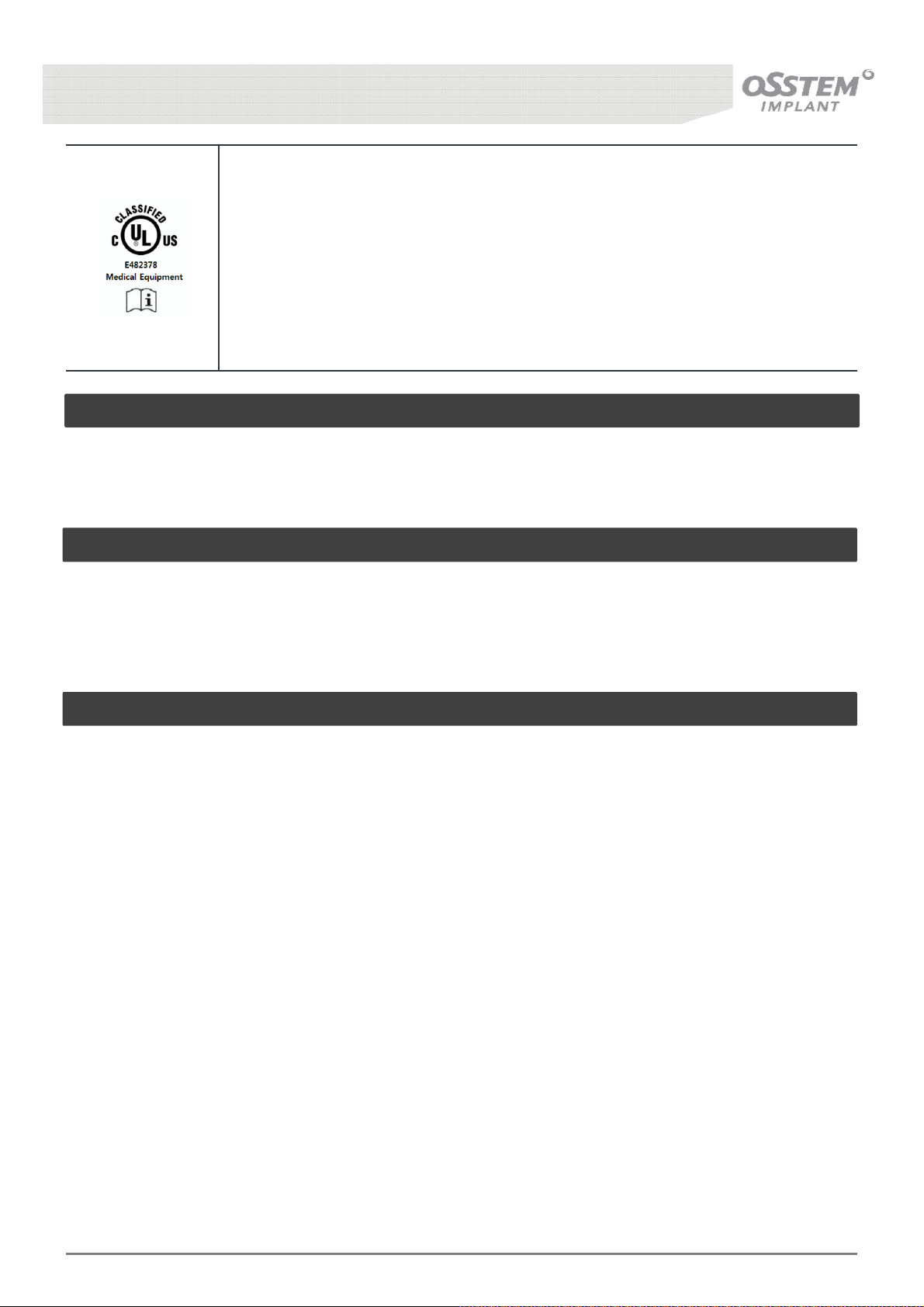
Medical Equipment,
(E482378)
WITH RESPECT TO ELECTRICAL SHOCK, FIRE AND MECHANICAL HAZARDS ONLY
IN ACCORDANCE WITH [STANDARD]
ANSI/AAMI ES60601-1 (2005) + AMD 1 (2012)
CAN/CSA C22.2 NO. 60601-1:14 (2014)
IEC 80601-2-60 (2012)
IEC 60601-1-6 (2010) + AMD 1 (2013)
Intended use
Intended for use on humans in the area of dentistry and may only be used by trained dental
professionals.
Frequently used functions
Supports the patient’s body during treatment and allows selection of the treatment position.
Provides convenience in using instruments (Hand-piece, Scaler, Suction, etc) during treatment.
This User Manual
This user manual is for the K3 Mount/K3 Cart model of Osstem Implant Co., Ltd. (hereinafter referred to
as Osstem) and issued on 2017. 08. 10
The pictures on this user manual are drawn for descriptions, which may be partially different from the
actual items.
Refer to “Caution and Notice signs” and “Matters to check before reporting on failure” at the back of
the user manual to recheck the failure of the product before requesting service.
Be sure to read “Matters requiring attention for safety” before using the product to ensure correct
product use.
The user shall assume responsibility for injury or product damage occurring due to failure to follow
this user manual.
The exterior design and the product size may be changed without prior notice to improve the product’s
performance.
K3
UNIT CHAIR [OS-UM-C002 Ver.2]
3
Page 4
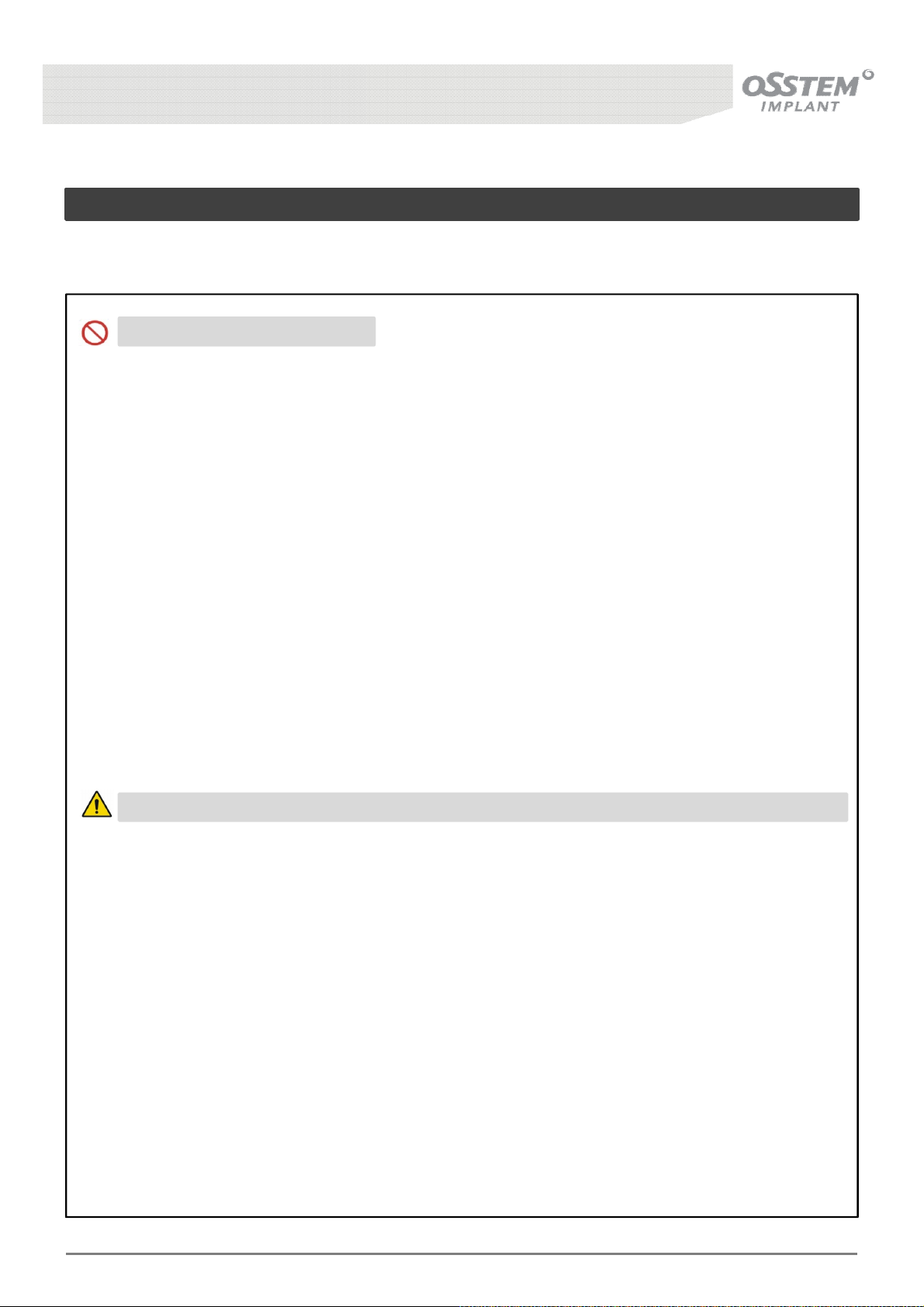
Matters requiring attention for safety
Related to installation
This Product should be installed by Osstem or an expert designated by Osstem, based on the installation
manual.
You should not do the following.
• Do NOT use this product in conditions other than the indicated power supply voltage [V~],
frequency [㎐] and acceptable current [A] (or power consumption) specifications.
- Have an exclusive power circuit ready for each machine; never share or divide the power with
that of another machine.
- Overheating and short-circuit may occur, which may cause accident or failure.
• Do NOT install the product in a place of high humidity or moisture, or where water splashes may
occur.
- Overheat and short-circuit may occur, which may cause accident or failure.
• Do NOT install the product in a place where chemicals are stored or where gas is generated.
- Electric shock or short circuit may occur, which may cause accident or failure.
• Do NOT put the product in a place where its power code, ground wire and wire for Foot Controller
may be damaged, such as places like door or passage.
- Electric shock or short circuit may occur, which may cause accident or failure.
• Do NOT use environmentally regulated substances.
• Do NOT use unpurified water for the chair.
You may lose your life or sustain serious injury if you do not observe the following instructions.
• Do NOT install the equipment in an unstable place with incline, vibration, or shock.
- Inappropriate installation may cause malfunction or failure.
• Do NOT use in a place negatively influenced by air pressure, temperature, humidity, ventilation,
sunlight, dust, and air containing salt.
- Inappropriate installation may cause malfunction or failure.
• Be sure to perform earthing for safety. Do NOT earth to gas pipes, plastic water pipes, or the
telephone line.
- This may cause electric shock, fire, failure, or explosion.
- Be sure to use ground plug socket.
- Be sure to perform earthing separately if the internal wiring of the ground terminal is not
connected, even if the plug socket has a ground terminal.
• Installation, modification, adjustment, exchange, maintenance, and repair of the product shall be
performed by an engineer who has been trained by Osstem or the employee of the official
distributors certified by Osstem.
K3
UNIT CHAIR [OS-UM-C002 Ver.2]
4
Page 5
Matters requiring attention for safety
Matters requiring attention regarding power supply
You may lose your life or sustain serious injury if you do not observe the following instructions.
• Wipe off foreign substances (dust, water) on the power plug terminal and contact part with dry
cloth regularly.
• Do NOT pull the power code (wire) from the power plug.
• Never bend, pull excessively, twist, or tie the power code. Never hang it on a metal part, put a
heavy object on it, insert it in between, or push it in behind the product.
• Connect the power plug to the tip of the plug socket firmly, do NOT use a damaged power plug,
or power code or loose plug socket.
• WARNING: To avoid the risk of electric shock, this equipment must only be connected to a supply
mains with protective earth.
You may damage the equipment if you do not observe the following instructions.
• Disconnect the power plug if you will not use it for a long time, or in case of thunder and
lightning.
- Failure to do so may cause electric shock or fire.
K3
UNIT CHAIR [OS-UM-C002 Ver.2]
5
Page 6
The K3 is suitable for use in all establishments other than
establishments
Matters requiring attention for safety
Matters requiring attention regarding the EMC
The equipment requires special prevention measures related to EMC, and should be installed and
operated in an environment that complies with the following EMC guide.
• Mobile RF communication device may disrupt the equipment.
• Using a cable other than one provided by Osstem may negatively affect EMC
performance.
• Do not use the equipment in the proximity of or mounted on another electronic device.
K3 is designed to be used in an electromagnetic emission environment designated in the table
below.
* Guidance and manufacturer’s declaration - Electromagnetic emission
• The K3is intended for use in the electromagnet environment specified below.
• The customer or the user of the K3 should assure that it is used in such an environment.
Emission
RF emission - CISPR11 Group 1
RF emission - CISPR11 Class A
Harmonic emission
IEC 61000-3-2
Voltage fluctuation / Flicker
emission IEC 61000-3-3
Compliance
Class A
Complies
Electromagnetic Environment - Guide
The K3uses RF energy only for its internal function. There
fore, its RF emissions are very low and are not likely to
cause any interference in nearby electronic equipment.
domestic, and may be caused in domestic
and those directly connected to the public low-voltage
power supply network that supplies buildings used for
domestic purposes, provided the following warning is
needed:
Warning: This equipment/system is intended for use by
healthcare professionals only. This equipment/ system
may cause radio interference or may disrupt the
K3
UNIT CHAIR [OS-UM-C002 Ver.2]
operation of nearby equipment. It may be necessary to
take mitigation measures, such as re-orienting or
relocating the K3 or shielding the location.
6
Page 7
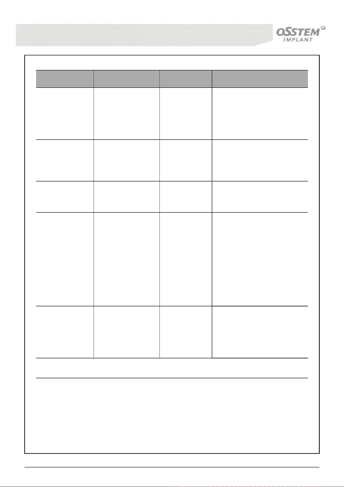
* Guidance and manufacturer’s declaration – Electromagnetic wave immunity
Immunity
Electrostatic
discharge(EDS)
IEC 61000-4-2
Electric transient /
Burst
IEC 61000-4-4
Surge
IEC 61000-4-5
Voltage dips, short
interruptions and
voltage variations
on power supply
input lines
IEC 61000-4-11
IEC 60601
Test level
± 6 kV Contact
± 8 kV Air
± 2 kV
(for power supply line)
± 1 kV
(for input/output line)
± 1 kV (line-line)
± 2 kV (line-earth)
<5 %
U
T
for 0,5 cycle
40 %
U
T
for 5, 6 cycles
70 %
U
T
for 25, 30 cycles
<5 %
U
for 5 s
T
Compliance
level
± 6 kV
± 8 kV
± 2 kV
± 1 kV
1 kV
± 2 kV
<5 %
U
T
for 0,5 cycle
40 %
U
T
for 5, 6 cycles
70 %
U
T
for 25, 30 cycles
<5 %
U
for 5 s
T
Electromagnetic Environment
- Guide
Floors should be wood, concrete
or ceramic tile. If floors are
covered with synthetic material,
the relative humidity should be at
least 30 %..
Mains power quality should be
that of a typical commercial or
hospital environment.
Mains power quality should be
that of a typical commercial or
hospital environment.
Mains power quality should be
that of a typical commercial or
hospital environment. If the user
of the K3 requires continued
operation during power mains
interruptions, it is recommended
that the K3 be powered from an
uninterruptible power supply or a
battery
Power frequency
(50/60Hz)
3 A/m 3 A/m
magnetic field
IEC 61000-4-8
Note: UTis the AC main power voltage prior to application of the test level.
K3
UNIT CHAIR [OS-UM-C002 Ver.2]
Power frequency magnetic fields
should be at levels characteristic
of a typical location in a typical
commercial or hospital
environment.
7
Page 8
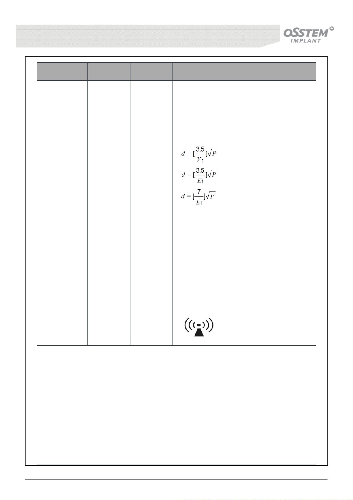
Immunity
Conductive RF
IEC 61000-4-6
IEC 60601
Test level
3 Vrms
150 kHz to
80 MHz
Compliance
level
3 Vrms
Electromagnetic Environment
- Guide
Portable and mobile RF communications
equipment should be used no closer to any part
of theK3 including cables, than the recommended
separation distance calculated from the equation
applicable to the frequency of the transmitter.
Recommended separation distance
80 MHz to 800MHz
800 MHz to 2,5GHz
where P is the maximum output power rating of
the transmitter in watts (W) according to the trans
mitter manufacturer and d is the recommended
separation distance in meters (m)
Field strengths from fixed RF transmitters, as
Radioactive RF
IEC 61000-4-3
3 V/m
80 MHz to
2,5 GHz
3 V/m
determined by an electromagnetic site survey,
a
should be less than the compliance level in each
frequency range.
b
Interference may occur in the vicinity of
Equipment marked with the following symbol:
Note 1 At 80 MHz and 800 MHz, the higher frequency range applies.
Note 2 These guidelines may not apply in all situations. Electromagnetic propagation is affected by
absorption and reflection from structures, objects and people
a
Field strengths from fixed transmitters, such as base stations for radio (cellular/cordless) telephon
es and land mobile radios, amateur radio, AM and FM radio broadcast and TV broadcast cannot be
predicted theoretically with accuracy. To access the electromagnetic environment due to fixed RF tr
ansmitters, an electromagnetic site survey should be considered. If the measured field strength in t
he location in which the K3 is used exceeds the applicable RF compliance level above, the K3 shoul
d be observed to verify normal operation. If abnormal performance is observed, additional measure
s may be necessary, such as re- orienting or relocating the K3.
b
Over the frequency range 150 kHz to 80 MHz, field strengths should be less than 3 V/m.
K3
UNIT CHAIR [OS-UM-C002 Ver.2]
8
Page 9
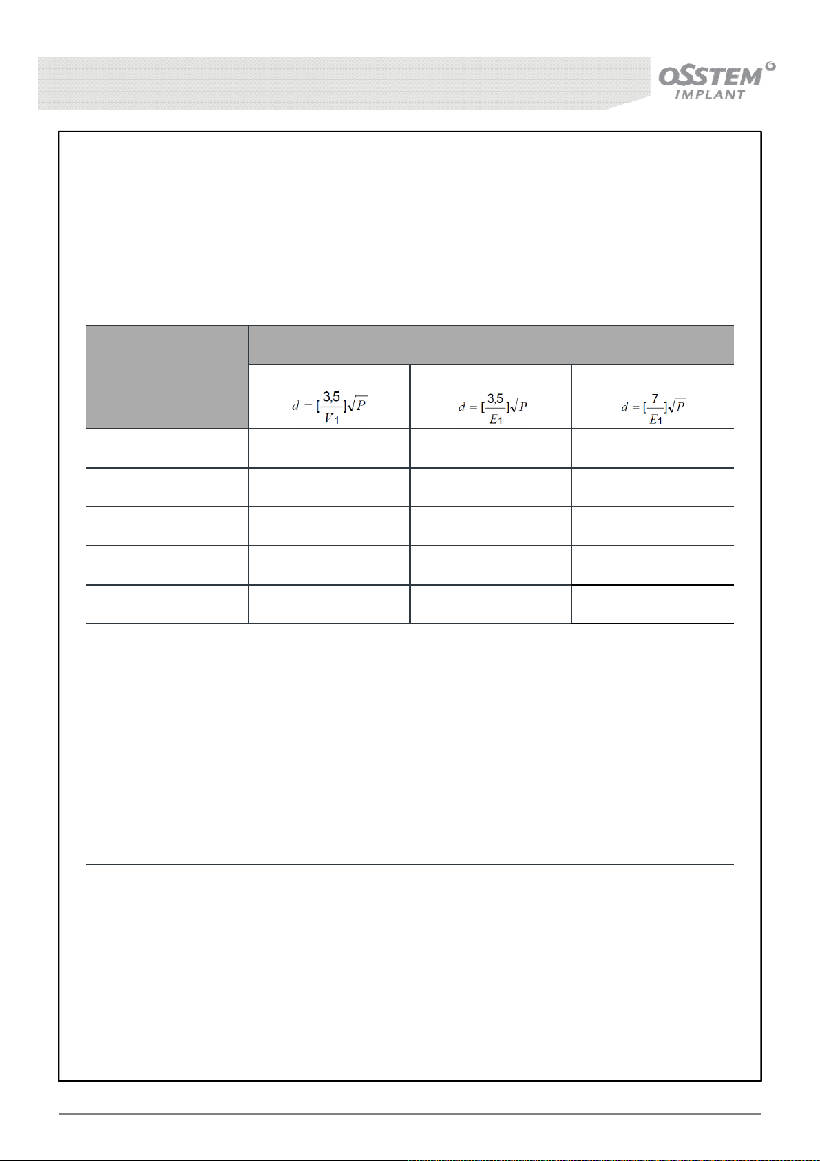
* Recommended separation distance between portable and mobile RF communication
equipment and the K3
• The K3is intended for use in an electromagnetic environment in which radiated RF disturbances are
controlled. The customer or the user of the K3can help prevent electromagnetic interference by
maintaining a minimum distance between portable and mobile RF communications equipment
(transmitters) and the K3as recommended below, according to the maximum output power of the
communications equipment.
Separation distance according to the transmitter frequency [M]
Maximum rated
output
150 kHz - 80 MHz
80 MHz - 800 MHz 800 MHz - 2,5 GHz
of transmitter [W]
0.01
0.1
1
10
100
For transmitters rated at a maximum output power not listed above, the recommended separation
distance d in meters (m) can be estimated using the equation applicable to the frequency of the tra
nsmitter, where P is the maximum output power rating of the transmitter in watts (W) according to
the transmitter manufacturer.
NOTE 1 At 80 MHz and 800 MHz, the separation distance for the higher frequency range applies.
NOTE 2 These guidelines may not apply in all situations. Electromagnetic propagation is affected by
absorption and reflection from structures, objects and people
0.12 0.12
0.38 0.38
1.2 1.2
3.8 3.8
12 12 23
0.23
0.73
2.3
7.3
K3
UNIT CHAIR [OS-UM-C002 Ver.2]
9
Page 10
Matters requiring attention for safety
Matters requiring attention regarding the operation of the equipment
You should not do the following.
• Do NOT put an object or your finger or foot in the part or range of operation of the body such as
under the Seat or Backrest joint.
- If caught while in operation, you may get injured or the equipment may get damaged or fail.
• Never apply excessive load to the Table Arm, Lamp Arm, put something heavy, or lean or sit on
the Seat and tips of the Backrest and Headrest or Table, Assistant Tray, and Mouse Tray.
- The reversion and damage of the equipment may cause injury or failure.
• This Product is only to be used in the field of dentistry. It is forbidden to use this product for
anything other than the field of dentistry.
You may damage the equipment if you do not observe the following instructions.
• While operating the equipment, observe the following and check if it is safe.
- Inappropriate operation may cause malfunction or failure.
• Do NOT install the equipment in an unsafe place with Incline, vibration, and shock.
- The equipment should not be operated by a person other than a qualified personnel in charge
- Do NOT take motion or position that may put the patient at risk.
- Do NOT put your finger, part of your body, or baggage in or around the moving part of the
main body.
- Do NOT allow more than two persons on the Seat.
(e.g. holding a child while undergoing treatment).
- Do NOT allow any person who is not involved in the treatment near the equipment.(infant, etc.)
- Do NOT do any risky act other than those mentioned above.
• If there is risk such as collision while operating the Seat of the main body, perform emergency
stop urgently as follows.
- Press one of the keys to operate the chair on the Doctor’s Side Table Control panel.
- Press one of the keys to operate the chair on the Assistant Side Table Control panel.
• WARNING: Do not modify this equipment without authorization of the manufacturer.
• The responsibility for use and maintenance lies with the user(hospital or clinic, etc.) and only
dentists and dental hygienists are recommended to use the product.
• Refilling or injecting distilled water over the scale marking the limit of the distilled water bottle
can cause damage to the product or the risk of electric shock and fire.
• Check the tube connection state of all instruments before using the device.
• Expel water from the device pipe for about 2 ~ 3 minutes every day before starting treatment.
• Supply spittoon with water a few times.
K3
UNIT CHAIR [OS-UM-C002 Ver.2]
10
Page 11
Matters requiring attention for safety
Matters requiring attention regarding the operation of the equipment
You must observe the following instructions.
• The waste generated from the product should be discarded or recycled to prevent environmental
pollution. Please comply with the pertinent country’s or local regulations for the details on waste.
• Please use the Clean Head System Hand-piece for infection prevention.
• The user must wear personal protective equipment to prevent the infection during dental
procedures.(e.g. gowns, lab coats, gloves, masks, and protective eyewear or face shields)
• Recommended that the K3 use in the combination with anti suction equipment and amalgam
separator device.
• Osstem does not provide the Hand-piece and the Scaler. And recommend that user contact us
before using the purchased Hand-piece and Scaler. Also, risk/side effects associated with the
purchased Hand-piece and Scaler is not responsible.
• The 3-Way syringe Nozzle provided by Osstem is not sterilized.
Before using for the first time, Do sterile to the according below.
- Sterilization type : Gravity
- Exposure time : 132˚C, 7min
- Dry time : 15min
K3
UNIT CHAIR [OS-UM-C002 Ver.2]
11
Page 12
Matters requiring attention for safety
On matters requiring attention regarding the operation of the equipment
You may damage the equipment if you do not observe the following instructions.
• The patient and operator may be injured or harmed by the operation of the examining table.
- Both patient and operator should take caution while the examining table is operating.
- Avoid acts like getting on and jump down the examining table.
- Do NOT place your finger, part of your body or baggage on the moving part of the main body
or around it.
- No more than one patient should be on the Seat.
• Adding excessive load to the moving Arm may cause risk or injury on the patient or user.
- Do not add excessive load to the Table Arm.
- Do not add load heavier than 50N (5kgf) on the Doctor’s Side Table.
• Connecting inappropriate medical system equipment to the medical device may cause electric
shock.
- To connect an IT device to the medical device, follow the regulations of EN 60601-1.
• Do NOT attach sticker or adhesive tape to the Instrument Tube.
- The instrument Tube may be torn.
- Discharge water in the pipe of the medical device for about two minutes before treatment each
day.
- Cleanse the water and air pipes or discharge water or air before and after using the equipment
during weekends or holidays when you will not use it.
- Sterilize thoroughly.
- Supply water to the spittoon a few times.
• Occurrence of bedsores
- Pay attention to the occurrence of bedsores in case of long treatment.
• To change all instrument tips or bars, be sure to do so when they are stopped.
- Replacement during operation may cause unexpected accident and risk.
- Using an uncertified product may cause unexpected accident and risk.
- When putting each instrument into the holder, do so slowly and surely.
• Do NOT apply heavy shock or load to the Water Supply Device. Likewise, never operate or
disassemble it by force.
• This product meets the application requirements(EN60601-1-2) of the electromagnetic field.
- Try not to use cell phones in hospital or dental offices.
- Turn off electric equipment such as computer storage media or portable hearing aids during
treatment.
- When high frequency electronic equipment is used, make sure to turn off the main power of
the dental unit chairs. Otherwise unexpected accidents or failures of the product may occur
due to malfunction.
You may lose your life or sustain serious injury if you do not observe the following instructions.
• When reaching your hand toward the Table or Instrument, your hand or sleeve may get caught in
the instrument housed on the holder, which may lead to injury or infection.
• Take special caution of instrument installed in the holder when reaching your hand toward the
Table or Instrument.
• To disassemble it for sterilization, or repair, be sure to turn the Main Power OFF; disassemble
only after the equipment has sufficiently cooled down.
K3
UNIT CHAIR [OS-UM-C002 Ver.2]
12
Page 13

Contents
1. Product Description…………………………………………………………………...……...
1-1. Appearance………………………………………………………….………………………………..…………………….
1-2. Description of the exterior………………………………………….………………………………………..…….
2. Putting the system into operation………………………………..…………….……....
2-1. Socket Outlet……………………………………………………………………………………………..…….………...
2-2. Main Switch………………………………………………………………………………………………..………………
3. Patient Chair………………………………………………………………………….………....
3-1. Adjusting the Patient Position….……………………………………………………………….……………....
3-2. Adjusting the Armrest……………………………………………………………………………….…………….....
3-3. Adjusting the Headrest..…………………………………………………………………………………………….
3-4. Emergency Stop.……………………………………………………………………………………………………..….
3-5. Chair Software-Basic Settings..……………………………………………………………………………..……
3-6. Chair Software-Changing the Settings………………………………………………………………………
4. Patient Chair - Option…………………………….…………………………………..……..
4-1. 2-Link Headrest…………………………………………………………………………………………………………..
5. Doctor’s Interface…………………………………………………………………….………..
5-1. Doctor’s Table Panel…………………………………………………………………………………………………..
5-2. Positioning the Doctor’s Table…………………..……………………………………………………………...
5-3. Instrument……………………………………………………………………………………………………………..……
5-4. High Speed Hand-piece……………………………………………………………………………………………..
5-5. Low Speed Hand-piece…………………………………………………………………………………………......
5-6. 3-Way Syringe……..…………………………………………………………………………………………………..…
5-7. Foot Controller……………………………………………………………………………………………………..…….
15
15
17
21
21
23
24
24
27
28
29
31
34
36
36
37
37
41
42
44
46
47
49
6. Doctor’s Interface - Option………………………………………………………….…….
6-1. Scaler……………………………………………………………………………………………………….……………..…..
6-2. Foot Controller-Option………………………………………………………………………...………………......
6-3. Other Options…………………………………………………………………………………………………………….
7. Assistant’s Interface……………………………………………………………………..…...
7-1. Assistant Table Panel………………………………………………………………………………………………...
7-2. Saliva Ejector..……………………………………………………………………………………………………….…...
7-3. Assistant Table Holder……………………………………………………………………………………………....
8. Assistant’s Interface - Option……………………………………………………………..
8-1. Assistant Table Holder-Option.………………………………………………………………………………....
9. Water Dispensing System………………..………………………………………………...
9-1. Water Dispensing System…………………………………………………………………………………………..
10. Water System - Option……………………………………………………………..……..
10-1. Bottled Water System..…………………………………………………………………………………………....
10-2. Waterline Cleaning System.……………………………………………………………………………..………
10-3. Other Options…………………………………………………………………………………………………………..
K3
UNIT CHAIR [OS-UM-C002 Ver.2]
50
50
52
53
54
54
55
56
57
57
59
59
62
62
64
65
13
Page 14

11. Dental Light - Option……………………………………………………………...…….…..
11-1. Dental Light……………………………………………………….………………………………..………..……………
67
67
12. Other Accessories - Option…………………………………………..………..……........
12-1. Monitor Arm..…………………………………………………………………………………………..……………......
12-2. HANARO Console..…………………………………………………………………………………..……..…………
13. Cleaning and Maintenance…………………………………………………………....…..
13-1. Barrier Protection..…………………………………………………………………………………………………..…
13-2. Upholstery…………………………………………………………………………………………………………..…......
13-3. Cleaning the Unit………………………………………………………………………………………………..….....
13-4. Cleaning the 3-Way Syringe………………………………………………………………………………..……
13-5. Saliva Ejector...…………………………………………………………………………………………………..……….
13-6. Water System Cleaning and Maintenance .………………………………………………………..……
14. Cleaning and Maintenance - Option……….……………………………….…….…...
14-1. Cleaning the Spittoon Valve..……………………………………………………………………………..…….
14-2. Water System Cleaning and Maintenance .………………………………………………………..……
15. How to store and maintain after use..……………………………………….……….
16. Troubleshooting…….…………………………………………………………….…………..
17. Product Specifications………….………………………………………………………......
17-1. Product Specifications.…………………………………………………………………………………………..….
17-2. Chair of Human Body Mass Distribution ………………………………………………..….…………..
17-3. Information on the packaging: Storage and transportation…….……………….…..………..
70
70
72
73
73
73
74
75
76
77
78
78
79
83
84
85
85
88
89
18. Product Indications…..……………………………………………………………….….….
19. Warranty…………………………………………………………………………………………
20. Contact Information………………………………………………………………….……...
90
91
92
K3
UNIT CHAIR [OS-UM-C002 Ver.2]
14
Page 15
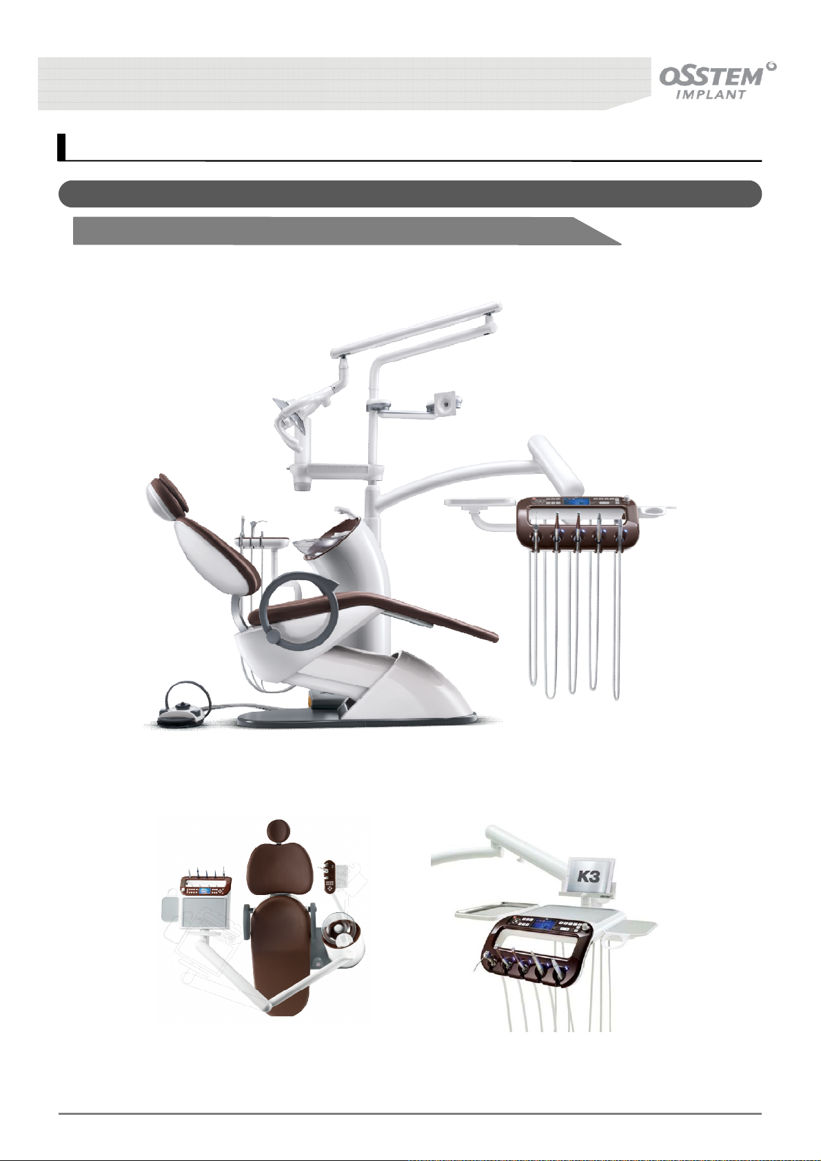
1. Product Description
1-1. Appearance
1-1-1. Mount Type
K3
UNIT CHAIR [OS-UM-C002 Ver.2]
15
Page 16
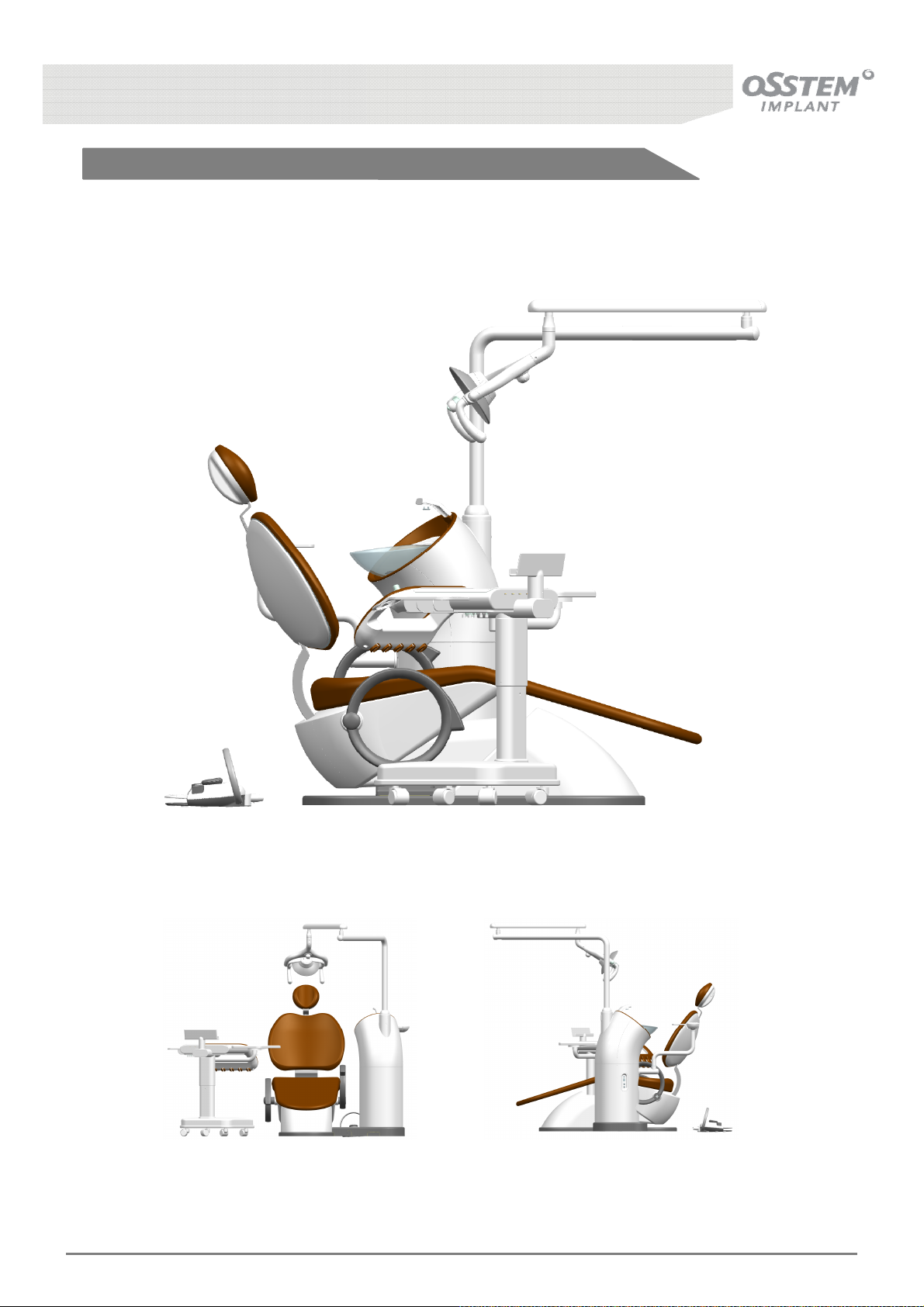
1-1-2. Cart Type
K3
UNIT CHAIR [OS-UM-C002 Ver.2]
16
Page 17
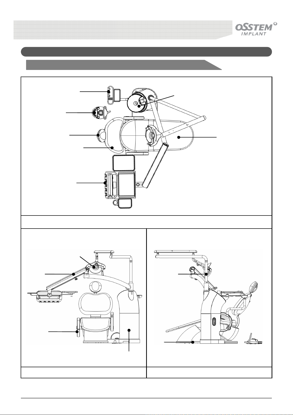
1-2. Description of the exterior
1-2-1. Mount Type
①
⑪
②
⑥
⑦
⑤
⑫
Top
⑩
④
③
⑬
Front Side
▶ Applied Part : Head Rest/Back Rest/Seat/Arm Rest/3-Way Syringe/Saliva Ejector(large, small)
⑨
⑧
K3
UNIT CHAIR [OS-UM-C002 Ver.2]
17
Page 18

① Foot Control: Device with which the doctor moves the Patient Chair up and down, and controls
devices such as the Hand-piece, using the foot.
② Doctor’s Table: Table installed with various devices necessary for treatment; consists of various
switches for operating instruments and the Treatment Chair.
③ Armrest: Device that relaxes the patient during treatment, renders a sense of safety to the movement
of the treatment device, and fixes the patient’s arms.
④ Table Balance Arm: Device that supports the Doctor’s Table including the Control Panel and allows
free Up/Down, Left/Right movement.
⑤ Seat: Device that supports the patient’s body during treatment and allows selection of the patient’s
treatment position.
⑥ Assistant Table: Table where the 3-Way Syringe and Saliva Ejector can be hung during treatment, and
the Unit & Treatment Chair can be controlled using the switches on the panel.
⑦ Spittoon: Location where the patient rinses his/her oral cavity and spits out saliva after treatment.
⑧ Base: Basic structure that supports the Patient Chair.
⑨ Light Pole: Device that supports the Dental Light, necessary for patient treatment, and allows free
UP/DOWN and LEFT/RIGHT movement of the Dental Light.
⑩ Dental Light : Device that emits light to enable detailed inspection of the patient’s oral cavity and
teeth during treatment.
⑪ Headrest: Rest that supports the head of the patient during treatment.
⑫ Backrest: Rest that supports the upper body of the patient during treatment, whose angle can be
adjusted according to the treatment position.
⑬ Unit Body: Stores constituting devices of the Unit Treatment Device, and acts as support for the
Spittoon.
K3
UNIT CHAIR [OS-UM-C002 Ver.2]
18
Page 19
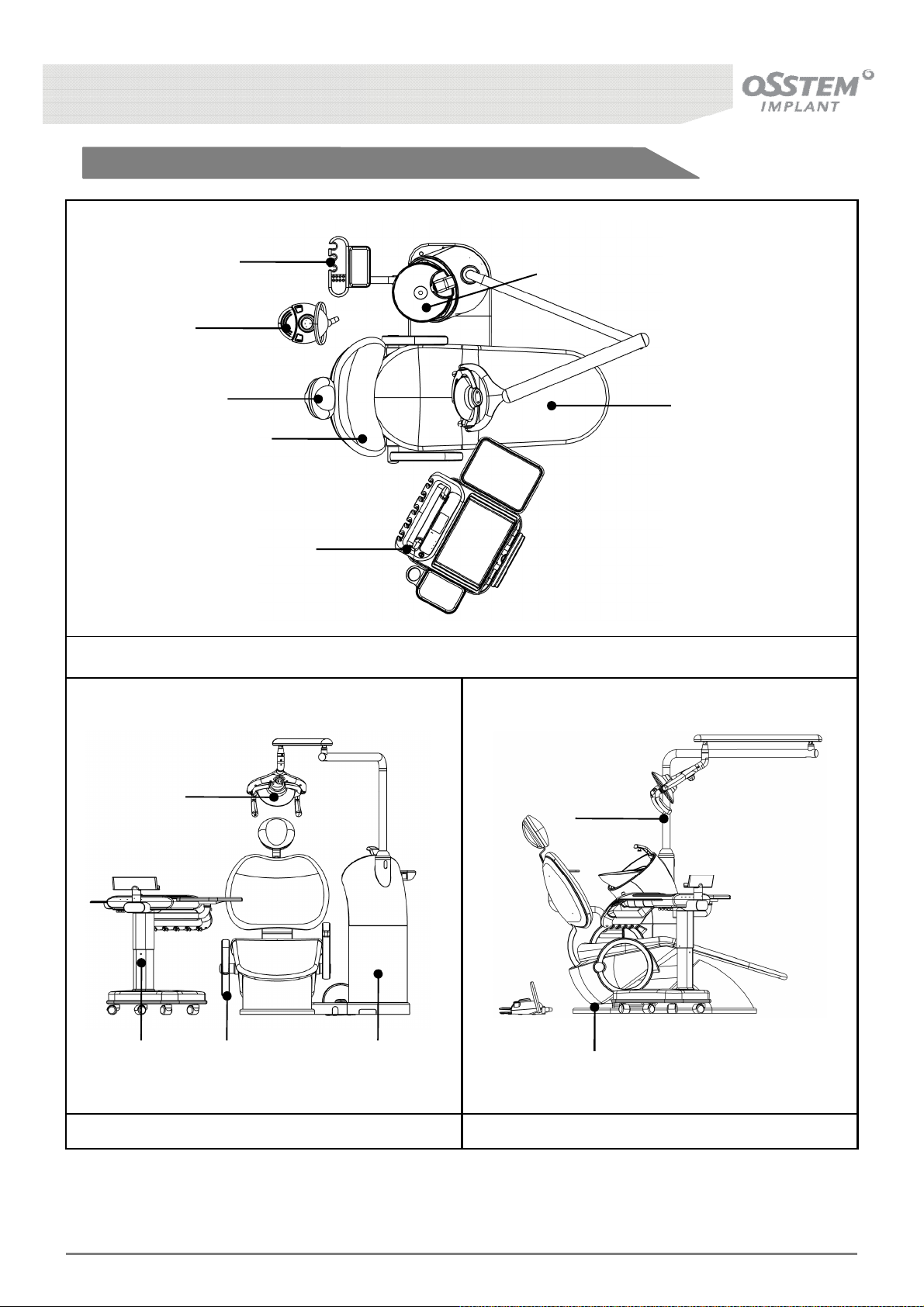
1-2-2. Cart Type
①
⑪
⑥
⑦
⑤
⑫
②
Top
⑩
⑨
④
▶ Applied Part : Head Rest/Back Rest/Seat/Arm Rest/3-Way Syringe/Saliva Ejector(large, small)
K3
UNIT CHAIR [OS-UM-C002 Ver.2]
③
Front Side
⑬
⑧
19
Page 20

① Foot Control: Device with which the doctor moves the Patient Chair up and down, and controls
devices such as the Hand-piece, using the foot.
② Doctor’s Table: Table installed with various devices necessary for treatment; consists of various
switches for operating instruments and the Treatment Chair.
③ Armrest: Device that relaxes the patient during treatment, renders a sense of safety to the movement
of the treatment device, and fixes the patient’s arms.
④ Table Balance Arm: Device that supports the Doctor’s Table including the Control Panel and allows
free Up/Down, Left/Right movement.
⑤ Seat: Device that supports the patient’s body during treatment and allows selection of the patient’s
treatment position.
⑥ Assistant Table: Table where the 3-Way Syringe and Saliva Ejector can be hung during treatment, and
the Unit & Treatment Chair can be controlled using the switches on the panel.
⑦ Spittoon: Location where the patient rinses his/her oral cavity and spits out saliva after treatment.
⑧ Base: Basic structure that supports the Patient Chair.
⑨ Light Pole: Device that supports the Dental Light, necessary for patient treatment, and allows free
UP/DOWN and LEFT/RIGHT movement of the Dental Light.
⑩ Dental Light : Device that emits light to enable detailed inspection of the patient’s oral cavity and
teeth during treatment.
⑪ Headrest: Rest that supports the head of the patient during treatment.
⑫ Backrest: Rest that supports the upper body of the patient during treatment, whose angle can be
adjusted according to the treatment position.
⑬ Unit Body: Stores constituting devices of the Unit Treatment Device, and acts as support for the
Spittoon.
K3
UNIT CHAIR [OS-UM-C002 Ver.2]
20
Page 21
2. Putting the System into Operation
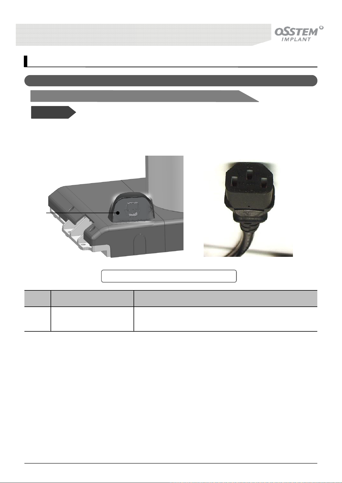
2-1. Socket Outlet
2-1-1. Basic Type
Before Use!
• Be sure to check the power source used in the equipment. (100-120/220-240V~)
• Connect the equipment’s power cord to the electrical outlet.
①
[Fig. 1] Positions of the Chair Main Plug Socket
NO. Name Function and operation method
① EMI/EMC FILTER
Reduce the transfer of electromagnetic noise between the drive
and mains power supply.
K3
UNIT CHAIR [OS-UM-C002 Ver.2]
21
Page 22
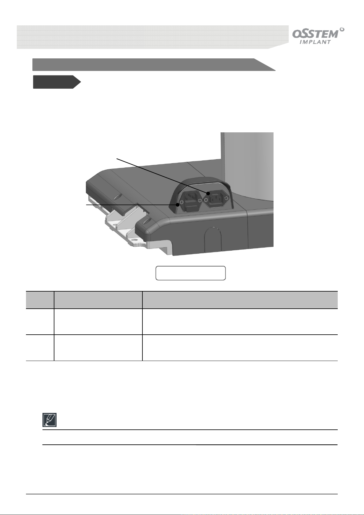
2-1-2. Option Type
Before Use!
• Be sure to check the power source used in the equipment. (100-120/220-240V~)
• Connect the equipment’s power cord to the electrical outlet.
②
①
[Fig. 2] Socket Outlet
NO. Name Function and operation method
① EMI/EMC FILTER
② IEC OUTLET
Reduce the transfer of electromagnetic noise between the drive
and mains power supply.
Interconnection couplers for connecting power supply cords to
electrical appliances up to 250 volts.
Reference
The power cable for connection with the IEC Outlet (②) is not provided.
K3
UNIT CHAIR [OS-UM-C002 Ver.2]
22
Page 23
2-2. Main Switch
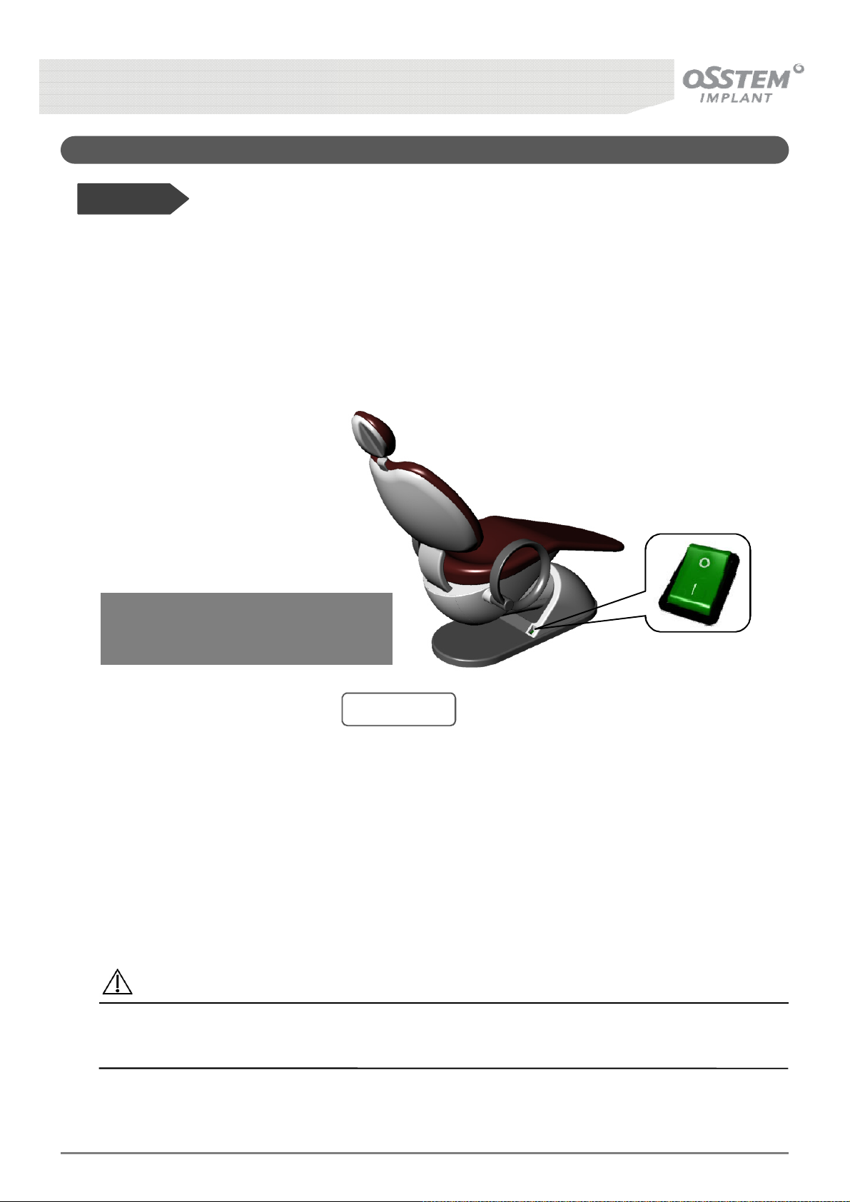
Before Use!
• Be sure to check the power source used in the equipment. (100-120/220-240V~)
• Connect the equipment’s power cord to the electrical outlet.
• Do not touch the power plug with wet hands.
■ How to switch on
Turn the main switch ON
The Main Switch turns green if you turn
on power and the Doctor’s Table Panel
LCD Display flickers once.
l [ON] status of power supply
O [OFF] status of power supply
[Fig. 3] Switch
Caution
Be sure to turn OFF the Main Switch when you finish treatment or if you will no longer use the
equipment.
K3
UNIT CHAIR [OS-UM-C002 Ver.2]
23
Page 24
3. Patient Chair
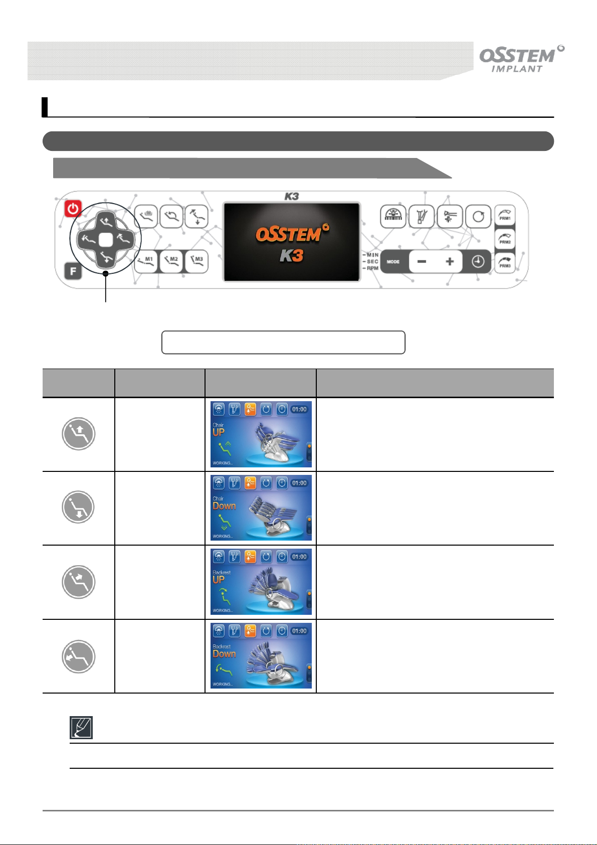
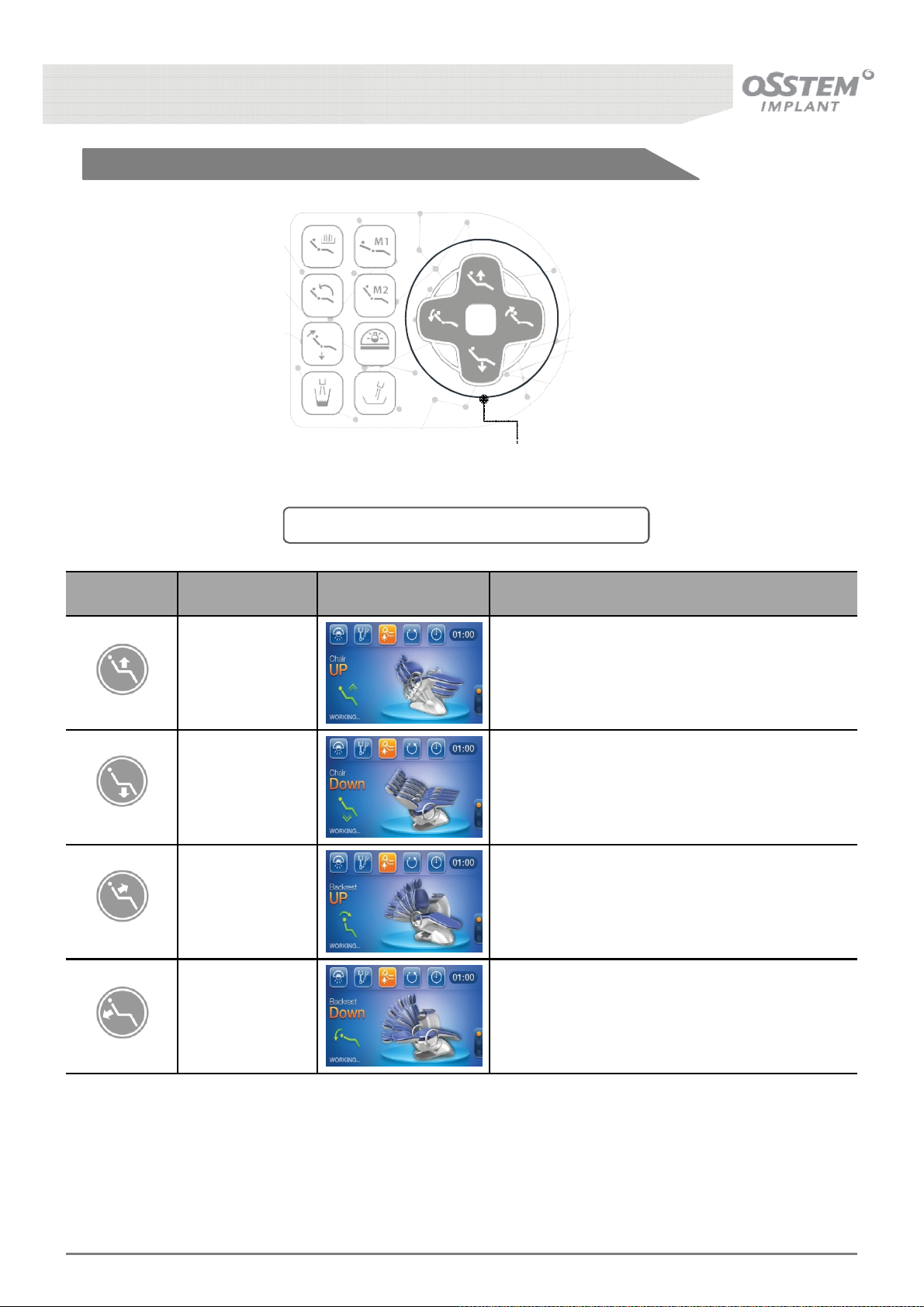
3-1. Adjust the Patient Position
3-1-1. Adjustment by the Doctor
Patient Chair
Positioning Button
[Fig. 4] Composition of the Doctor’s Table Panel
Button Function LCD Screen Description
Seat moves
upward
Seat moves
downward
Backrest moves
upward
Backrest moves
downward
Seat moves upward while the button is pressed.
Seat moves downward while the button is
pressed.
Backrest moves upward while the button is
pressed.
Backrest moves downward while the button is
pressed.
Reference
The Patient Chair moves only whilst one of the position adjustment buttons are being pressed.
K3
UNIT CHAIR [OS-UM-C002 Ver.2]
24
Page 25
3-1-2. Adjustment by the Assistant
Patient Chair
Positioning Button
[Fig. 5] Composition of the Assistant Table Panel
Button Function LCD Screen Description
Seat moves
upward
Seat moves
downward
Backrest moves
upward
Backrest moves
downward
Seat moves upward while the button is pressed.
Seat moves downward while the button is
pressed.
Backrest moves upward while the button is
pressed.
Backrest moves downward while the button is
pressed.
K3
UNIT CHAIR [OS-UM-C002 Ver.2]
25
Page 26
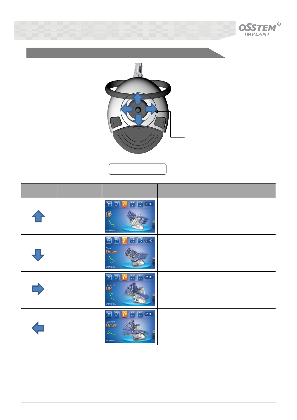
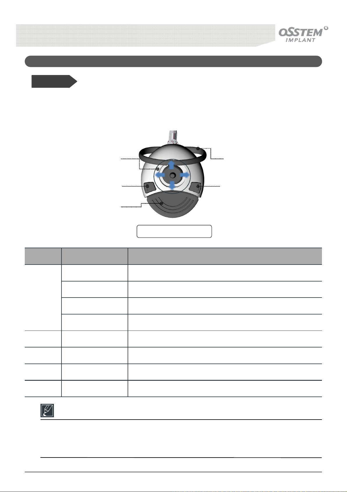
3-1-3. Adjustment using the Foot Controller
Buttons for adjusting
treatment position
[Fig. 6] Foot Controller
Direction Function LCD Screen Description
Seat moves
upward
Seat moves
downward
Backrest moves
upward
Backrest moves
downward
Seat moves upward while the joystick is pushed
in the indicated direction.
Seat moves downward while the joystick is
pushed in the indicated direction.
Backrest moves upward while the joystick is
pushed in the indicated direction.
Backrest moves downward while the joystick is
pushed in the indicated direction.
K3
UNIT CHAIR [OS-UM-C002 Ver.2]
26
Page 27
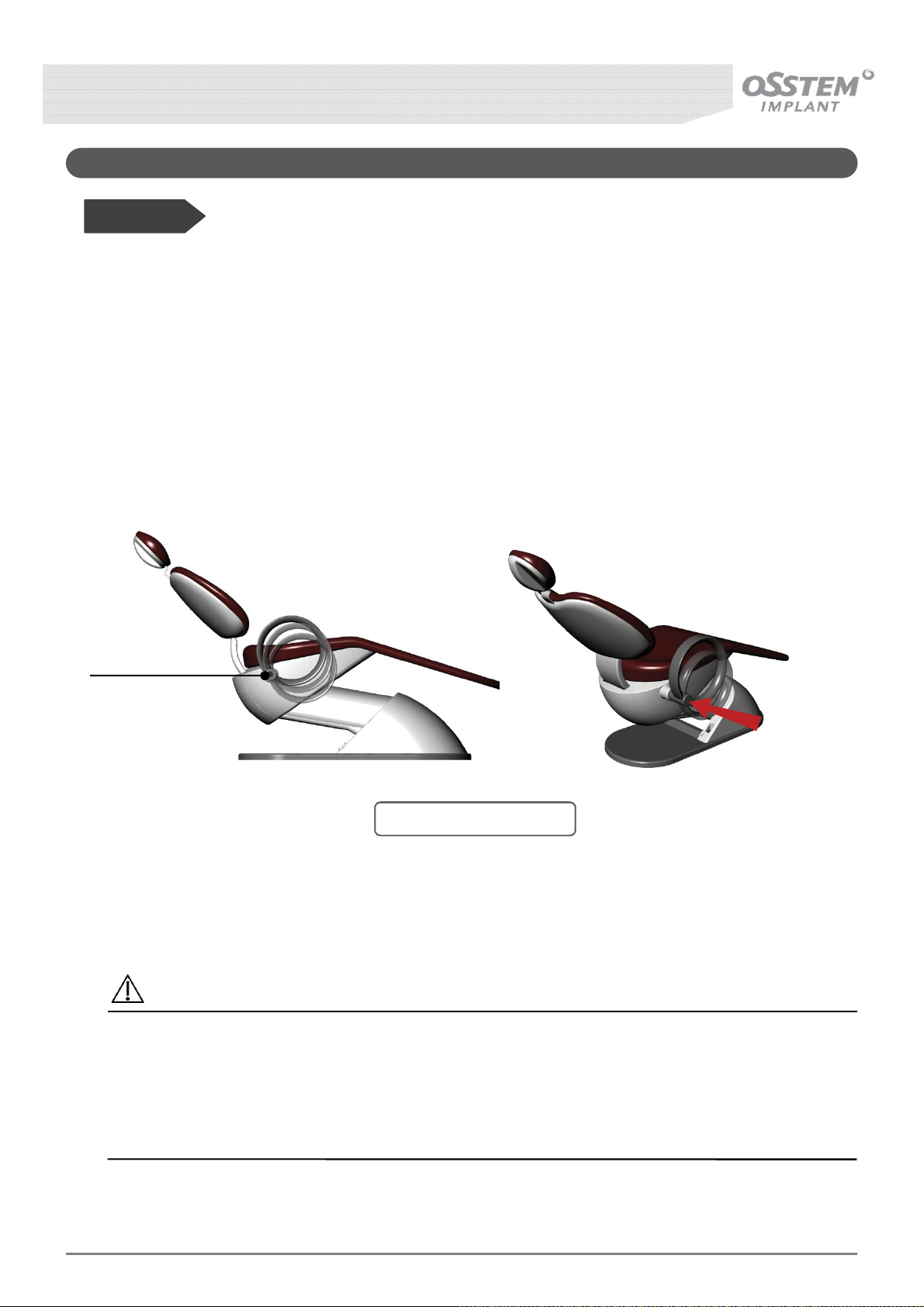
3-2. Adjusting the Armrest
Take care to ensure that the patient doesn’t trip over the Armrest whilst getting on and off the
Before Use!
• Only the Armrest on the right-hand side is capable of the function described below.
• The Armrest can be rotated 60º downward to minimise discomfort of the patient in getting on and
off the chair.
■ Method of Operation
When the Operation Button is pressed the Armrest automatically rotates downward; once the patient is
seated it can simply be pulled back into position.
Operation Button
[Fig. 7] Armrest Function
Caution
Excessive loading of the Armrest can adversely affect other equipments such as the Patient Chair
and the Unit, and may cause injury to persons nearby.
- Do not sit on or climb onto the Armrest
PUSH
-
chair.
K3
UNIT CHAIR [OS-UM-C002 Ver.2]
27
Page 28
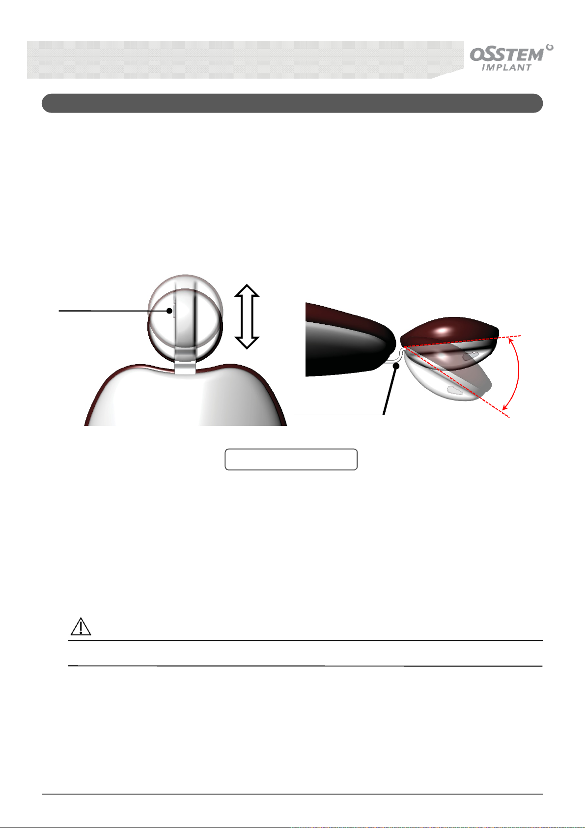
3-3. Adjusting the Headrest
■ Method of Operation
The Headrest can be adjusted according to each patient, as shown in
be rotated by pressing the operation button, moving to the desired angle, then releasing the button;
the angle is fixed once the button is released. Additionally, the entire Headrest can be moved up and
down by pulling and pushing, to accommodate patients of various upper body sizes.
UP
Operation Button
DOWN
Headrest Slide Bar
Fig. 8
below. The headrest can
ROTATE
[Fig. 8] Headrest Function
Caution
Placing heavy weights on the Headrest can lead to damage of the product.
K3
UNIT CHAIR [OS-UM-C002 Ver.2]
28
Page 29
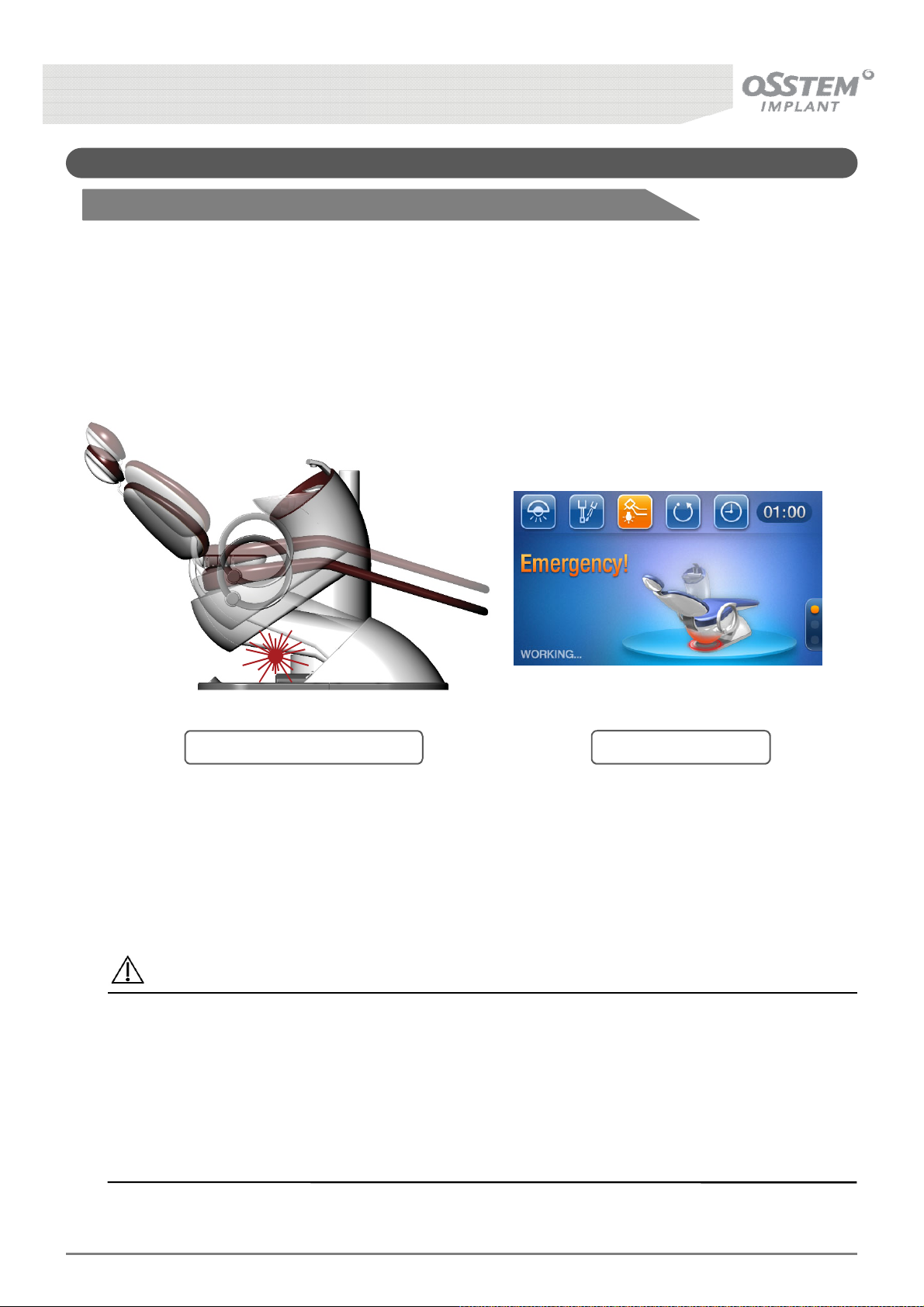
3-4. Emergency Stop
3-4-1. Safety Switch
■ How it works
It is an automatic system to protect the patient, dentist and system in case of an emergency. When an
object touches the safety switch installed in the channel, the operation of the chair is immediately
halted and the seat moves upward.
[Fig. 9] Safety Switch Position [Fig. 10] LCD Display
Caution
Safety Switch Precautions
- Ensure that no object, pet, patient or user is advertently or inadvertently located in the
operational area of the safety switch.
- Do not operate or modify the safety switch without prior consultation.
- If the safety switch does not operate due to causes including damage and irreversible
deformation, request maintenance service.
K3
UNIT CHAIR [OS-UM-C002 Ver.2]
29
Page 30
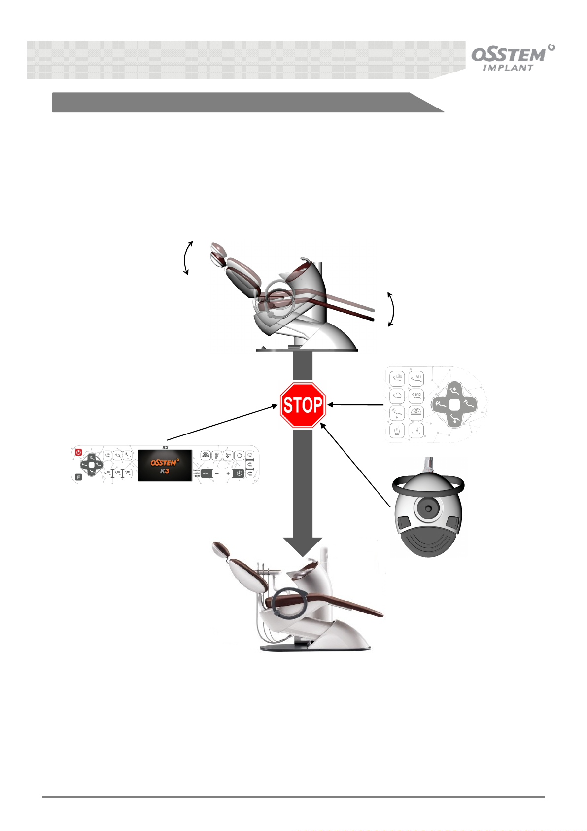
3-4-2. Emergency Stop Button
■ Method of Operation
Should an emergency situation arise during operation of the Chair, pressing the Emergency Stop
button on the Doctor’s Table Panel, Assistant’s Panel or Foot Controller immediately stops the Chair.
K3
UNIT CHAIR [OS-UM-C002 Ver.2]
30
Page 31
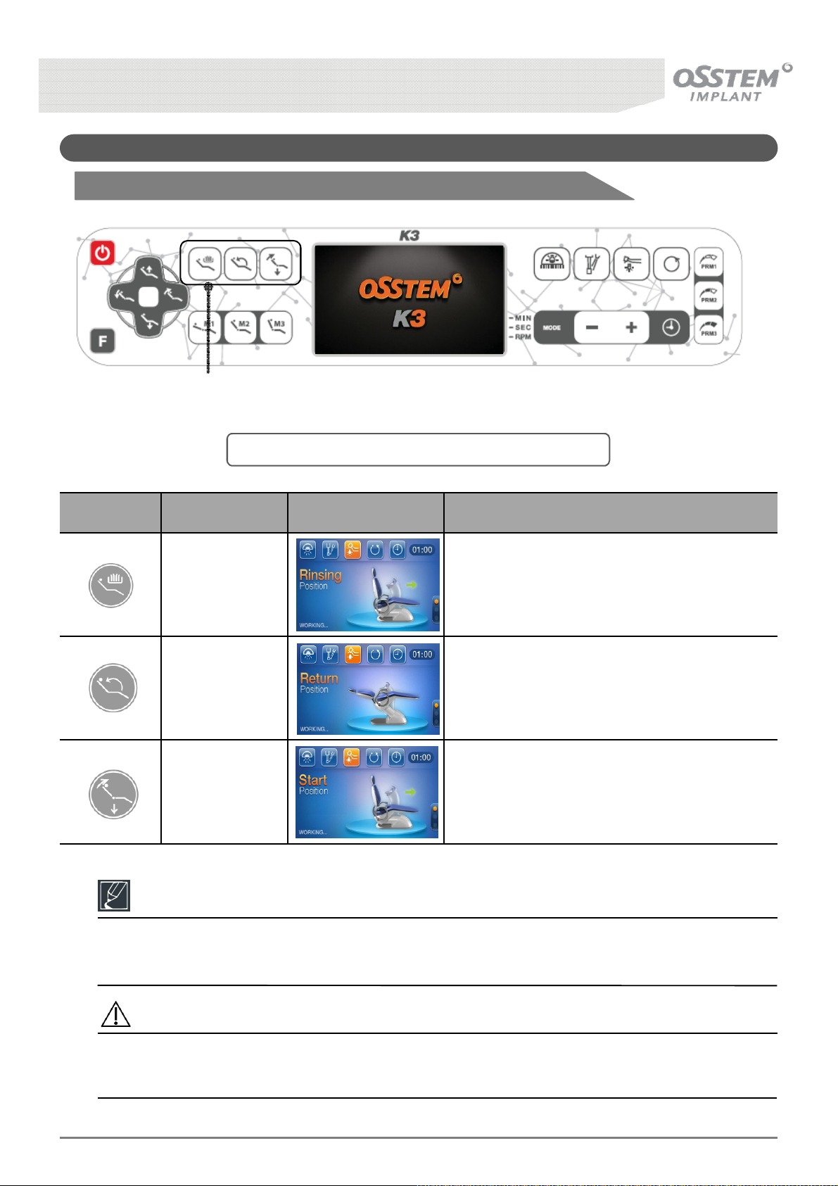
3-5. Chair Software-Basic Settings
3-5-1. Doctor's Table Panel Chair Software
Chair Positionng Memory
Button
[Fig. 11] Composition of the Doctor’s Side Table Panel
Button Function LCD Screen Description
Rinsing Position
Return Position
Start Position
Moves to the spittoon location for the patient
to rinse his/her oral cavity post-treatment.
Moves to the previous treatment position after
the patient has rinsed his/her oral cavity.
Moves to the original (lowest) position to make
it easier for the patient to climb off the chair.
Reference
The Chair Positioning Memory Button only needs to be pressed once to position the Chair
accordingly.
Caution
There must be no objects nearby when operating the Chair and the Backrest, and the Stool and
Armrest must not interfere with the Chair’s movements.
K3
UNIT CHAIR [OS-UM-C002 Ver.2]
31
Page 32
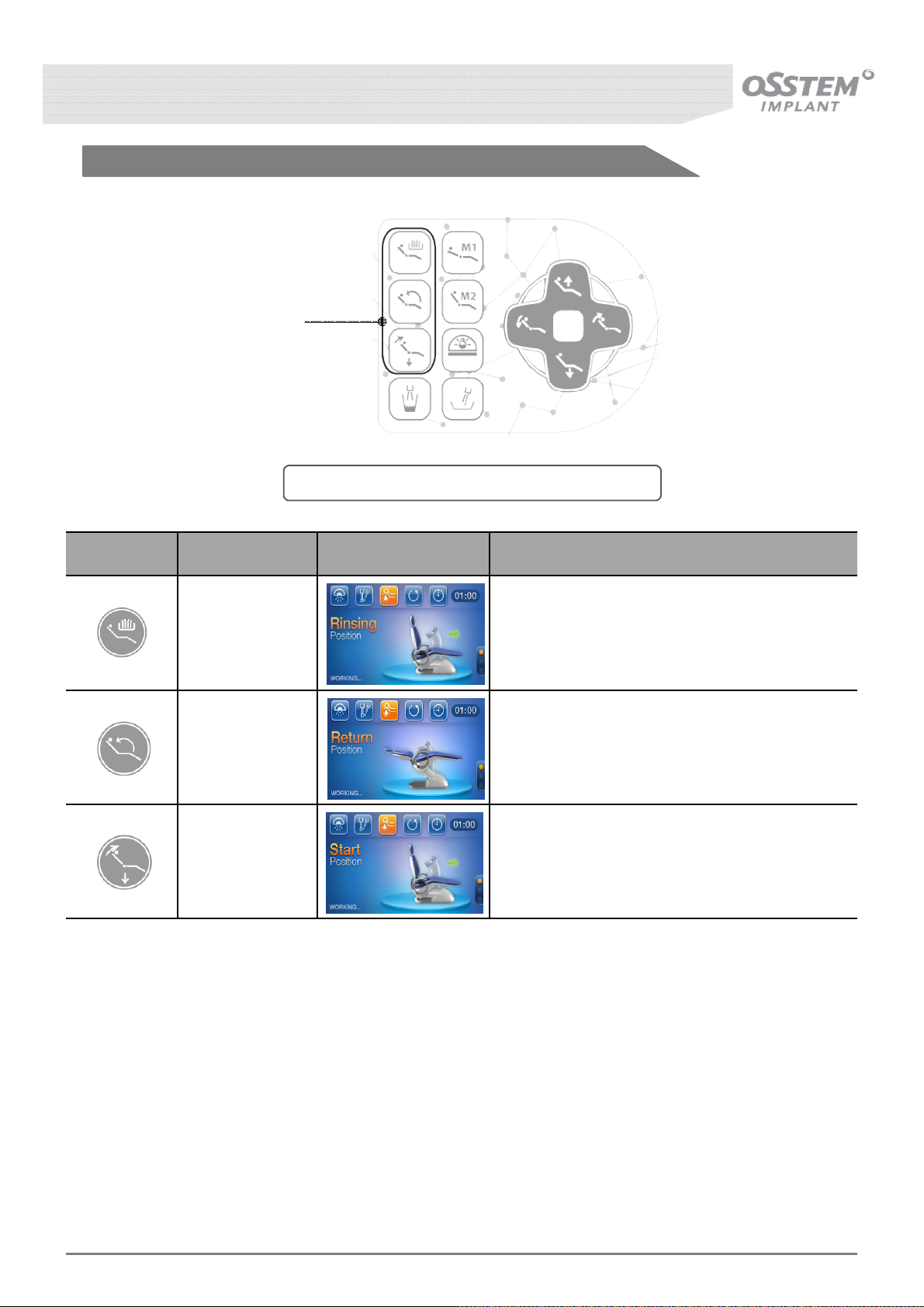
3-5-2. Assistant’s Panel Chair Software
Chair Positionng Memory
Button
[Fig. 12] Composition of the Assistant Table Panel
Button Function LCD Screen Description
Rinsing Position
Return Position
Start Position
Moves to the spittoon location for the patient
to rinse his/her oral cavity post-treatment.
Moves to the previous treatment position after
the patient has rinsed his/her oral cavity.
Moves to the original (lowest) position to make
it easier for the patient to climb off the chair.
K3
UNIT CHAIR [OS-UM-C002 Ver.2]
32
Page 33
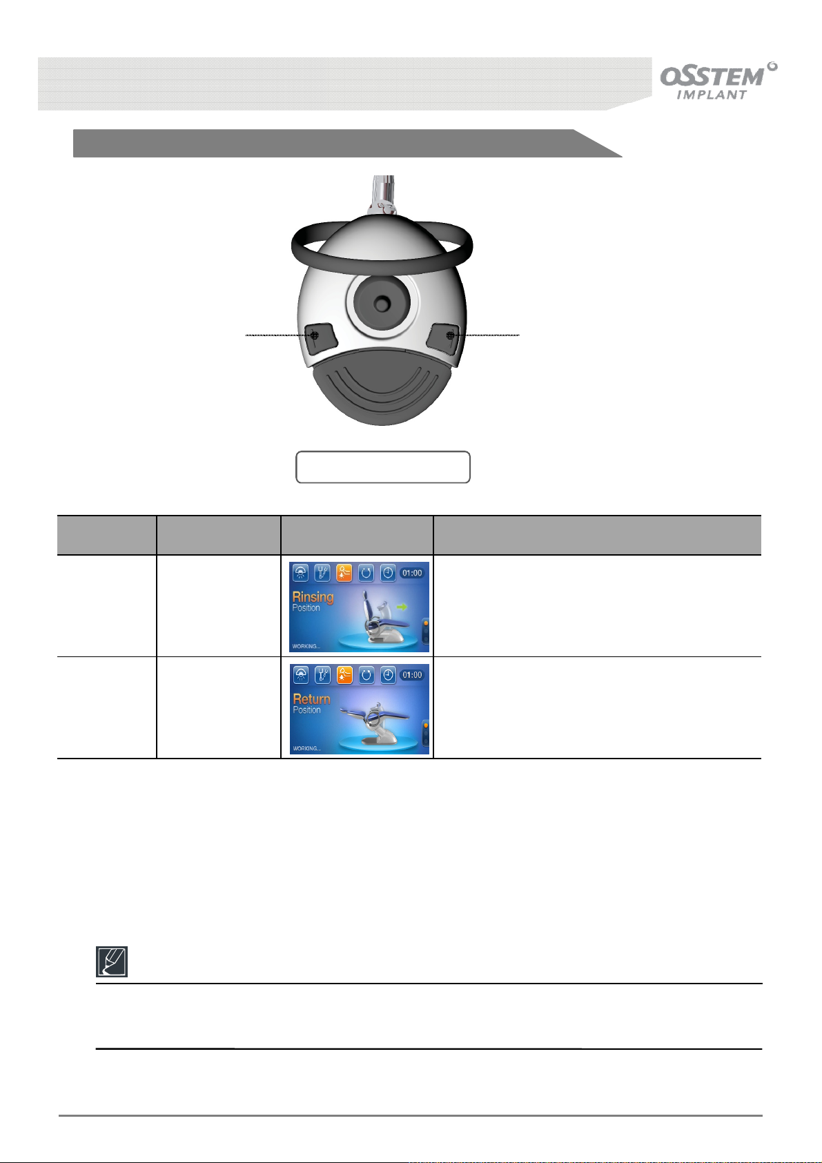
3-5-3. Foot Controller Chair Software
①②
[Fig. 13] Foot Controller
Button Function LCD Screen Description
①
②
Rinsing Position
Moves to the spittoon location for the patient
to rinse his/her oral cavity post-treatment.
Moves to the previous treatment position after
Return Position
the patient has rinsed his/her oral cavity.
Reference
The Chair Positioning Memory Button only needs to be pressed once to position the Chair
accordingly.
K3
UNIT CHAIR [OS-UM-C002 Ver.2]
33
Page 34
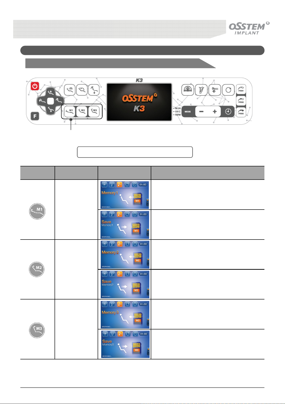
3-6. Chair Software-Changing the Settings
3-6-1. Doctor's Table Panel Chair Software-Changing the Settings
Chair Positionng Memory
Button
[Fig. 14] Composition of the Doctor’s Table Panel
Button Function LCD Screen Description
Memory 1
Memory 2
Memory 3
Moves to the position saved in Memory 1.
Pressing the Memory 1 button for more than
five seconds saves the current position to
Memory 1.
Moves to the position saved in Memory 2.
Pressing the Memory 2 button for more than
five seconds saves the current position to
Memory 2.
Moves to the position saved in Memory 3.
Pressing the Memory 3 button for more than
K3
UNIT CHAIR [OS-UM-C002 Ver.2]
five seconds saves the current position to
Memory 3.
34
Page 35
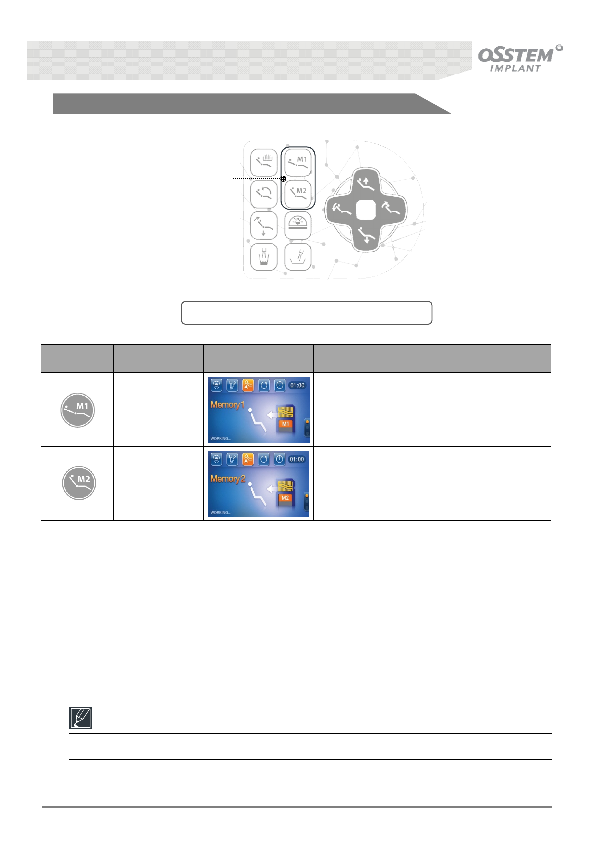
3-6-2. Assistant’s Panel Chair Software-Changing the Settings
Chair Positionng Memory
Button
[Fig. 15] Composition of the Assistant Table Panel
Button Function LCD Screen Description
Memory 1 Moves to the position saved in Memory 1.
Memory 2 Moves to the position saved in Memory 2.
Reference
Changing memory settings is only available on the Doctor's Table Panel.
K3
UNIT CHAIR [OS-UM-C002 Ver.2]
35
Page 36
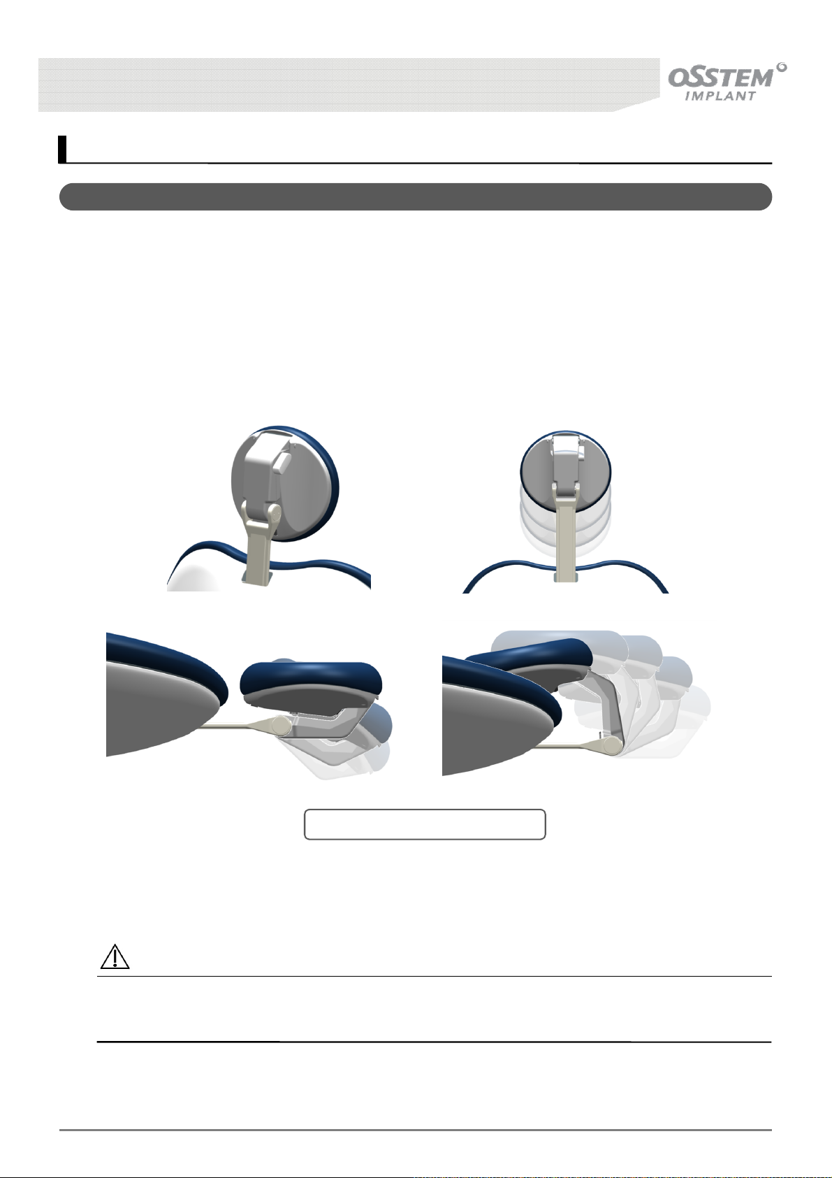
4. Patient Chair-Option
4-1. 2-Link Headrest
■ Method of Operation
The 2-Link Headrest can be adjusted according to each patient, as shown in
It can be rotated by pressing the operation button, rotating the two links to reach the desired angle,
then releasing the button; the angle is fixed once the button is released.
Additionally, the entire 2-Link Headrest can be moved up and down by pulling and pushing, to
accommodate patients of various upper body sizes.
Fig. 8
below.
Caution
Placing heavy weights on the Headrest can lead to damage of the product.
Please support the 2-Link Headrest with both hands whilst operating the product.
K3
UNIT CHAIR [OS-UM-C002 Ver.2]
[Fig. 16] 2-Link Headrest Function
36
Page 37
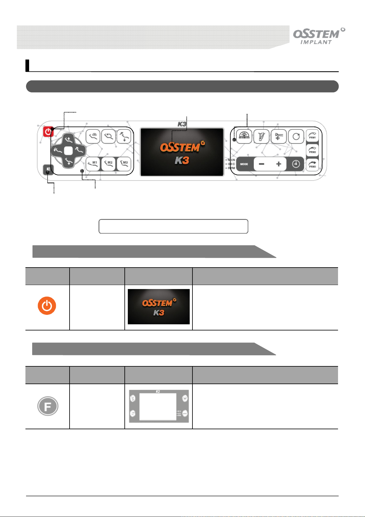
5. Doctor’s Interface
5-1. Doctor’s Table Panel
Film Viewer
Button
System Power Button
Patient Chair Positiong
Button
[Fig. 17] Composition of the Doctor’s Table Panel
LCD
Function Button
5-1-1. System Power Button
Button Function LCD Screen Description
System power
on/off
Switch the system on/off
5-1-2. Film Viewer Button
Button Function LCD Screen Description
FILM VIEWER
Film Viewer Displays patient x-ray
K3
UNIT CHAIR [OS-UM-C002 Ver.2]
37
Page 38
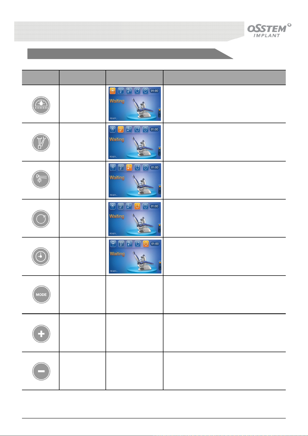
5-1-3. Function Button
Button Function LCD Screen Description
Dental Light
on/off
Hand-piece
Water Injection
on/off
Hand-piece
Optic
on/off
Hand-piece
Direction
Switch Dental Light on/off
Switch Hand-piece water injection on/off
Switch Hand-piece optic on/off
Switch Low speed Hand-piece direction of
rotation (clockwise, anti-clockwise)
Timer
Minute/Second/
RPM
Mode Selection
Increase
Minute/Second/
RPM
Reduce
Minute/Second/
RPM
Switch timer On/Off (hold for more than 3
seconds to reset the timer)
- Select mode to adjust minute/second/rpm
- Increase Minute/Second/RPM
- Reduce Minute/Second/RPM
K3
UNIT CHAIR [OS-UM-C002 Ver.2]
38
Page 39
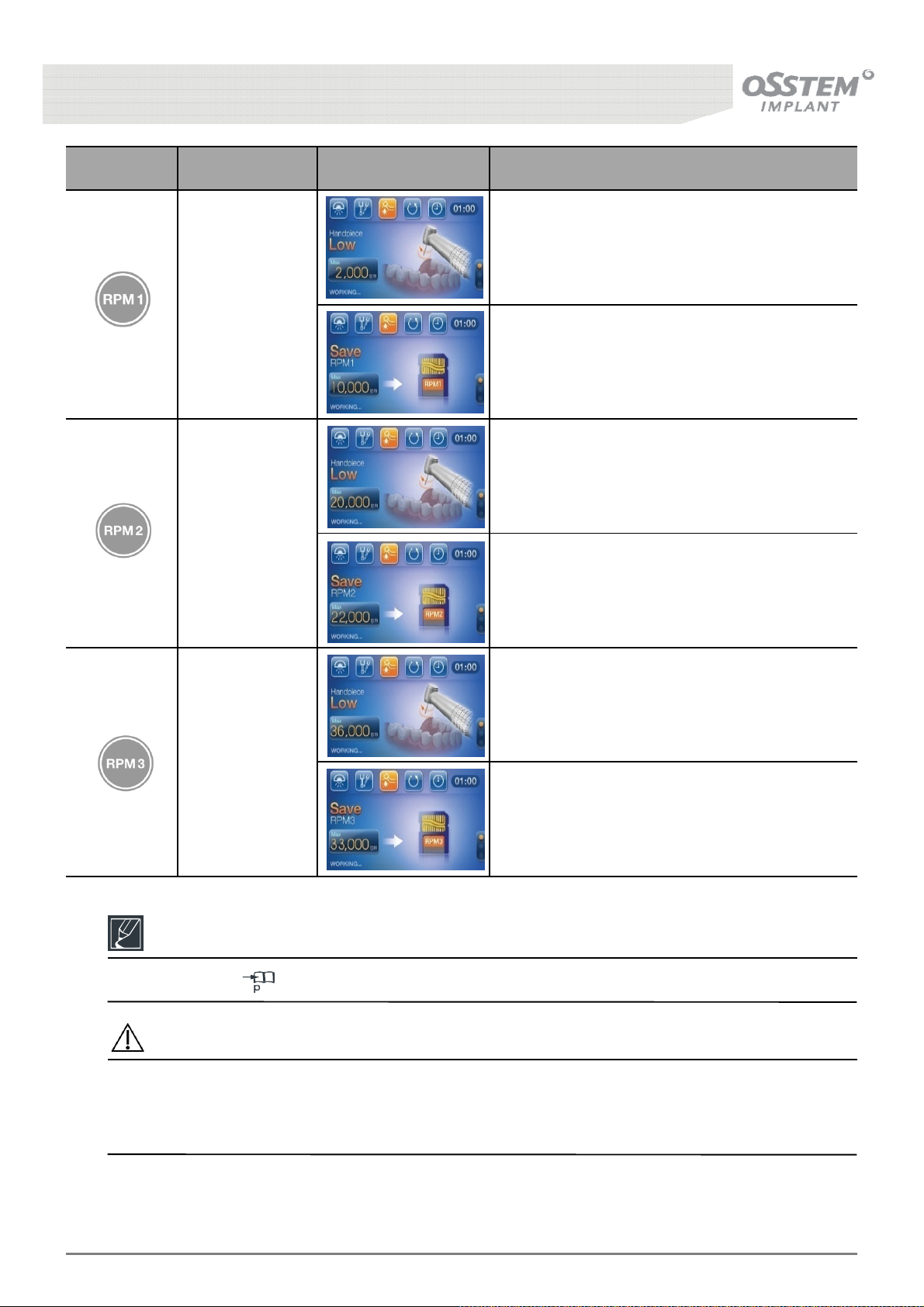
Button Function LCD Screen Description
Operates Low speed Hand-piece at the speed
saved in RPM1
RPM 1
Pressing the RPM1 button for more than 3
seconds saves the current speed to RPM1
Operates Low speed Hand-piece at the speed
saved in RPM2
RPM 2
Pressing the RPM2 button for more than 3
seconds saves the current speed to RPM2
Operates Low speed Hand-piece at the speed
saved in RPM3
RPM 3
Pressing the RPM3 button for more than 3
seconds saves the current speed to RPM3
Reference
Please refer to 24,31,34 for descriptions of the Patient Chair Positioning Button.
Caution
(In case of fluid spillage on the control panel) fluid may leak into the panel, resulting in damage or
malfunction, so please take care.
Operating the panel with sharp tools etc. can result in ripping, or any other damage, of the panel.
K3
UNIT CHAIR [OS-UM-C002 Ver.2]
39
Page 40
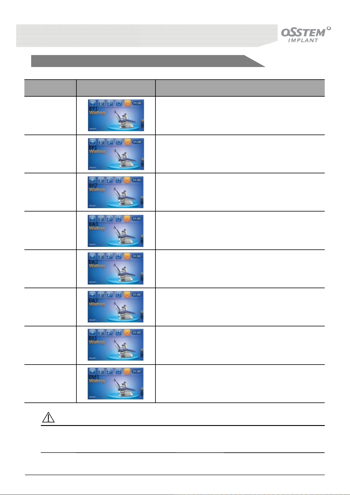
5-1-4. Error Message
Code LCD Screen Description
[ET1] Dr. Table Key Failure(23 items)
[EF1] Foot Key Failure(6 items)
{EF2] Foot Pedal Failure(1 item)
{EA1] Assistant Table Key Failure(10 items)
{EA2]
{EA3]
[ES1] Abnormality of water supply sensor
[EM1] Abnormality of emergency switch
Abnormality of forced water supply to assistant
Table cup
Abnormality of forced water supply to assistant
Table spittoon
Caution
If liquid is spilt on the Control Panel, please wipe the liquid immediately using dry cloth. Otherwise,
Product failure or electric shock may occur.
K3
UNIT CHAIR [OS-UM-C002 Ver.2]
40
Page 41
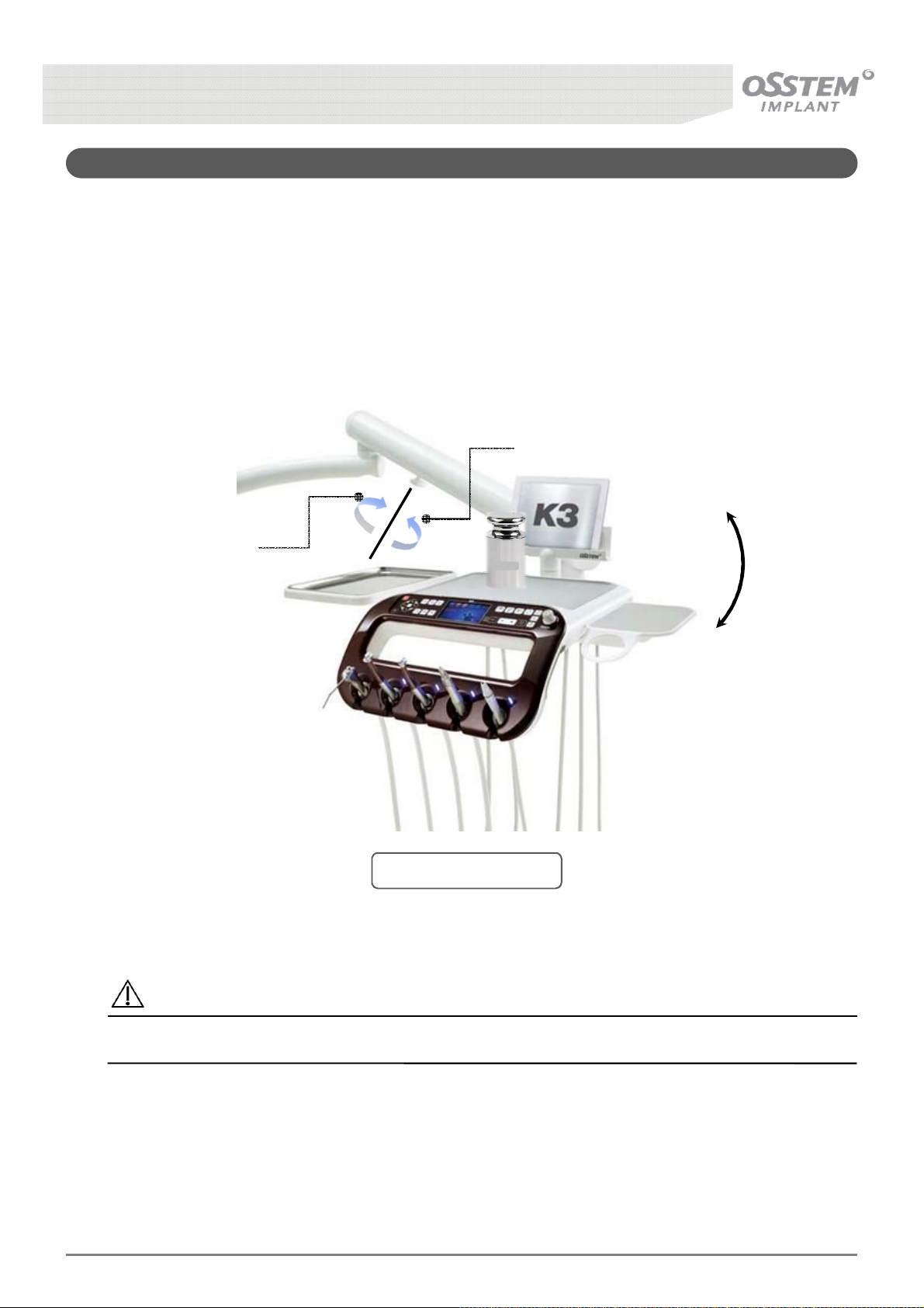
5-2. Positioning the Doctor’s Table
■ Method of Operation
The Doctor’s Table can be fixed in the desired position.
Turning the knob clockwise tightens the Arm, whilst turning it anti-clockwise loosens the Arm so the
Table can be moved.
Brake off
Brake on
5kg
Caution
Placing loads greater than 5 Kg on the Doctor’s Table can cause damage to the product.
K3
UNIT CHAIR [OS-UM-C002 Ver.2]
[Fig. 18] Doctor Table
41
Page 42
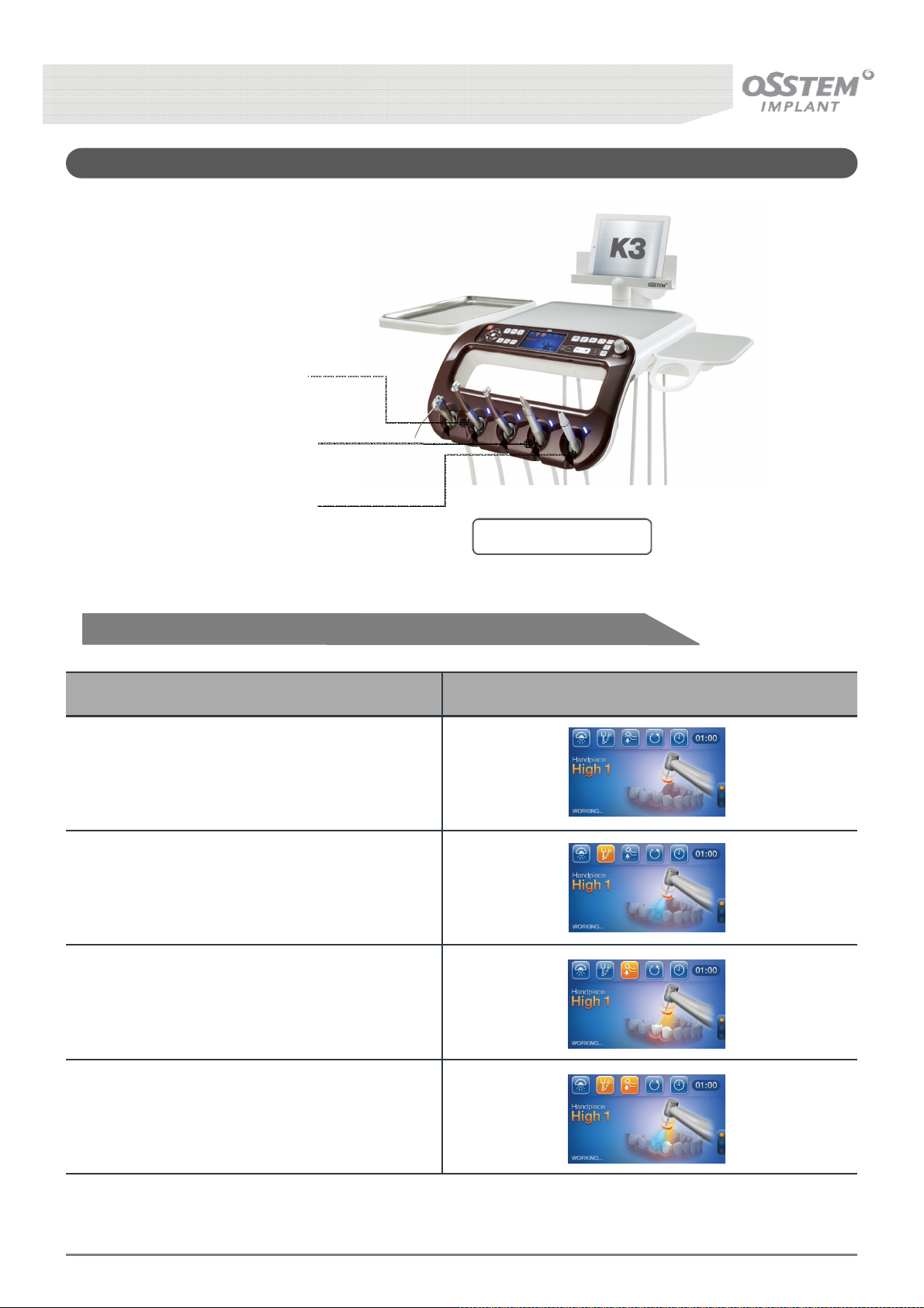
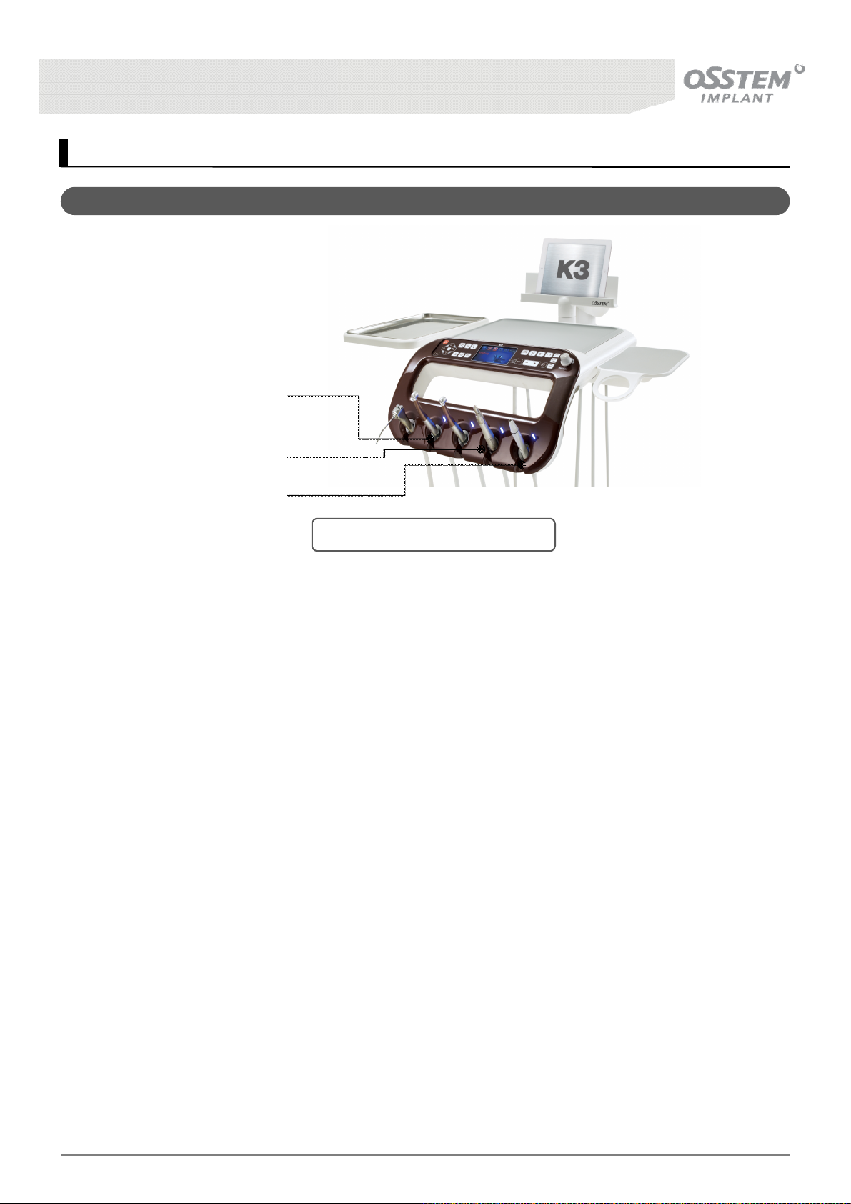
5-3. Instrument
High speed
Hand-piece
Low speed
Hand-piece
SCALER
[Fig. 19] Instrument
5-3-1. High Speed Hand-Piece
Status LCD Display
Hand-piece Water Injection OFF,
Hand-piece optic OFF
Hand-piece Water Injection ON,
Hand-piece optic OFF
Hand-piece Water Injection OFF,
Hand-piece optic ON
Hand-piece Water Injection ON,
Hand-piece optic ON
K3
UNIT CHAIR [OS-UM-C002 Ver.2]
42
Page 43
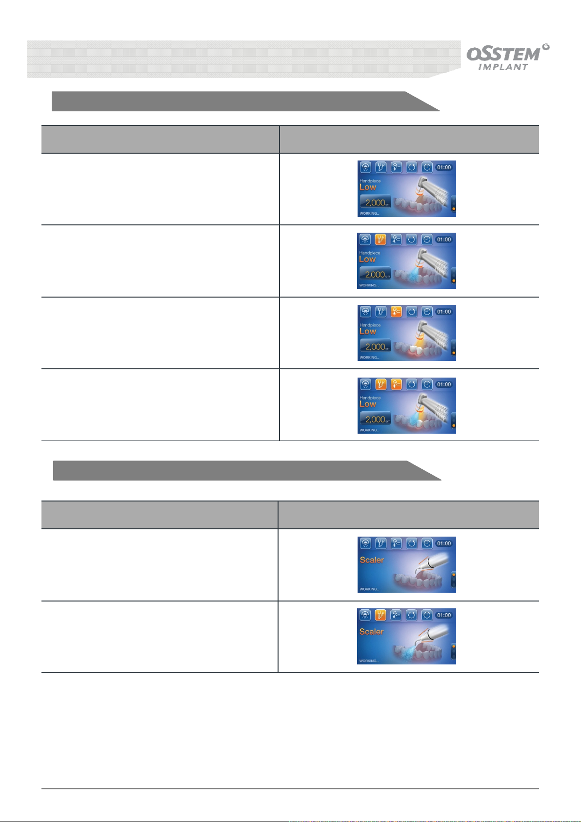
5-3-2. Low Speed Hand-Piece
Status LCD Display
Hand-piece Water Injection OFF,
Hand-piece optic OFF
Hand-piece Water Injection ON,
Hand-piece optic OFF
Hand-piece Water Injection OFF,
Hand-piece optic ON
Hand-piece Water Injection ON,
Hand-piece optic ON
5-3-3. SCALER
Status LCD Display
Hand-piece Water Injection OFF
Hand-piece Water Injection ON
K3
UNIT CHAIR [OS-UM-C002 Ver.2]
43
Page 44
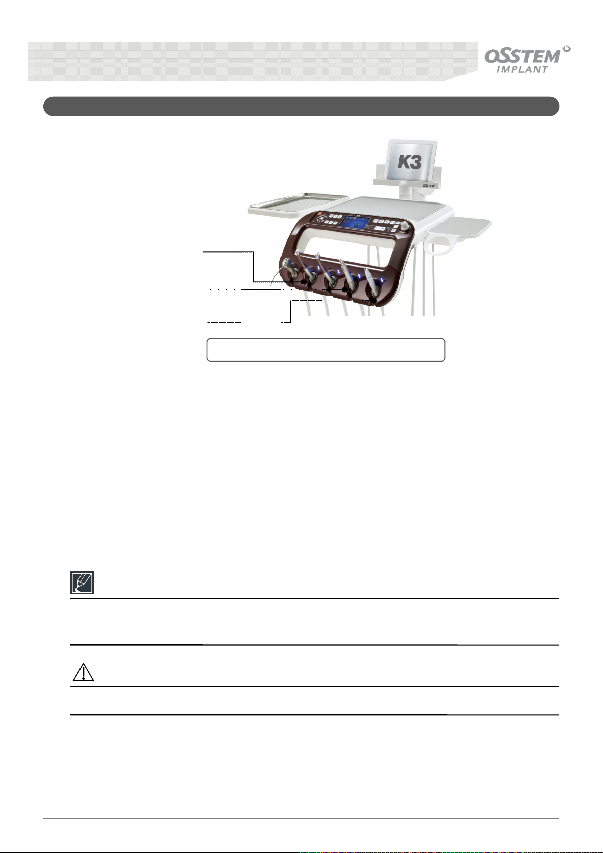
5-4. High Speed Hand-piece
High Speed
Hand-Piece
Low Speed
Hand-Piece
SCALER
[Fig. 20] Operation Method of the Hand-piece
■ Method of Operation
Pull out the High Speed Hand-piece from the instrument holder and press the pedal on the Foot
Controller to operate the High Speed Hand-piece.
The High Speed Hand-piece currently in use is displayed on the Table Panel (HIGH H.P1, HIGH H.P2)
Reference
Only the Hand-piece that was taken out first from the instrument holder operates, and during
Hand-piece operation Chair functions are temporarily halted for safety.
Caution
Do not hold the Hand-piece at the head while pressing the foot-controller pedal.
K3
UNIT CHAIR [OS-UM-C002 Ver.2]
44
Page 45
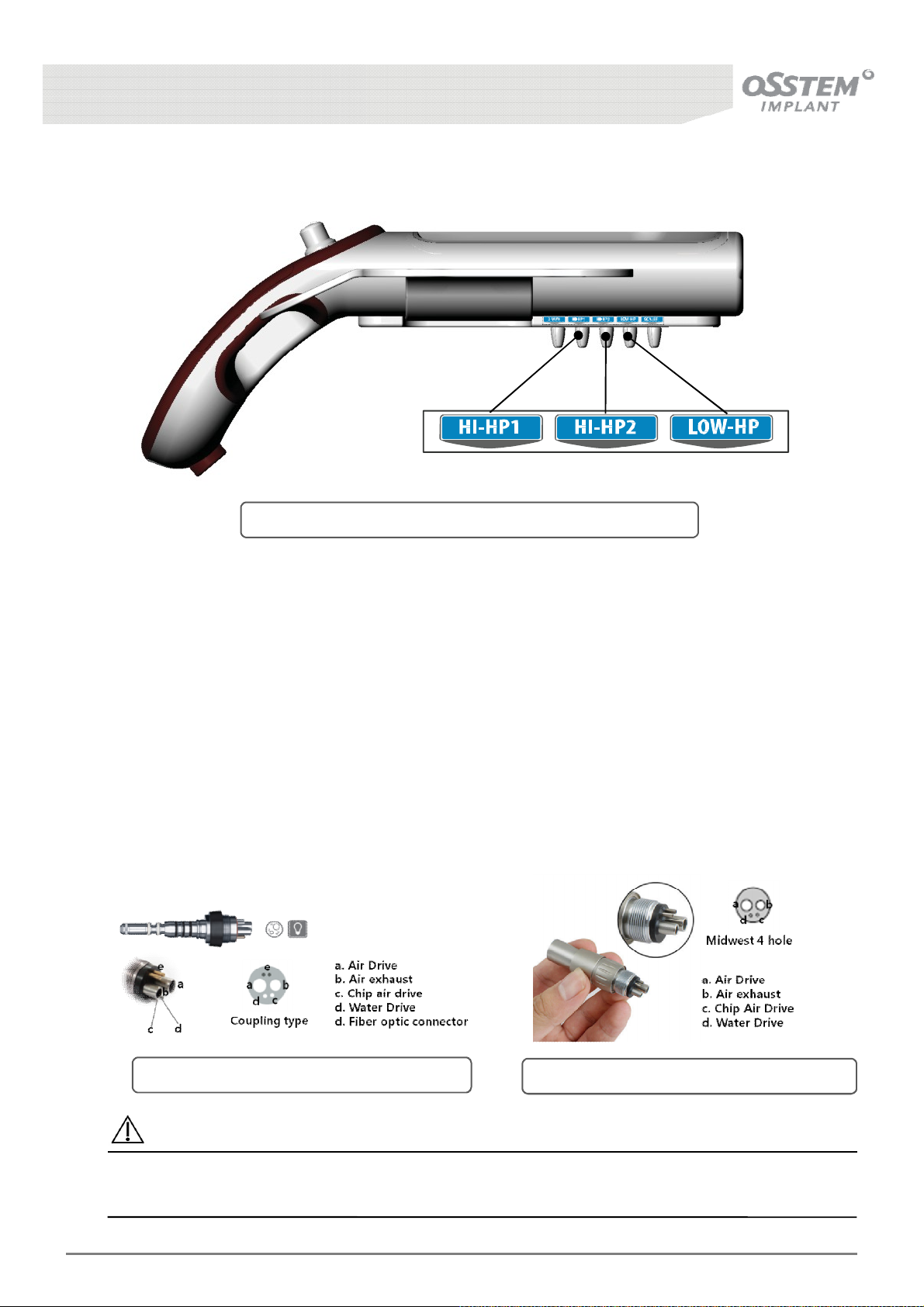
■ Method of Controlling the Amount of Water
[Fig. 21] Controlling the Amount of Water of the Hand-piece
- There are 5 water flow valves on the underside of the Table; turning the valves clockwise decreases
flow rate, and turning anti-clockwise increases flow rate.
- Pressure Gauge: Adjusts Table air pressure to 3kgf/㎠ (Hand-piece operation pressure)
■ Control of software
The Low Speed Hand-piece has two functions controlled by software.
- Hand-piece water supply ON/OFF
- Hand-piece optic ON/OFF (In case of High Speed Hand-Piece)
■ Control of software
[Fig. 22] The type of High Speed Hand-Piece
[Fig. 23] The type of Low Speed Hand-Piece
Caution
When more than one Hand-piece is taken out of the instrument holder at once, the Hand-piece
taken out first operates.
K3
UNIT CHAIR [OS-UM-C002 Ver.2]
45
Page 46
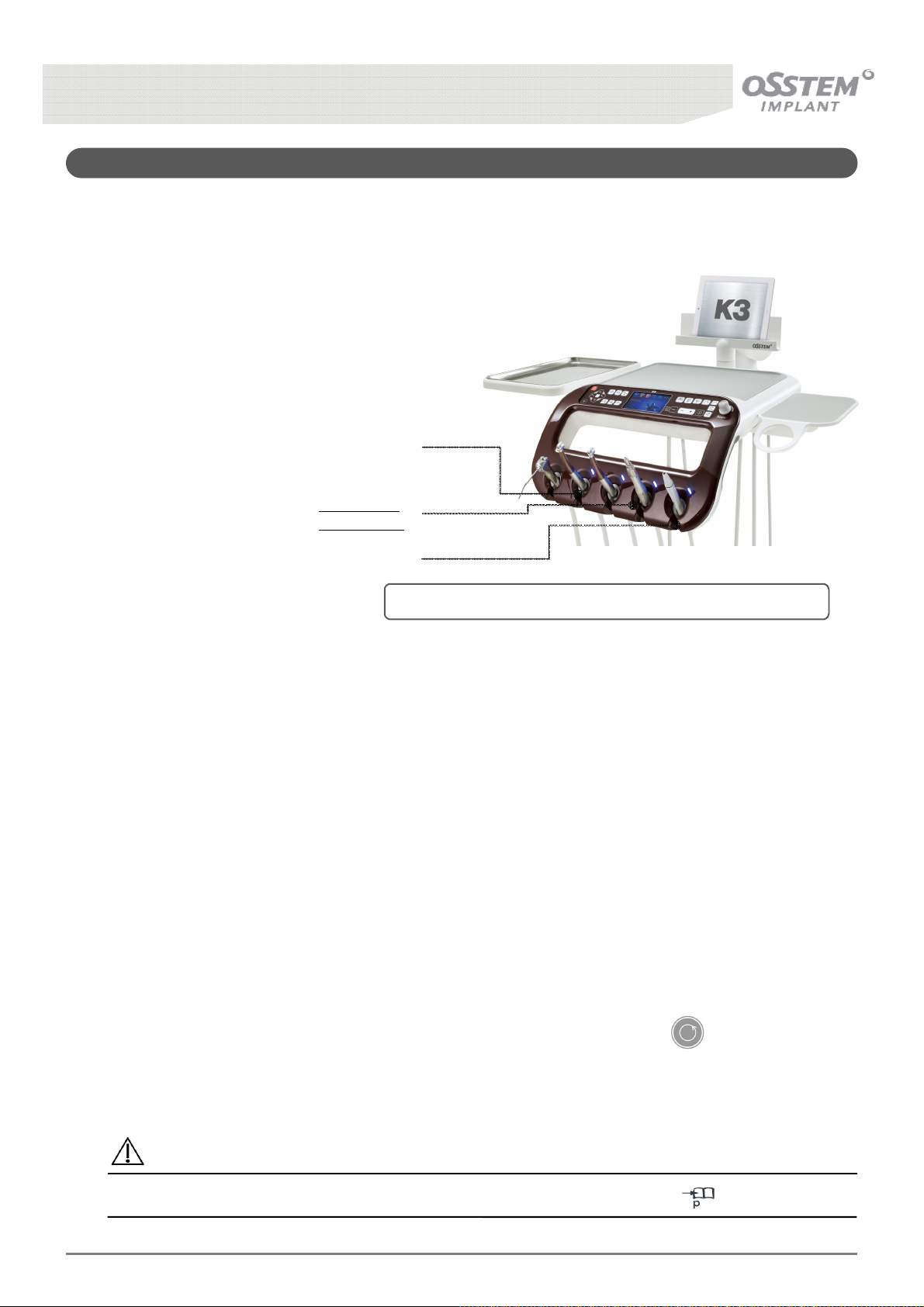
5-5. Low Speed Hand-piece
■ Method of Operation
Pull out the Low Speed Hand-piece from the
instrument holder and press the Foot Controller
pedal to operate the Hand-piece.
The Hand-piece speed can be controlled by how
strongly the user presses the pedal.
High Speed
Hand-Piece
Low Speed
Hand-Piece
SCALER
[Fig. 24] Operation Method of the Low Speed Hand-piece
■ Control of software
The Low Speed Hand-piece has four functions controlled by software.
- Hand-piece water supply ON/OFF
- Hand-piece optic ON/OFF
- Shift of directions of rotation
- Set Maximum RPM limit
■ The type of Low Speed Hand-piece that are compatible
The conditions of compatible Low Speed Hand-piece type are as below.
- Input Power: AC 24V
- Communication Interface: RS232
■ Shifting direction of rotation
To shift the rotational directions of Low Speed Hand-piece rotation, press the Button to reverse
the rotational direction. There is a lamp on each side of the Button, and the lamp indicates CCW
(counterclockwise) or CW (clockwise) when the button is pressed.
Caution
For the setting method of Low Speed Hand-Piece RPM and LCD Display, see 39, 43.
K3
UNIT CHAIR [OS-UM-C002 Ver.2]
46
Page 47
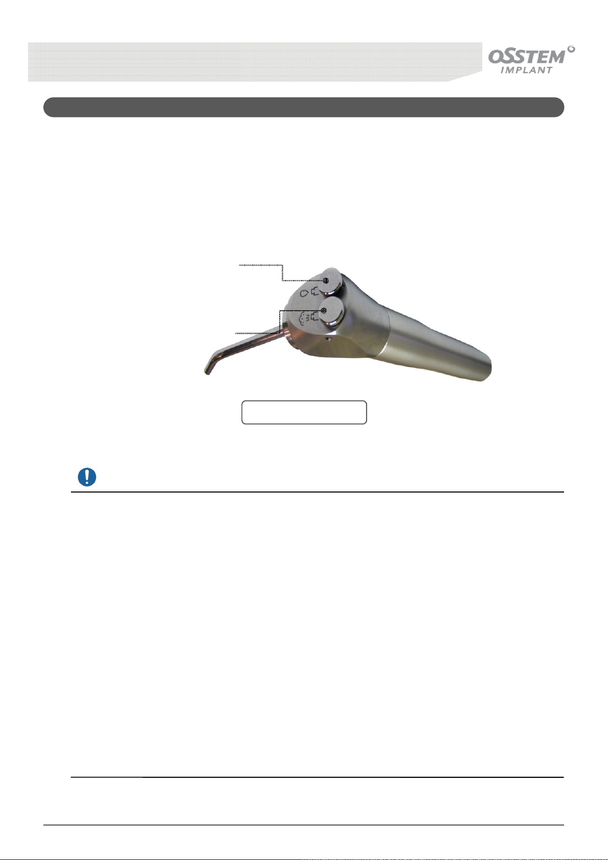
5-6. 3-Way Syringe
■ Method of Operation
3-Way Syringe has an air control button and a Water Control button, which may be used separately; if
you use them simultaneously, you can use the water spray function.
(3-Way Syringe Tip: ф 4 x 85 mm)
Water Control Button
Air Control Button
[Fig. 25] 3-Way Syringe
Mandatory action
Sterility procedure recommended for NON-STRILE medical devices
Sterilize the 3-Way syringe Nozzle provided by Osstem in its container with water vapor in an
autoclave in accordance with standard hospital procedure. The sterilization method suggested has
been validated according to the AAMI ST 79 in order to obtain a Sterility Assurance Level (SAL) of
10-6.
Sterilization method: steam, Cycle: Saturated steam with forced air removal AUTOCLAVE:
porous load or gravity, Temperature: 132℃, Exposure time: 7 minutes, Dry time : 15min and
Pressure for gravity autoclave: 2,5Bars/ 36-PSIG.
Other sterilization methods are possible but must be validated beforehand.
The autoclave must be validated by the hospital and regularly checked to guarantee the
recommended sterilization temperature is reached for the entire exposure time.
If sterilization containers with paper filter are used, it is advisable to use new filter for each
sterilization.
If after having following this sterilization method there is still water in the sterilization contains or
on/inside the device, the device must be dried and sterilization repeated.
K3
UNIT CHAIR [OS-UM-C002 Ver.2]
47
Page 48
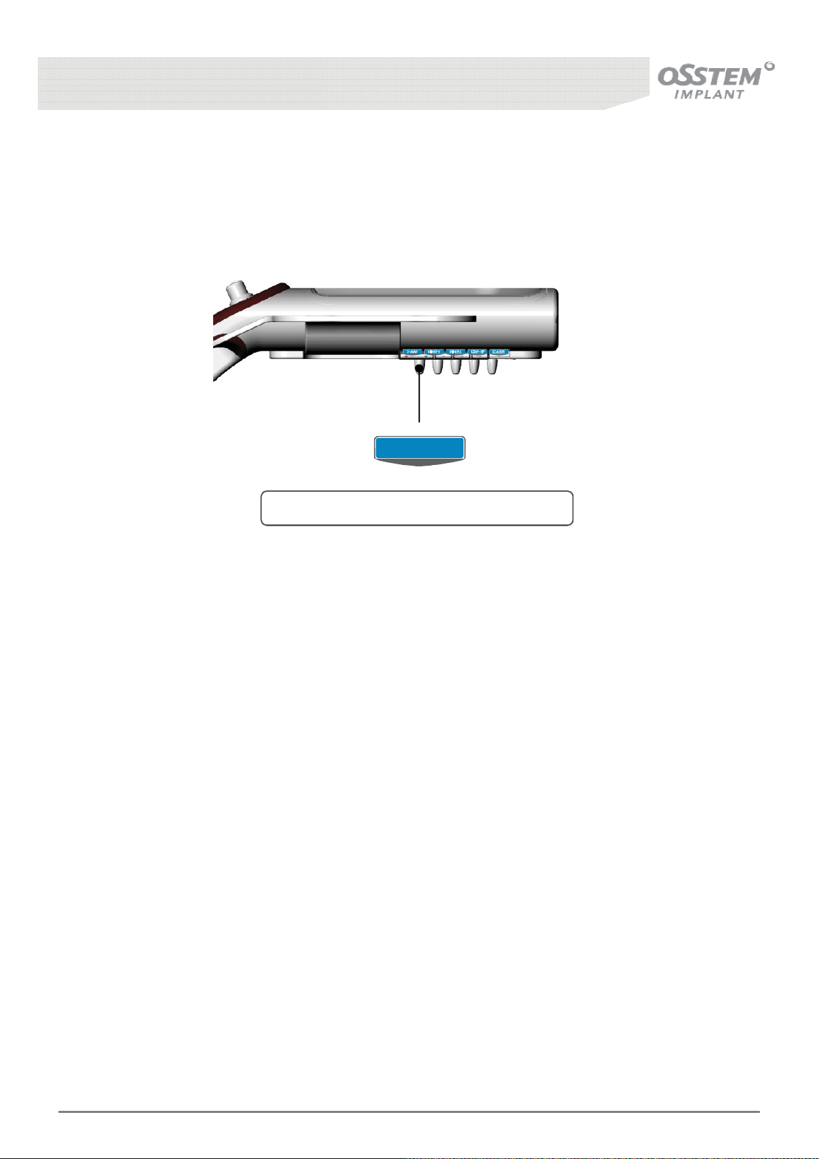
■ Method of Controlling the Amount of Water
To control the amount of water flowing through the 3-Way Syringe, you can use the water flow valve
on the underside of the table. Flow rate decreases if you turn it clockwise and increases if you turn it
anti-clockwise.
3-WAY
[Fig. 26] 3-Way Syringe Water Volume Control
K3
UNIT CHAIR [OS-UM-C002 Ver.2]
48
Page 49
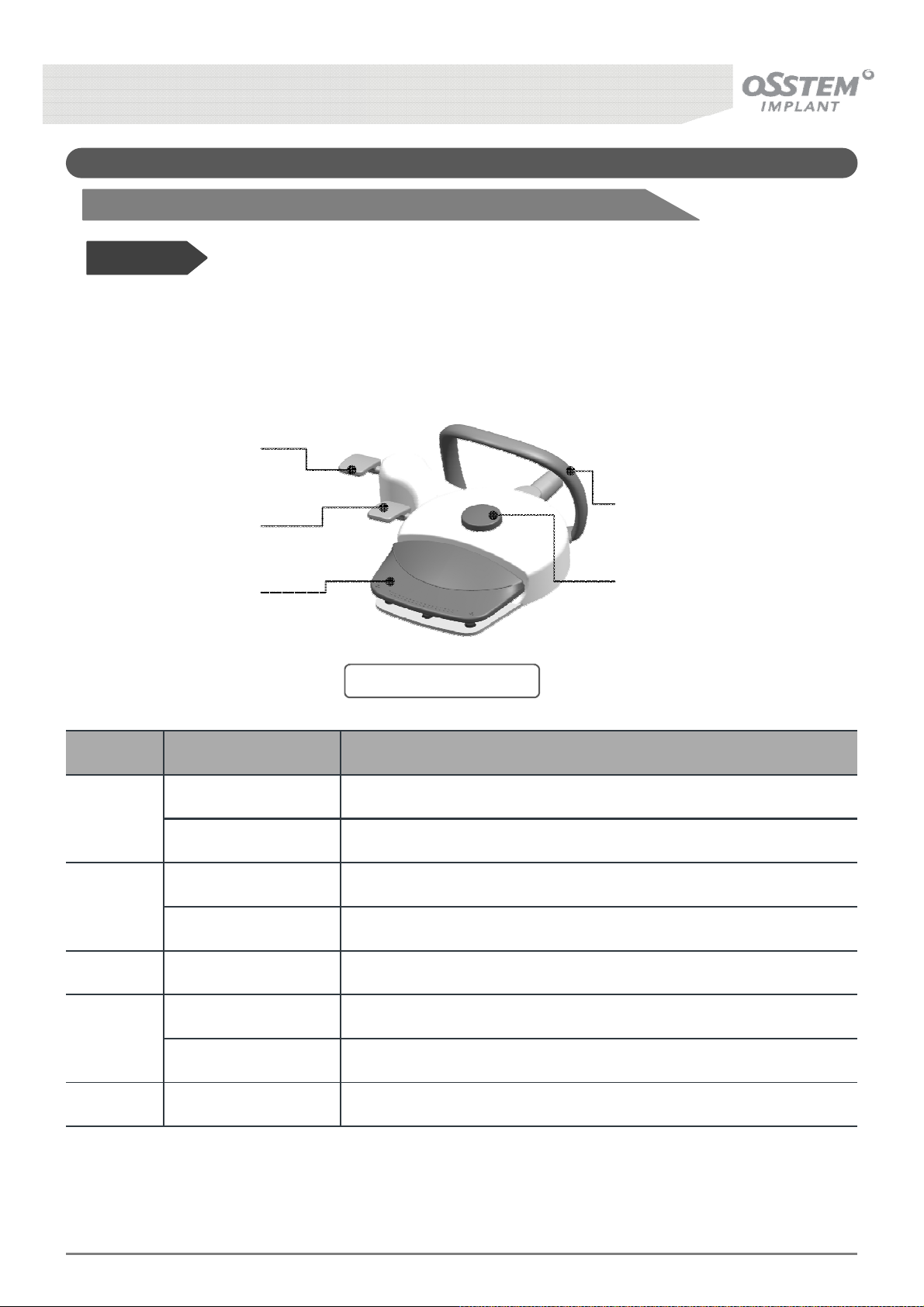
5-7. Foot Controller
Before Use!
• Foot controller can control the functions necessary for chair operation, and enables shifting
between automatic and manual operation of the chair. Likewise, you can control the speed of
High Speed Hand-Piece and Low Speed Hand-Piece.
①
②
⑤
③
④
[Fig. 27] Foot Controller
No. Function Method of operation
Backrest UP The Backrest moves UP when pushed right
Backrest DOWN The Backrest moves DOWN when pushed left
①
Chair UP The chair moves UP when pushed forward
Chair DOWN The chair moves DOWN when pushed backward
②
③
④
⑤
Return Position Return to the position before rinsing
Rinsing Position Move to the position for rinsing
Reference
Emergency Stop Device (ESB: Emergency Stop Button)
The Foot Controller Pedal includes the Emergency Stop Function. If an emergency occurs while
operating the chair, step on the Pedal to stop its operation automatically.
K3
UNIT CHAIR [OS-UM-C002 Ver.2]
Pedal Used to operate Hand-piece and Scaler
Footrest Move the Foot Controller with foot
49
Page 50
6. Doctor’s Interface - Option
6-1. SCALER
High Speed
Hand-Piece
Low Speed
Hand-Piece
SCALER
[Fig. 28] Scaler Operation Method
■ Method of Operation
Pull out the Scaler from the Instrument holder and step on the Foot Controller Pedal to operate the
Scaler with one touch; you need not keep stepping on the Foot Controller during treatment, offering
convenience during treatment. Stop the Scaler by stepping on the Foot Controller once more.
■ Control of software
The Scaler has two functions controlled by software.
- Scaler water supply ON/OFF
- Pedal signal ON/OFF
■ The type of Scaler that are compatible
The conditions of compatible Sealer type are as below.
- Input Power: AC 24V
- Operation Switch Signal: AC Power Contact
K3
UNIT CHAIR [OS-UM-C002 Ver.2]
50
Page 51
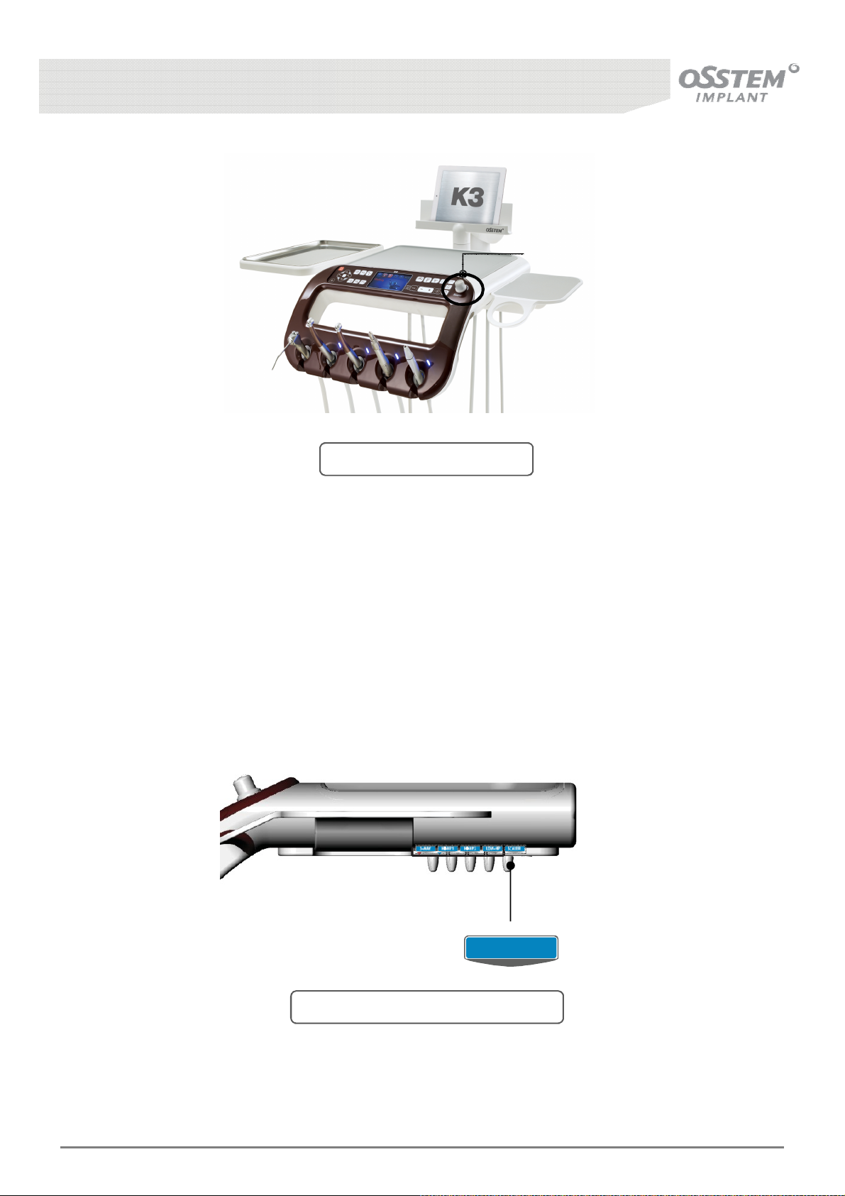
Handle
[Fig. 29] Scaler Power Control
■ Power Control Method
Turn the power control knob located at the front of the Table Panel clockwise to increase
Scaler power.
■ Method of Controlling the Amount of Water
As for the Scaler method of controlling the amount of water, you can use the water flow valve on the
underside of the table. Flow rate decreases if you turn it clockwise and increases if you turn it
anti-clockwise.
Scaler
[Fig. 30] Scaler Water Volume Control
K3
UNIT CHAIR [OS-UM-C002 Ver.2]
51
Page 52
6-2. Foot Controller - Option
6-2-1. Lever Type Foot Controller
Before Use!
• Foot controller can control the functions necessary for chair operation, and enables shifting between
automatic and manual operation of the chair. Likewise, you can control the speed of High Speed Hand-
Piece and Low Speed Hand-Piece.
①
⑤
②
③
[Fig. 31] Foot Controller
④
No. Function Method of operation
Backrest DOWN Press lever down to move backrest downward
①
Backrest UP Push lever up to move backrest upward
Chair DOWN Press lever down to move seat downward
②
Chair UP Push lever up to move seat upward
③
④
Pedal Used to operate Hand-piece and Scaler
Rinsing Position Press button once to move to rinsing position
Return Position Press once more to return to the position prior to rinsing
⑤
K3
UNIT CHAIR [OS-UM-C002 Ver.2]
Footrest Change the position using a foot
52
Page 53
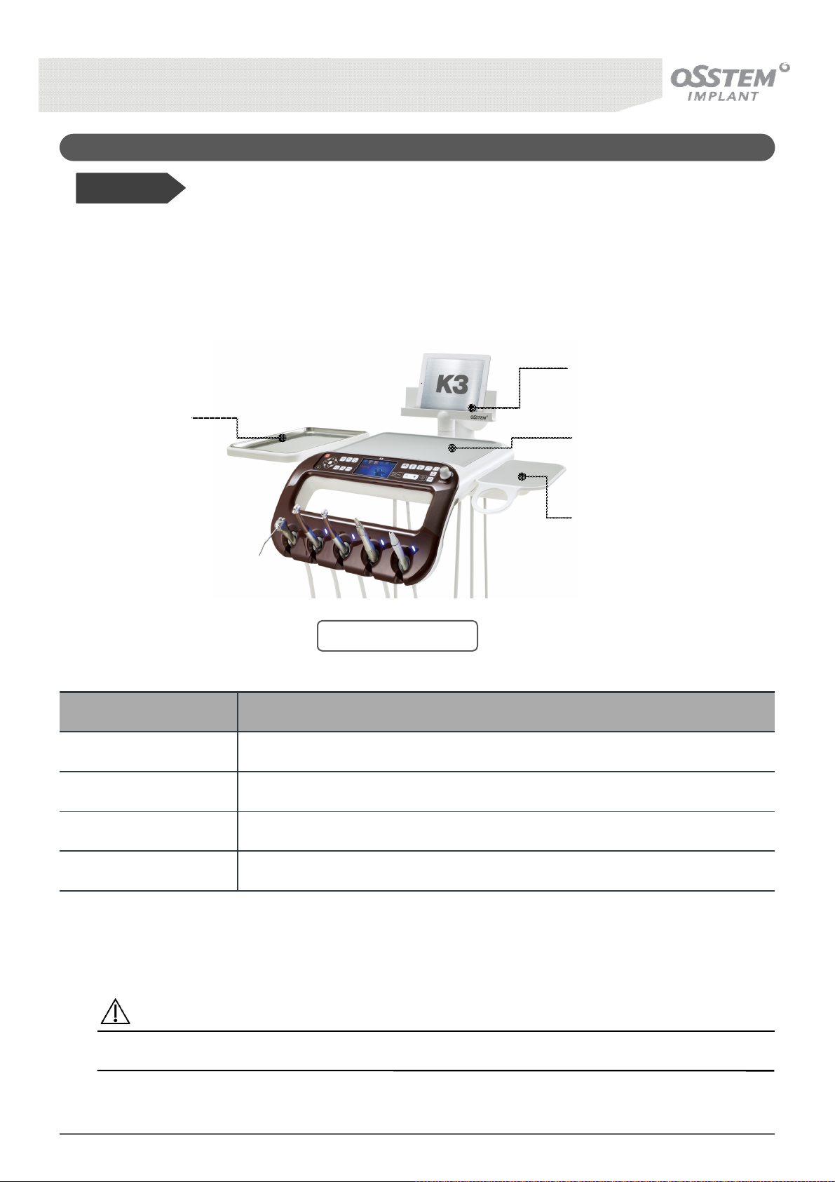
6-3. Other Options
Before Use!
• These are optional accessories designed specifically for the Unit Chair, to improve convenience of the
user.
Chart Holder
Extension Table
Silicone Mat
Mouse Pad
[Fig. 32] Doctor Table
Name Function and Method of Operation
Extension Table
Chart Holder
Mouse Pad
Silicone Mat
Provides additional space for equipment placement
Holds the patient’s treatment chart
Mouse Pad for operating visual material and treatment chart
Prevents slippage of equipment and other items placed on the mat
Caution
Placing loads greater than 5 kg on the Doctor’s Table can cause damage to the product.
K3
UNIT CHAIR [OS-UM-C002 Ver.2]
53
Page 54
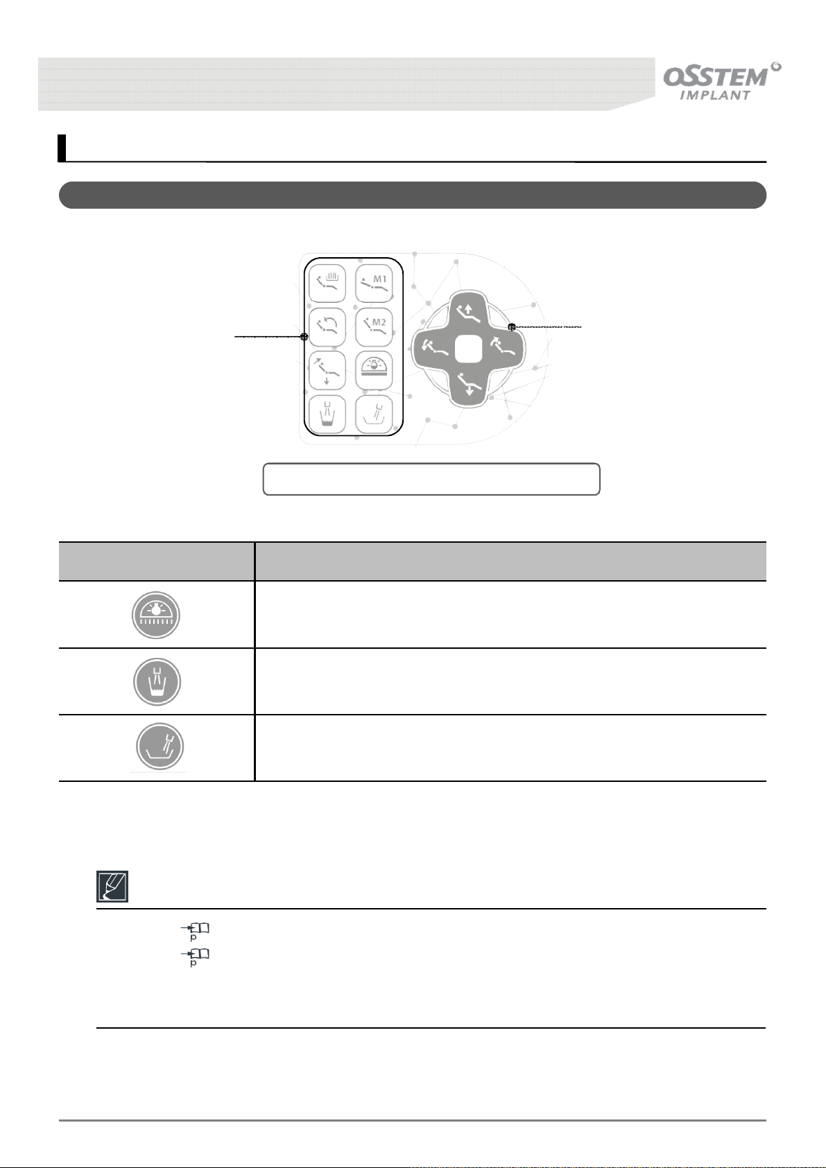
7. Assistant’s Interface
7-1. Assistant Table Panel
Function Button
[Fig. 33] Composition of the Assistant Table Panel
Button Description
Dental Light ON / OFF Function
Supplies Cup Water when button is pressed.
Chair Positioning
Button
Reference
Refer to 25 for information regarding the Chair Positioning Button.
Refer to 32, 35 for information regarding other Function Buttons.
Manual operation buttons only function while the button is held, whereas automatic operation
buttons only need to be pressed once.
K3
UNIT CHAIR [OS-UM-C002 Ver.2]
Injects Spittoon Water when button is pressed
54
Page 55
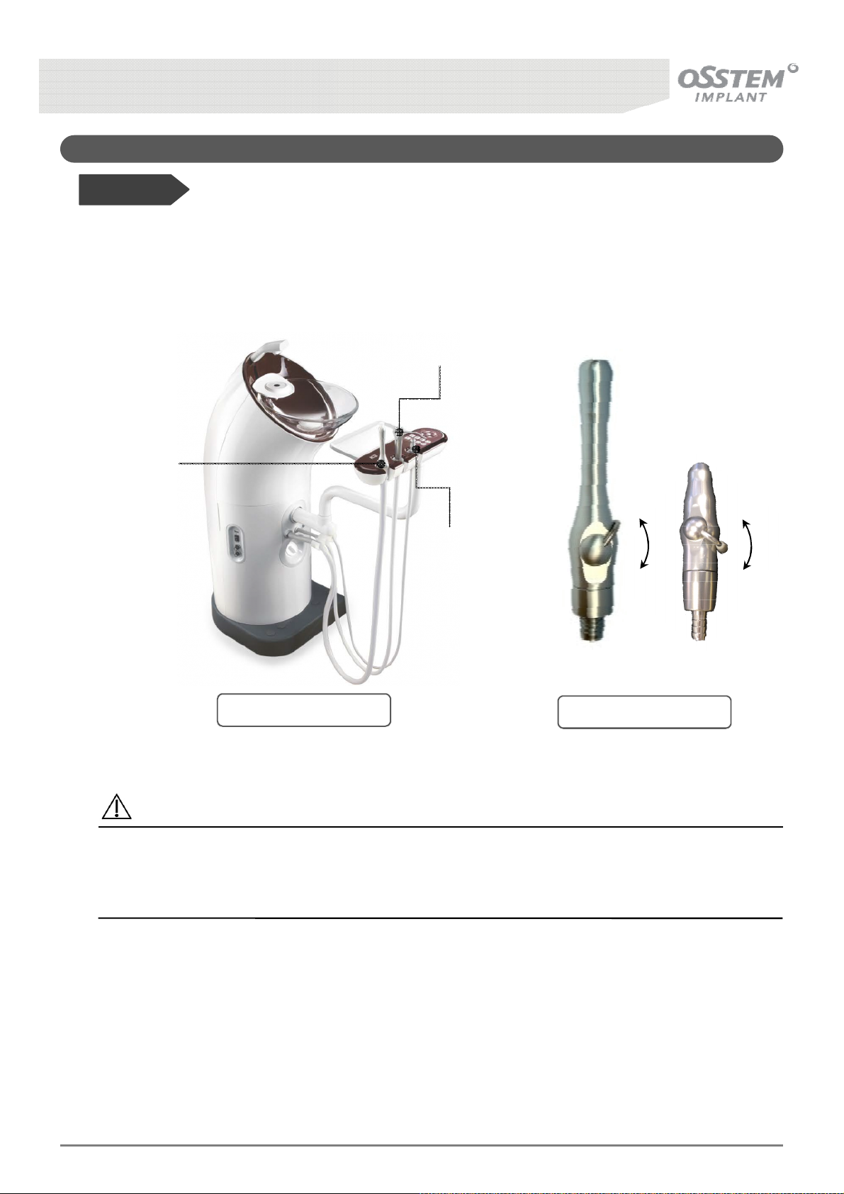
7-2. Saliva Ejector
Before Use!
• Equipment for removing saliva and other material from the oral cavity during treatment. Pulling out the
Saliva Ejector from the Assist Table Holder powers on the Suction Unit.
3-Way Syringe
Saliva Ejector
(Large)
OFF
Saliva Ejector
(Small)
OFF
[Fig. 34] Assist Table
[Fig. 35] Saliva Ejector
Caution
Do not touch the Saliva Ejector tip and the oral membrane during operation.
Insert a tip into the front of the Saliva Ejector for use.
- Replace the tip for every patient.
ON
ON
K3
UNIT CHAIR [OS-UM-C002 Ver.2]
55
Page 56
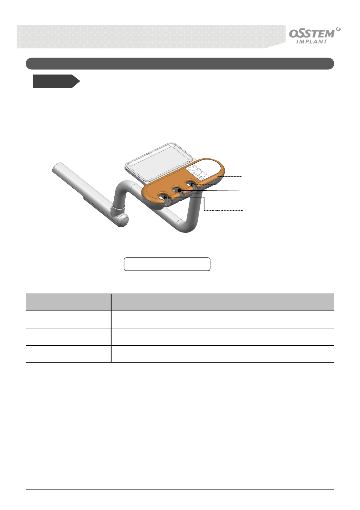
7-3. Assistant Table Holder
Before Use!
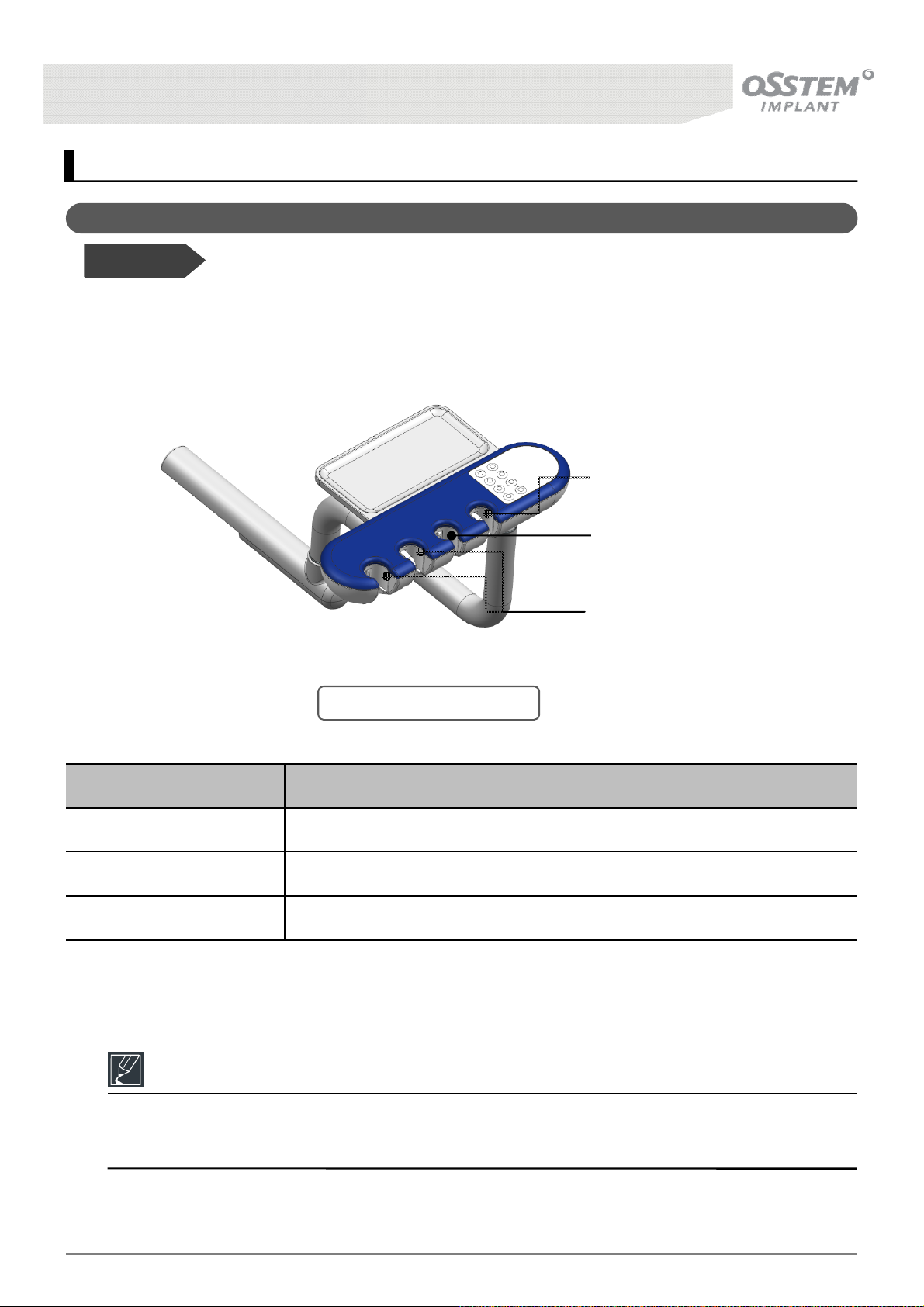
• Holds Saliva Ejector/3-Way Syringe, and micro switches can control the water used for the 3-Way
Syringe, as well as the suction device.
Saliva Ejector (Small)
Holder
3-Way Syringe Holder
Saliva Ejector (Large)
Holder
[Fig. 36] Assist Table Holder
Name Function and Method of Operation
Saliva Ejector (Small) Holder Holds Saliva Ejector (Small) and micro switch controls suction device
3-Way Syringe Holder Holds 3-Way Syringe and micro switch controls water
Saliva Ejector (Large) Holder Holds Saliva Ejector (Large) and micro switch controls suction device
K3
UNIT CHAIR [OS-UM-C002 Ver.2]
56
Page 57
8. Assistant’s Interface - Option
8-1. Assistant Table Holder
Before Use!
• Holds Saliva Ejector/3-Way Syringe, and micro switches can control the water used for the 3-Way
Syringe, as well as the suction device.
Saliva Ejector (Small)
Holder
3-Way Syringe Holder
Saliva Ejector (Large)
Holder
[Fig. 37] Assist Table Holder
Name Function and Method of Operation
Saliva Ejector (Small) Holder Holds Saliva Ejector (Small) and micro switch controls suction device
3-Way Syringe Holder Holds 3-Way Syringe and micro switch controls water
Saliva Ejector (Large) Holder Holds Saliva Ejector (Large) and micro switch controls suction device
Reference
The additional Saliva Ejector (Large) is used by the patient to suction his/her oral cavity.
- Used where oral rinsing is not carried out.
K3
UNIT CHAIR [OS-UM-C002 Ver.2]
57
Page 58
9. Water Dispensing System
9-1. Water Dispensing System
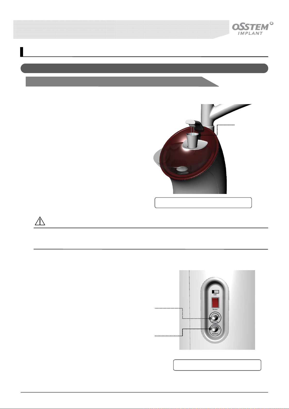
9-1-1. Automatic Water Dispensing - Basic Settings
■ Method of Operation
Controls water height using light sensors.
Automatically starts dispensing when it
detects the cup, and automatically stops at
a pre-determined height of water.
Capable of dispensing warm (< 42 °C)
water.
If the cup is removed during operation
dispensation stops, and the spittoon is
rinsed automatically 5 seconds later.
Light
Sensor
[Fig. 38] Automatic Water Supply Device
Caution
Use of disposable cups is recommended, and when using reusable cups they must be cleaned and
disinfected.
■ Water quantity control method
The amount of water dispensed is
controlled using the knob on the side of
the Unit Body {Fig. 39]. Turing clockwise
increases quantity.
Cup water quantity
control knob
Spittoon water
quantity control knob
K3
UNIT CHAIR [OS-UM-C002 Ver.2]
[Fig. 39] Automatic Water Dispenser
58
Page 59
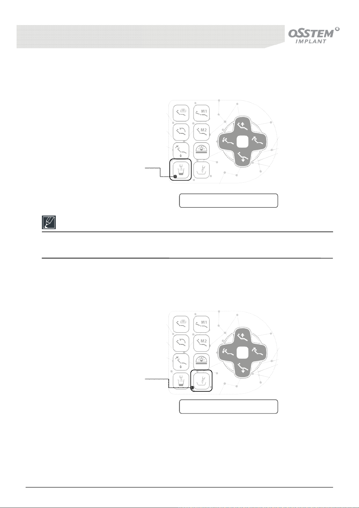
■ Manual Cup Water Dispenser
Water is dispensed into the cup while the Manual Cup Water Dispenser button, located on the
Assistant’s Panel, is held [Fig. 40]
Manual Cup Water
Dispense button
[Fig. 40] Manual Water Dispenser
Reference
Water dispensing stops when the button is released, and the spittoon is rinsed automatically after
5 seconds.
■ Manual Spittoon Water Dispenser
Water is dispensed to rinse the spittoon while the Manual Spittoon Water Dispenser button, located on
the Assistant’s Panel, is held [Fig. 41].
Manual Spittoon Water
Dispenser button
[Fig. 41] Manual Water Dispenser
K3
UNIT CHAIR [OS-UM-C002 Ver.2]
59
Page 60
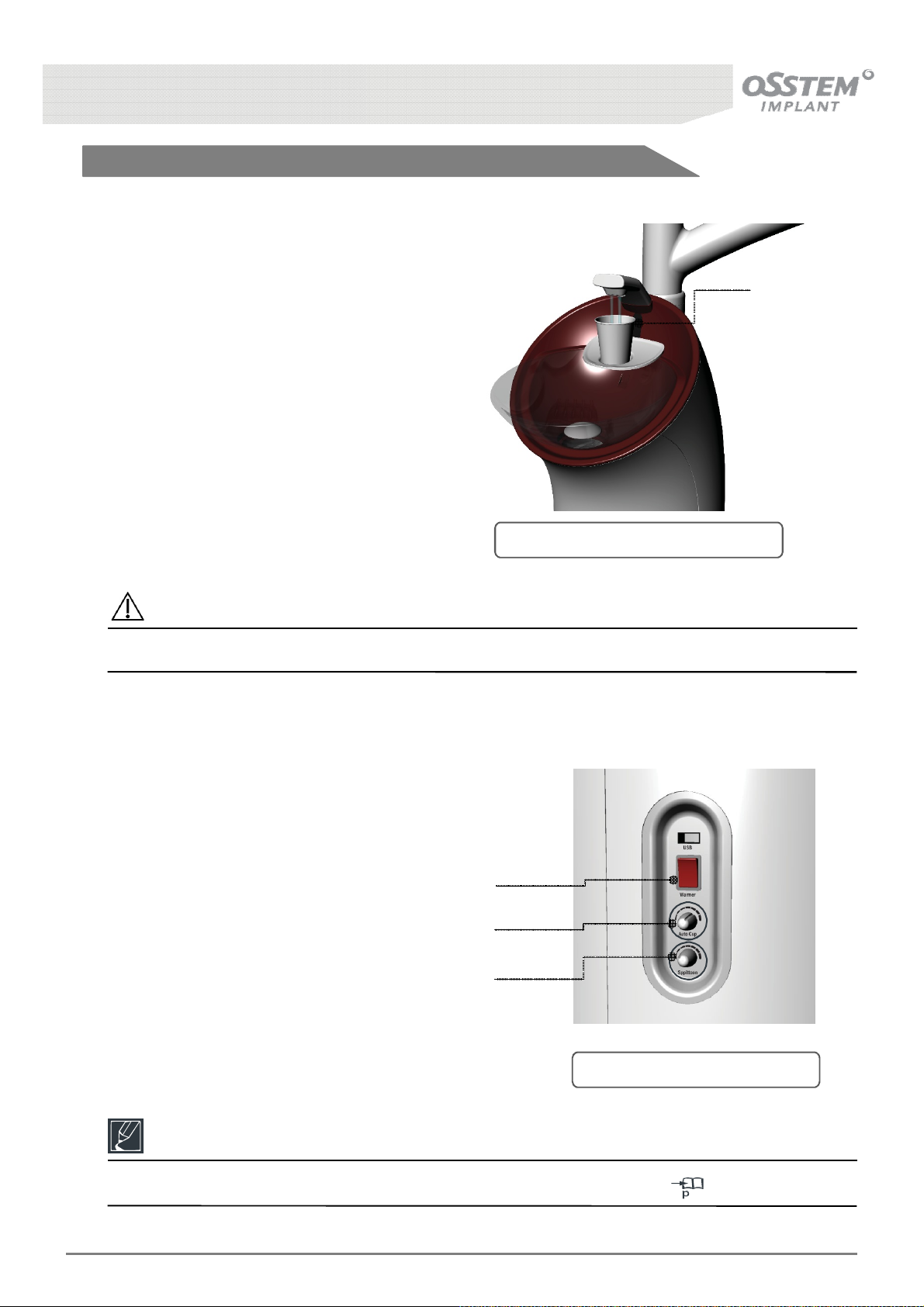
9-1-2. Semi-Automatic Water Dispenser – Option Setting
■ Method of Operation
After detecting cup presence with light
sensors water is dispensed for a pre-
determined period of time.
Capable of dispensing warm (< 42 ° C)
water.
If the cup is removed during operation
dispensation stops, and the spittoon is
rinsed automatically 5 seconds later.
[Fig. 42] Automatic Water Dispenser
Caution
Request customer service to change option settings for the semi-automatic water dispenser.
■ Water quantity control method
Light
Sensor
The amount of water dispensed is
controlled using the knob on the side of
the Unit Body [Fig. 43]. Turing clockwise
increases quantity.
Warm water ON/OFF switch
Dispense time control knob
(0 ~ 10 seconds)
Spittoon time control knob
(0 ~ 10 seconds)
[Fig. 43] Water Supply Dispenser
Reference
Manual Cup and Spittoon Water Dispensing method is identical to that in 59
K3
UNIT CHAIR [OS-UM-C002 Ver.2]
60
Page 61
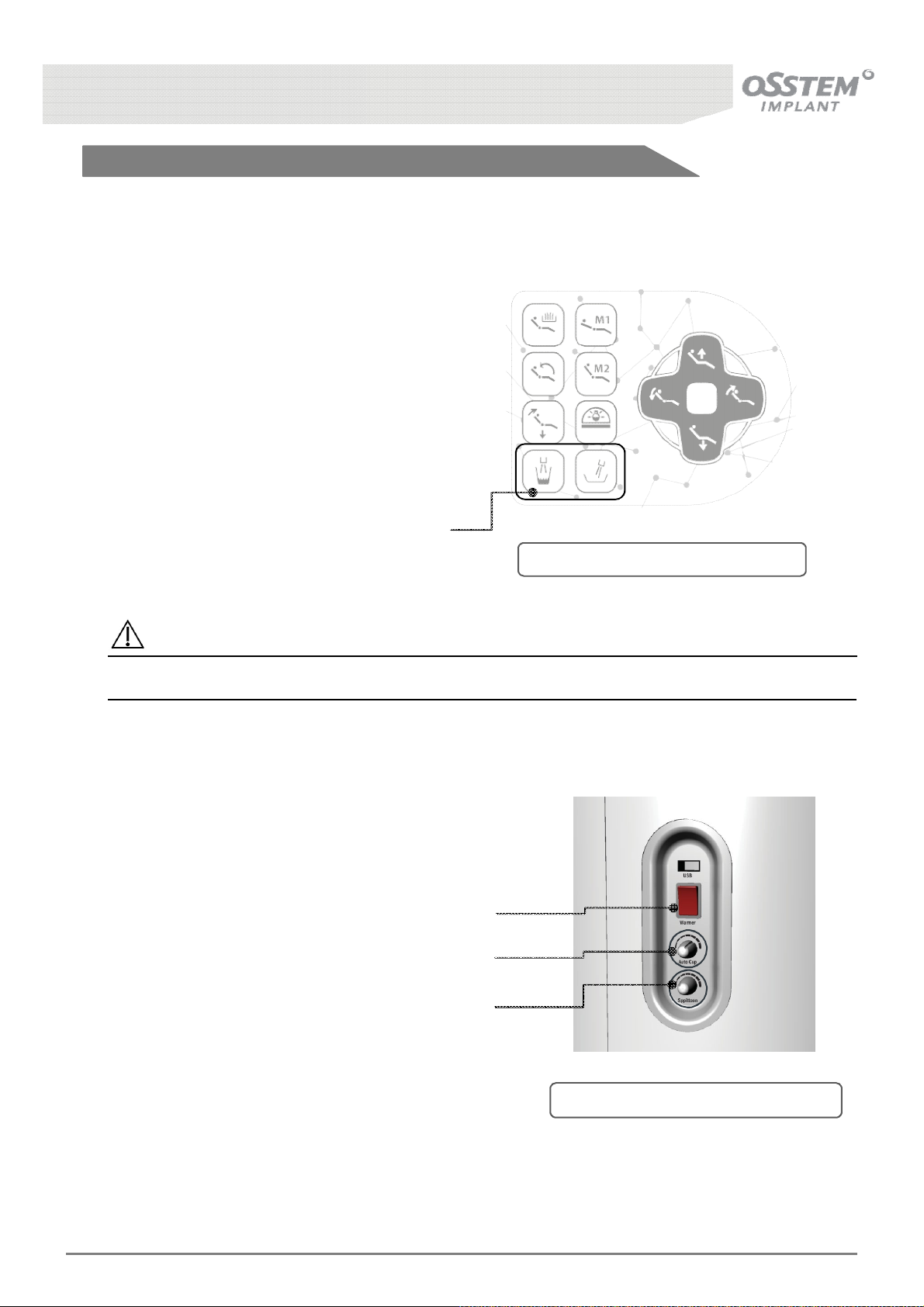
9-1-3. Manual Water Dispensing – Option Setting
■ Method of Operation
When the Manual Cup Water Dispenser button
is pressed water is dispensed for a pre-
determined period of time.
Capable of dispensing warm (< 42 ° C) water.
Water dispensation continues even if the cup is
removed during operation, and the spittoon is
rinsed automatically 5 seconds later.
Manual Cup/Spittoon Water
Dispenser button
[Fig. 44] Manual Water Supply Device
Caution
Request customer service to change option settings for the manual water dispenser.
■ Water quantity control method
The amount of water dispensed is
controlled using the knob on the side of
the Unit Body {Fig. 45]. Turing clockwise
increases quantity.
Warm water ON/OFF switch
Dispense time control knob
(0 ~ 10 seconds)
Spittoon time control knob
(0 ~ 10 seconds)
K3
UNIT CHAIR [OS-UM-C002 Ver.2]
[Fig. 45] Manual Water Supply Device
61
Page 62
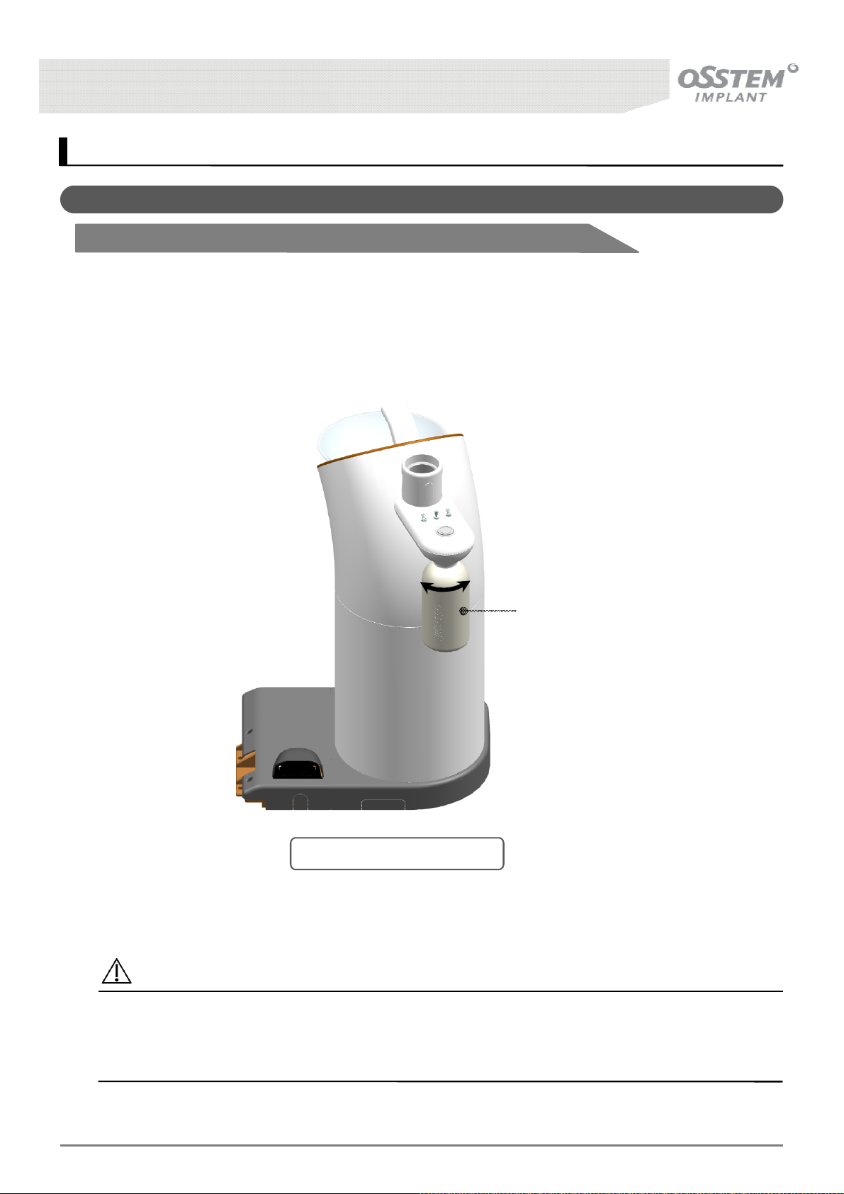
10. Water System - Option
10-1. Bottled Water System
10-1-1. Distilled Water Bottle
■ Method of Operation
The user can switch between tap and distilled water; turn the Water Bottle anti-clockwise to detach the
tank from the Unit.
Caution
CloseOpen
Distilled Water Bottle
[Fig. 46] Distilled Water Bottle
Only use OSSTEM Implant Water Bottles.
Replace immediately if the tank is altered or discolored.
Operational Temperature: +10℃ - +45℃.
K3
UNIT CHAIR [OS-UM-C002 Ver.2]
62
Page 63
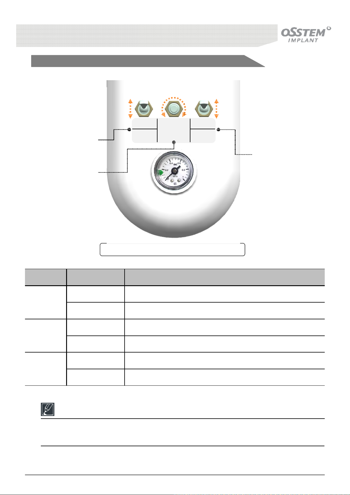
10-1-2. Switching between tap and distilled water
CITY ON
WATER
BOTTLE
PRESSURE
CONTROL
OFF
WATER
BOTTLE
①
BOTTLE
WATER
SUPPLY
②
③
[Fig. 47] Switching between tap and distilled water
No. Name Function and Method of Operation
CITY Tap water
①
BOTTLE Distilled water
ON Supply distilled water
②
OFF Cut off distilled water
Clockwise Increase distilled water supply pressure (flow rate increases)
③
Anti-clockwise Decrease distilled water supply pressure (flow rate decreases)
Reference
To use tap water : CITY + OFF.
To use distilled water : BOTTLE + ON
K3
UNIT CHAIR [OS-UM-C002 Ver.2]
63
Page 64
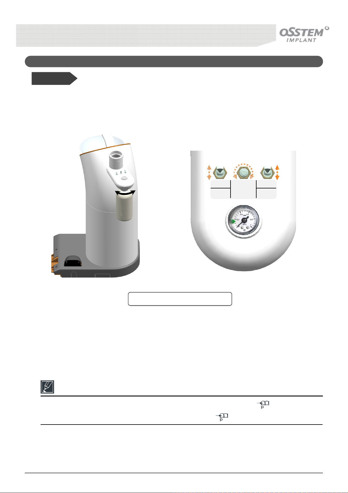
10-2. Waterline Cleaning System
Before Use!
• The Waterline Cleaning System is a semi-automatic cleaning function, to disinfect the Bottled Water
System and associated hoses using chemicals.
CITY ON
CloseOpen
BOTTLE
WATER
SUPPLY
[Fig. 48] Waterline Cleaning System
WATER
BOTTLE
PRESSURE
CONTROL
OFF
WATER
BOTTLE
Reference
Method of operation is identical to that when using distilled water, refer to 63.
For method of Waterline Cleaning using chemicals refer to 81.
K3
UNIT CHAIR [OS-UM-C002 Ver.2]
64
Page 65
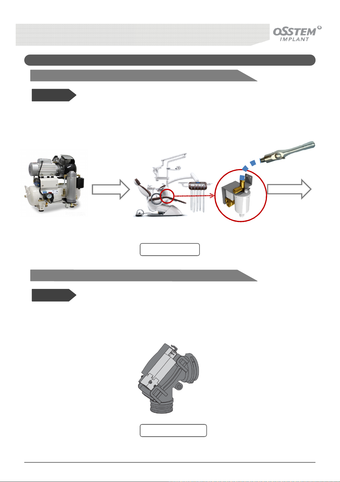
10-3. Other Options
10-3-1. Air Suction
Before Use!
• The Saliva Ejector is operated with only the pressure from the Air Compressor, without the use of a
Motor Suction. Pulling out the Saliva Ejector from the Instrument Holder of the Assistant’s Table powers
on the Air Suction.
Air in
Compressor
10-3-2. Suction Valve
Before Use!
• The Suction Valve improves Suction Pump efficiency and prevents residual infectious bacteria as well as
unpleasant odor by opening and closing the Membrane.
Unit-Chair
[Fig. 49] Air Suction
Air out
K3
UNIT CHAIR [OS-UM-C002 Ver.2]
[Fig. 50] Suction Valve
65
Page 66
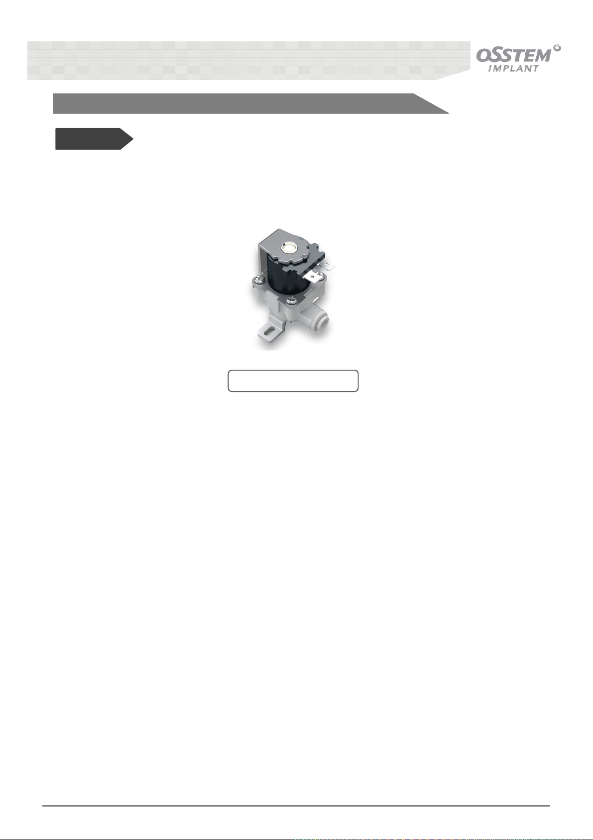
10-3-3. Main Water Sol. Valve
Before Use!
• The Main Water Sol. Valve switches tap water supply to the Unit and Chair ON/OFF. It acts as leakage
and backflow prevention, and automatically functions only when water is used at the Unit and Chair.
[Fig. 51] Water Sol. Valve
K3
UNIT CHAIR [OS-UM-C002 Ver.2]
66
Page 67
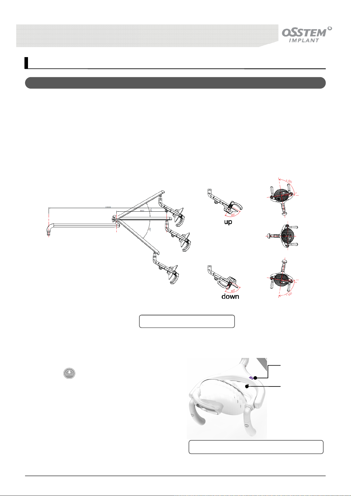
11. Dental Light - Option
11-1. Dental Light
• The Dental Light automatically switches on when the Chair move to a pre-determined position.
Brightness is controlled with the Brightness Control knob on the underside of the Light head.
• Power is Switched ON/OFF using the contactless sensor or the toggle switch.
• The head is free to rotate up, down left and right.
* Brightness is 0 ~ 45,000 Lux at light distance 600 ~ 800 mm.
[Fig. 52] Dental Light Operation
■ Dental Light ON/OFF Method
• Press button on the Dr. Table Panel to switch on
the Light.
• Can switch Light ON/OFF using contactless sensor.
• Can switch Light ON/OFF using toggle switch.
※ Should the user wish not to use the contactless
sensor request customer service to have the
function disabled at installation or any other time
henceforth.
K3
UNIT CHAIR [OS-UM-C002 Ver.2]
Contactless
Sensor
Toggle Switch
[Fig. 53] Dental Light Power Operating Method
67
Page 68
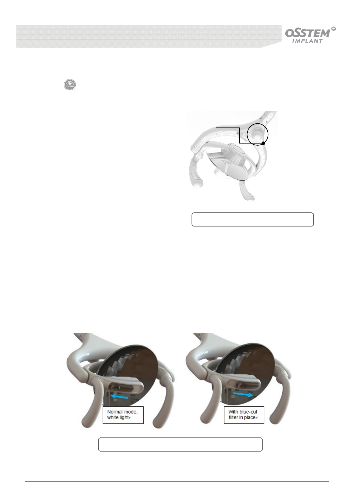
■ Dental Light Brightness Control Method
• Press button on the Dr. Table Panel to switch on the Light.
• Control brightness using the Brightness Control knob on the underside of the Light head.
Brightness control knob
• Turn the Brightness control knob located on
the underside of the Light head [Fig. 54]
clockwise to increase brightness, and anti-
clockwise to decrease brightness.
[Fig. 54] Light brightness control method
■ “Blue cut” feature
• The Lamp has a “blue cut” or “non-curing” feature. This feature is intended to reduce the intensity of
blue light wavelengths and therefore reduce premature curing of light-cured resins and
composites during dental procedures.
• The blue-cut feature is implemented using a yellow absorption filter which is manually moved into
position by the user as shown in [Fig. 55]
K3
UNIT CHAIR [OS-UM-C002 Ver.2]
[Fig. 55] Illustration of manual control for “blue-cut” filter
68
Page 69
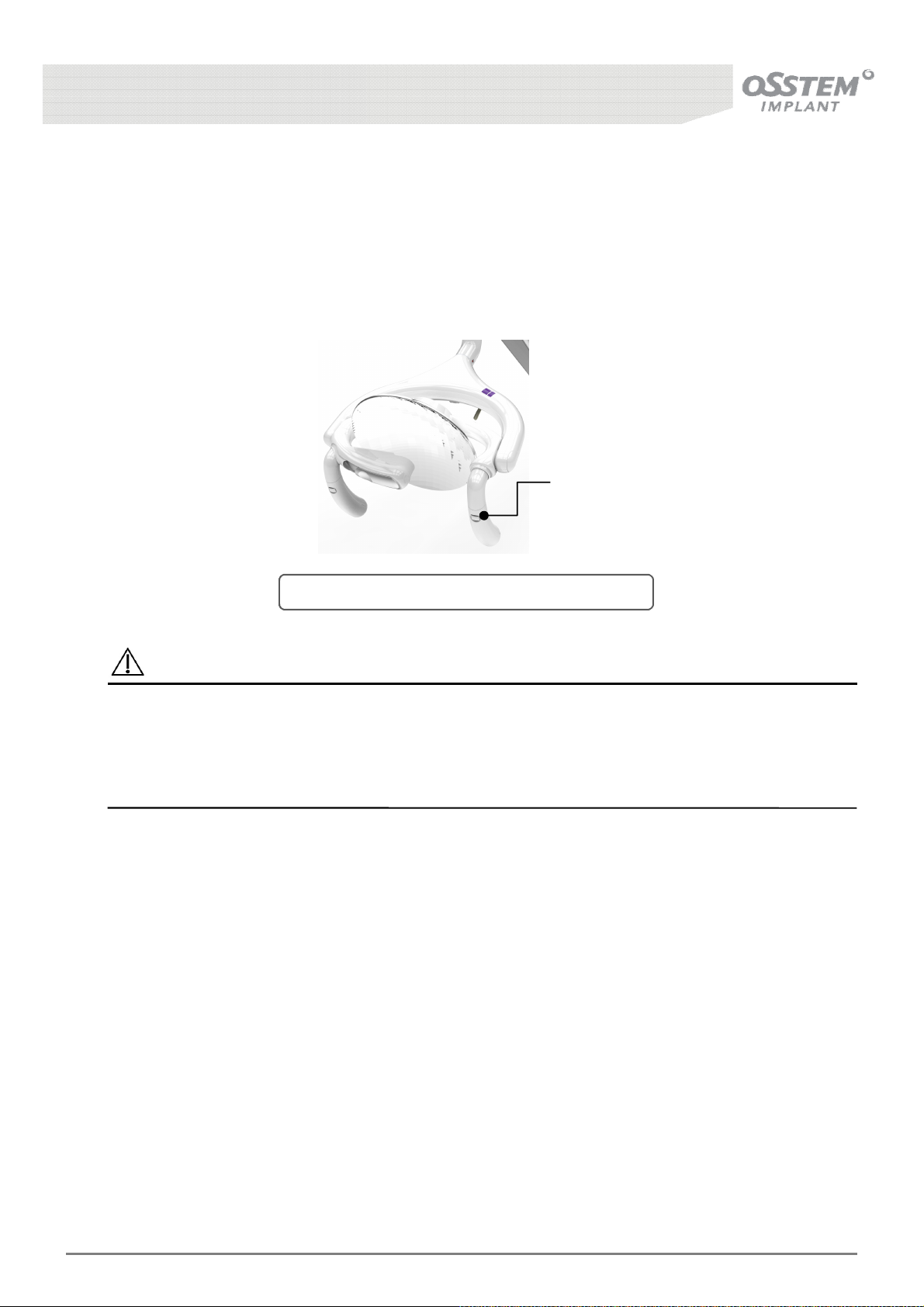
■ Handle detachment
• Press the button at the top of the handle with reasonable force.
• Pull the handle downward whilst pressing the button to detach the handle.
• The detached handle can be disinfected in an autoclave.
Handle Detachment
button
[Fig. 56] Dental Light handle detachment method
Caution
Do not use this equipment for purposes other than dental use.
All power cords must be completely and securely connected.
Area of radiation must be suitably adjusted for each treatment.
Disinfect the handle in an autoclave at 131℃ for more than 4 minutes.
K3
UNIT CHAIR [OS-UM-C002 Ver.2]
69
Page 70
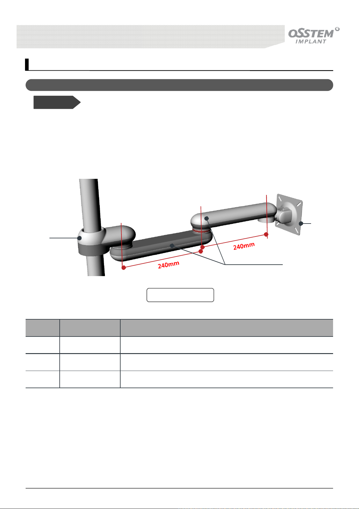
12. Other Accessories - Option
12-1. Monitor Arm
Before Use!
• This supports the monitor and fixes it to various positions as desired by the user.
• Osstem’s Monitor Arm is equipped with functions to adjust the rotational degree of rotating parts.
■ How to use
①
③
[Fig. 57] Monitor Arm
No. Name Function and Method of Operation
① Pole Arm Section mounted to the chair
② Main Arm Section of support and rotation of the monitor
③ Monitor Bracket Section on which the monitor is installed
②
K3
UNIT CHAIR [OS-UM-C002 Ver.2]
70
Page 71
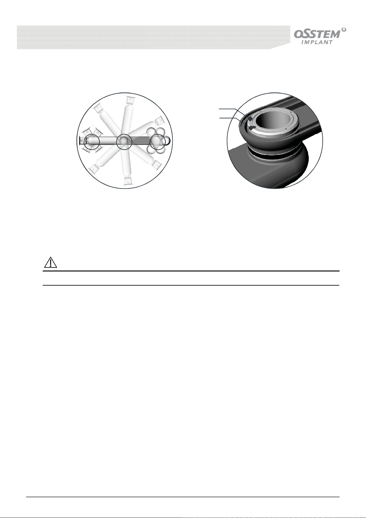
B
A
A
Rotates 300º at each
of the sections A, B, C.
B C
Loosen A (hexagonal
wrench bolt) and
tighten B (lock nut)
to control the degree
of rotation.
Caution
Suggested monitor size is < 22”, maximum size is 24” and < 4 kg.
K3
UNIT CHAIR [OS-UM-C002 Ver.2]
71
Page 72
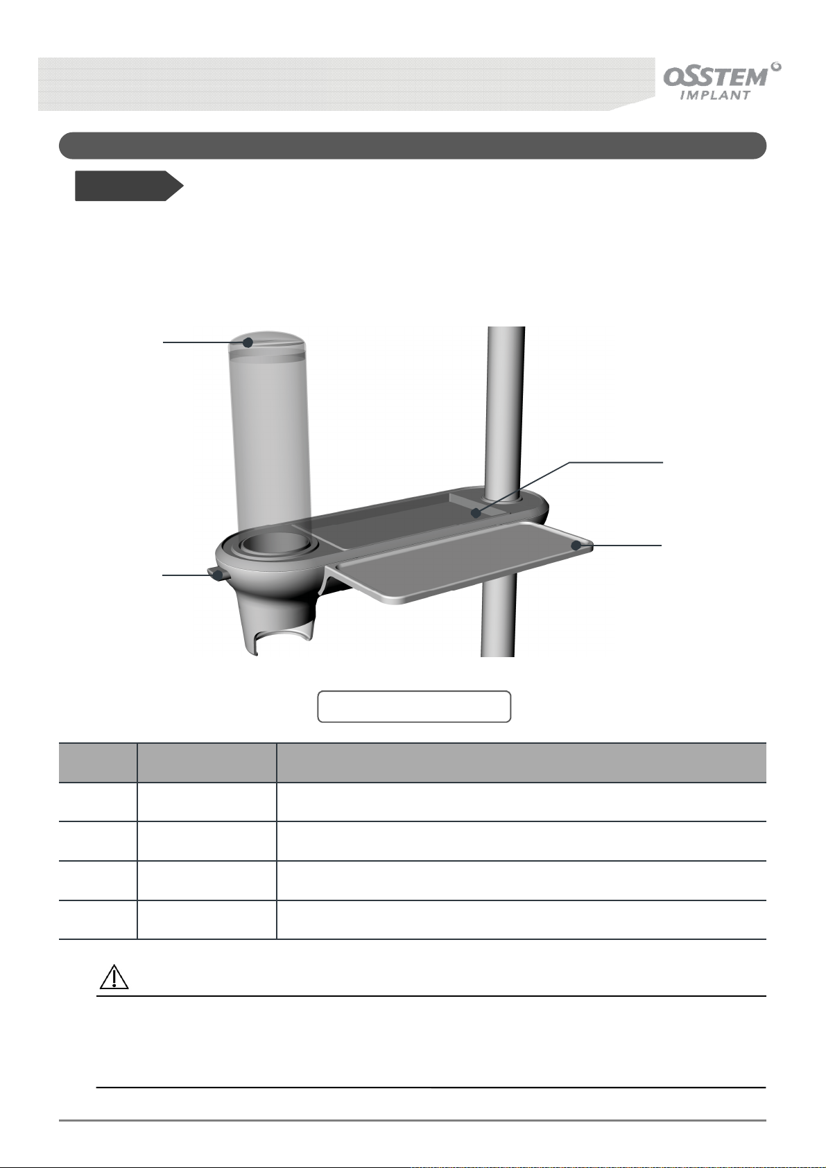
12-2. HANARO Console
Before Use!
• HANARO Console is an exclusive accessory for Unit Chair. It is equipped in the chair for
patient convenience and functions to dispenses cups, stores box tissues, hold personal
belongings, etc.
①
③
④
②
[Fig. 58] HANARO Console
No. Name Function and Operation Method
① Cup Holder CAP Cap through which a paper cup is inserted.
② Button Press the Button to pull out a paper cup
③ Tissue Holder Space for holding box tissues
④ Console Space where the patient’s belongings are placed
Caution
There is risk of product damage if load of over 1.5kg is applied to the console.
* For boxed tissue sold in the market, consider the tissue holder size. (Allowable size: Smaller
than height 116mm)
K3
UNIT CHAIR [OS-UM-C002 Ver.2]
72
Page 73
13. Cleaning and Maintenance
13-1. Barrier Protection
• Osstem recommends barrier protection for all applicable touch and transfer surfaces.
Touch surfaces are areas that come into contact with hands and become potential cross-contamination
points during dental procedures. Transfer surfaces are areas that come
into contact with instruments and other inanimate objects.
Barriers must be produced as the medical device regulations specific to your location.
Caution
If you use barriers, always replace the barrier film after each patient.
13-2. Upholstery
To preserve the quality of your Osstem upholstery, use barrier covers
instead of relying on chemicals. Barriers significantly extend the life of the upholstery and will
help to preserve its luxurious look and soft feel. To clean the upholstery, use a solution of mild detergent
and water. Use surface disinfectants only when the barriers have been compromised or if there is visible
spatter on the upholstery.
Caution
Minimize the use of surface disinfectants on the upholstery.
Chemicals can cause deterioration and shorten the life of upholstered surfaces.
Caution
• Disposal
- Any waste which is generated must be recycled or disposed of in strict compliance with all
applicable national regulations in a manner which is safe both for people and the environment.
• Disposal of electronic and electrical devices
- According to EC directive 2002/96 concerning used electrical and electronic devices, this product
is subject to the cited directive and must be disposed of accordingly within Europe.
K3
UNIT CHAIR [OS-UM-C002 Ver.2]
73
Page 74
13-3. Cleaning the Unit
• Use a solution of mild, non-ionic detergent and water, or commercially available cleaners
containing no alcohol, bleach, or ammonia. Dishwashing detergent is usually non-ionic.
Because the hardness of water varies from locale to locale, you should experiment to
determine the best mix of detergent to water. Mix just enough detergent to allow for good
cleaning without leaving a soapy film on the surface. Never use abrasive cleansers,
scrubbing pads, or other abrasive applicators because they can permanently scratch or otherwise
damage equipment surfaces. Be careful using recycled paper products, such as paper
towels, that may be abrasive.
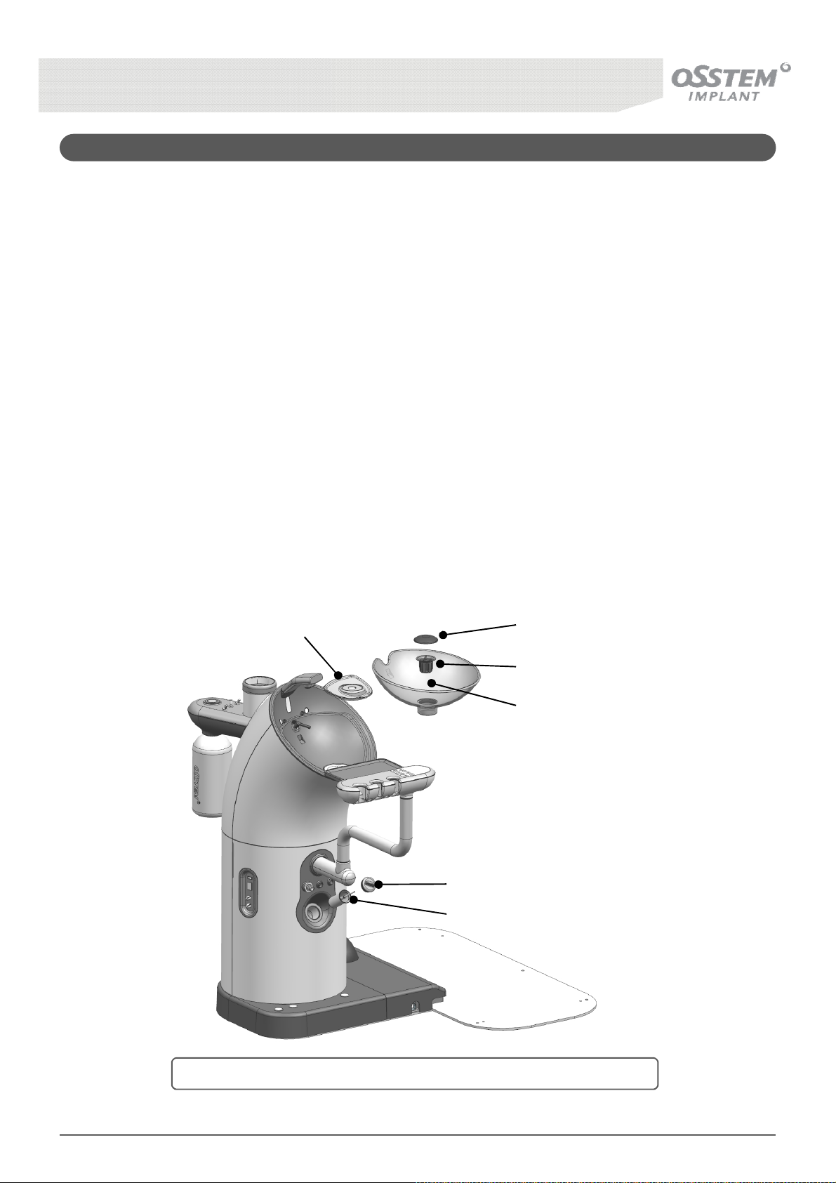
• The Spittoon and Spittoon Filter should be detached and cleansed once a day. As for the
cleaning method, separate the Cup Holder from the water cleaning pipe, detach the Spittoon, lift the
Spittoon Filter Stopper, first, and then take out the Spittoon Filter, and remove solid
waste and cleanse the Spittoon.
• After many uses, suctioning capacity may be compromised when suction filter is blocked
with solid waste. Thus, waste must be removed once every two days by taking out the filter
stopper. To clean take out the stopper from filter and remove waste from the net.
Cup Holder Spittoon Filter Stopper
Spittoon Filter
Spittoon
Suction Filter Stopper
Suction Filter
[Fig. 59] How to clean the Spittoon and Absorption Filter (Suction Filter)
K3
UNIT CHAIR [OS-UM-C002 Ver.2]
74
Page 75
13-4. Cleaning the 3-Way Syringe
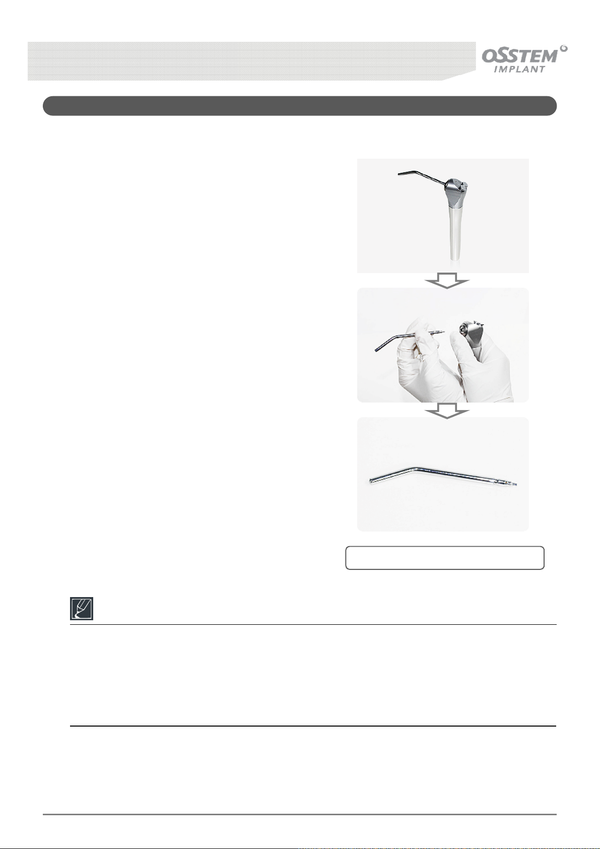
■ Method of Cleaning
To disconnect the nozzle from the 3-Way Syringe,
press down on the nozzle connection point and
pull the nozzle out.
Disinfect the disconnected nozzle in an
Autoclave at 132°C for more than 7 minutes.
Additionally, to clean the 3-Way Syringe, use a
solution of mild detergent and water. Use surface
disinfectants only when the barriers have been
compromised or if there is visible spatter on the
3-Way Syringe
Reference
The 3-Way syringe Nozzle provided by Osstem is not sterilized.
Before using for the first time, sterilize according to the information below.
- Sterilization type : Gravity
- Exposure time : 132˚C, 7min
- Dry time : 15min
K3
UNIT CHAIR [OS-UM-C002 Ver.2]
[Fig. 60] How to clean the 3-Way syringe
75
Page 76
13-5. Saliva Ejector
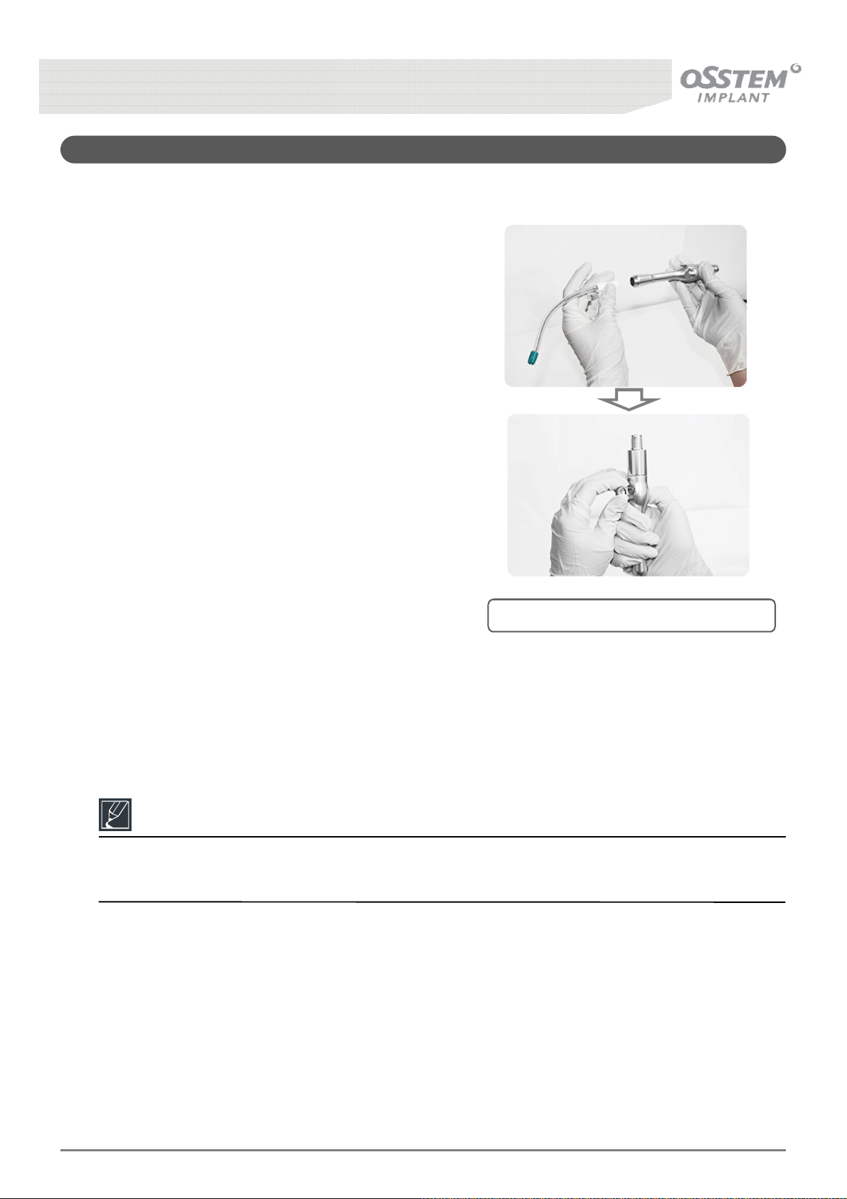
■ Cleaning Method
• The nozzle of the saliva ejector disconnects when
pulled forward (the nozzle is not provided)
• The lever of the saliva ejector disconnects when
the back of the lever is pressed [Fig. 61].
• To clean the Vacuum Valves, use a solution of mild
detergent and water. Use surface disinfectants only
when the barriers have been compromised or if
there is visible spatter on the Vacuum Valves.
Reference
•Osstem does not provide the Vacuum Valves Nozzle.
- Clean according to the manufacturer information
[Fig. 61] How to clean the Saliva Ejector
K3
UNIT CHAIR [OS-UM-C002 Ver.2]
76
Page 77

13-6. Water System Cleaning and Maintenance
(For example: Robert Koch Institute (RKI), American Dental Association (ADA), Center for
• The following is Osstem’s recommended procedure for dental unit waterline cleaning and maintenance
* Step 1 : Add Waterline Cleaner
① Turn dental unit OFF.
② Turn OFF water supply of the dental unit.
③ Pour adequate amount of Waterline Cleaner into Portable Dental Waterline Cleaning System.
④ Connect Portable Dental Waterline Cleaning System to Main Waterline of Dental Unit.
⑤ Remove Hand-piece, Scaler etc. from the hose.
⑥ Turn dental unit ON. Activate Hand-piece hoses and air/water syringes until Waterline Cleaner exits.
⑦ Turn dental unit OFF. Allow Waterline Cleaner to treat waterlines at least 12 hours before proceeding
to Step 2.
* Step 2 : Flush dental unit waterlines
① Remove Portable Dental Waterline Cleaning System, dispose of any excess Waterline Cleaner and turn
ON water supply of the dental unit.
② Turn dental unit ON. Flush waterlines with water for adequate time to remove any excess Waterline
Cleaner.
Reference
• Osstem does not provide the Portable Dental Waterline Cleaning System.
• Osstem does not provide the Waterline Cleaner.
- National requirements and guidelines regarding hygiene and disinfection should be followed.
Disease Control (CDC))
K3
UNIT CHAIR [OS-UM-C002 Ver.2]
77
Page 78
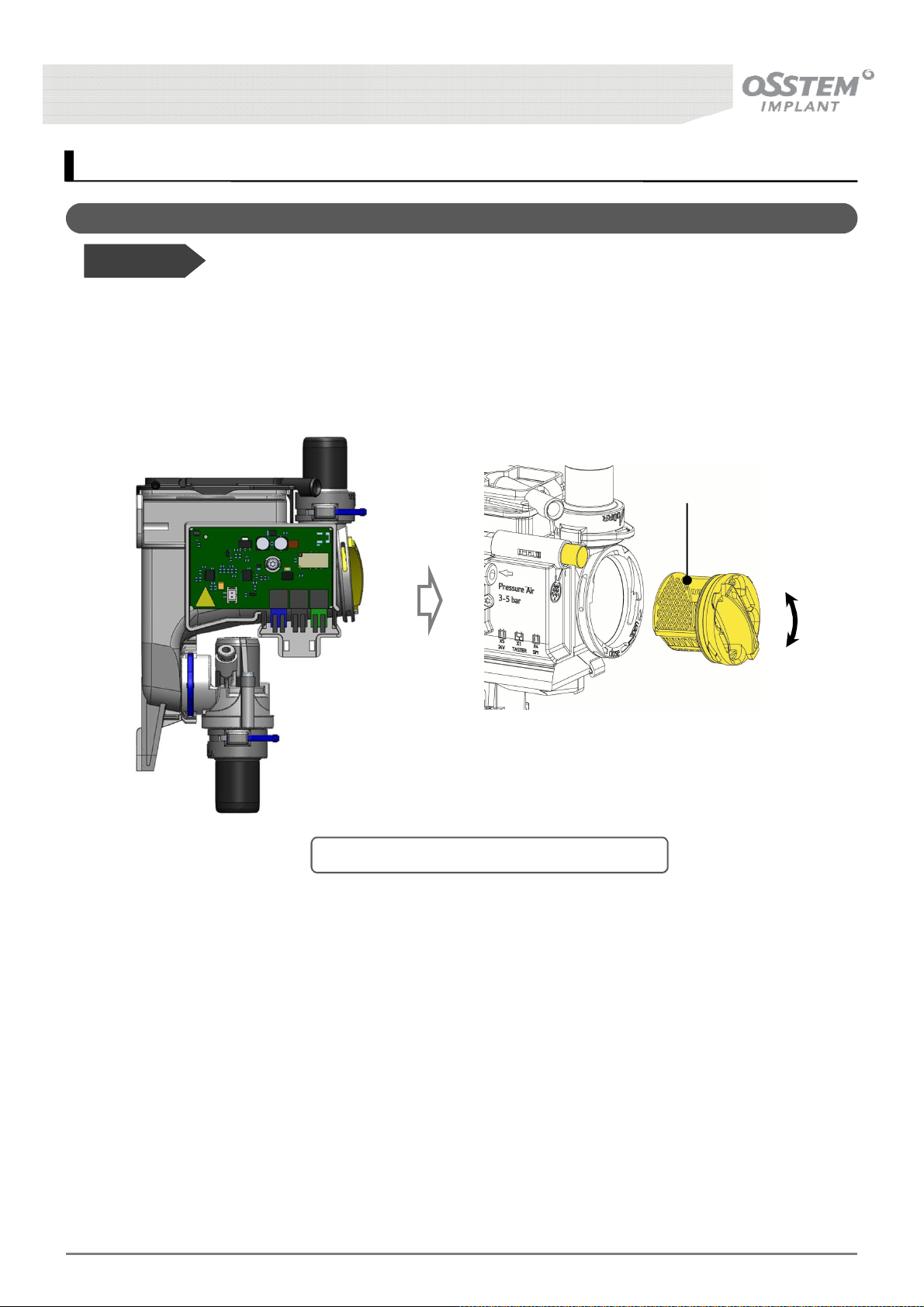
14. Cleaning and Maintenance - Option
14-1. Cleaning the Spittoon Valve
Before Use!
• Only applies to Unit Chairs containing Spittoon valves.
• The Spittoon Valve prevents backflow of residual infectious bacteria as well as unpleasant odor from the
wastewater lines by automatically opening when water is used at the spittoon.
Spittoon Valve Filter
Open
[Fig. 62] How to clean the Spittoon Valve filter
■ Cleaning Method
① Turn dental unit OFF
② Unit Cover Disassembly
③ Unit Main PCB board frame open
④ Rotate Spittoon Valve Filter Cover anti-clockwise
⑤ Remove filter to remove filth and clean, then re-install
Close
K3
UNIT CHAIR [OS-UM-C002 Ver.2]
78
Page 79
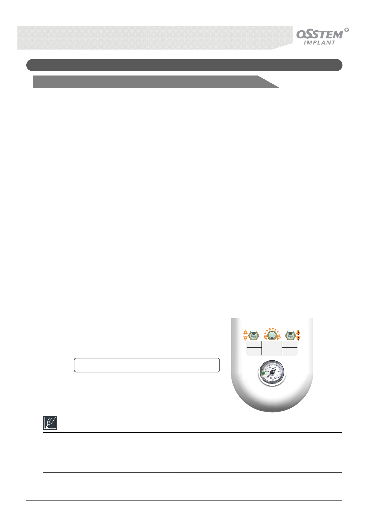
14-2. Water System Cleaning and Maintenance
14-2-1. Bottled Water System Type – City Water
• The following is Osstem’s recommended procedure for dental unit waterline cleaning and maintenance
* Step 1 : Add Waterline Cleaner
① Check water bottle and water supply toggle switches (Water Supply: CITY, Water Bottle: OFF)
② Detach the Bottle from the Unit and fill it with 1.2L of Waterline Cleaner, then re-install.
③ Set the toggle switches to Bottle for Water Supply, and ON for Water Bottle. Check air injection into
the bottle and set air pressure to 1.5 ~ 2.0 bar.
④ Remove Hand-piece, Scaler etc. from the hose.
⑤ Activate Hand-piece hoses and air/water syringes until Waterline Cleaner exits.
⑥ Set the toggle switches to City for Water Supply, and OFF for Water Bottle.
⑦ Turn dental unit OFF. Allow Waterline Cleaner to treat waterlines at least 12 hours before proceeding
to Step 2.
* Step 2 : Flush dental unit waterlines
① Turn dental unit ON. Flush waterlines with water for adequate time to remove any excess Waterline
Cleaner.
② Detach the spittoon and bottle to clean.
CITY ON
WATER
BOTTLE
WATER
SUPPLY
BOTTLE
PRESSURE
CONTROL
OFF
WATER
BOTTLE
[Fig. 63] Switch between tap and distilled water
Reference
Check toggle switch direction when detaching the water bottle.
- Water Supply : City
- Water Bottle : OFF
K3
UNIT CHAIR [OS-UM-C002 Ver.2]
79
Page 80

14-2-2. Water Bottle System Type – Only Distilled Water
• The following is Osstem’s recommended procedure for dental unit waterline cleaning and maintenance
* Step 1 : Add Waterline Cleaner
① Check water bottle and water supply toggle switches (Water Supply: CITY, Water Bottle: OFF)
② Detach the Bottle from the Unit and fill it with 1.2L of Waterline Cleaner, then re-install.
③ Set the toggle switches to Bottle for Water Supply, and ON for Water Bottle. Check air injection into
the bottle and set air pressure to 1.5 ~ 2.0 bar.
④ Remove Hand-piece, Scaler etc. from the hose.
⑤ Activate Hand-piece hoses and air/water syringes until Waterline Cleaner exits.
⑥ Set the toggle switches to City for Water Supply, and OFF for Water Bottle.
⑦ Turn dental unit OFF. Allow Waterline Cleaner to treat waterlines at least 12 hours before proceeding
to Step 2.
* Step 2 : Flush dental unit waterlines
① Detach water bottle, clean, fill with distilled water then re-install.
② Turn dental unit ON. Set toggle switches to Bottle for Water Supply, and ON for Water Bottle. Check
air injection into the bottle and set air pressure to 1.5 ~ 2.0 bar.
③ Flush waterlines with water for adequate time to remove any excess Waterline Cleaner.
② Detach spittoon and bottle to clean.
K3
UNIT CHAIR [OS-UM-C002 Ver.2]
80
Page 81

14-2-3. Waterline Cleaning System Type
• The following is Osstem’s recommended procedure for dental unit waterline cleaning and maintenance
* Step 1 : Add Waterline Cleaner
① Add Cleaner
- Detach bottle from the unit, fill with 1.2L of Waterline Cleaner, then re-install.
② Waterline Cleaning System toggle switch setting
- Set the toggle switches to Bottle for Water Supply, and On for Water Bottle. Check air injection into
the Bottle and set air pressure to 1.5 ~ 2.0 bar
③ Waterline Cleaning Mode
- Press F&Water buttons on the Doctor’s Table Panel together to enter Waterline Cleaning Mode.
④ Holder / HP Placement
- Install the Waterline Cleaning Holder on the Spittoon, and insert the hoses (Syringe, Hand-piece etc.)
into the Holder.
[Warning: detach equipment (Syringe, hand-piece etc.) and insert just the hoses]
⑤ Cleaning Method Selection/Begin Chemical Cleaning
- Press (-) button on the Doctor’s Table Panel to select Chemical Cleaning; cleaning begins immediately
upon selection and proceeds for a duration of 7 minutes.
⑥ Complete Chemical Cleaning
- Upon completion of chemical cleaning the phrase "Chemical Clean End HP" appears on the LCD, and
a melody rings. Once the melody rings set the toggle switches to Bottle for Water Supply, and OFF
for Water Bottle. Turn the main power switches off and leave for 12 hours.
* Step 2 : Flush dental unit waterlines
① Waterline Cleaning Mode
- Switch main power On. Press F & Water buttons on the Doctor’s Table Panel together to enter
Waterline Cleaning Mode.
② Waterline toggle switch settings
- Set waterline toggle switches to City for Water Supply, and Off for Water Bottle.
③ Cleaning Method Selection/Begin Water Cleaning
- Press (+) button on the Doctor’s Table Panel to select Water Cleaning; cleaning begins immediately
upon selection and proceeds for a duration of 10 minutes.
K3
UNIT CHAIR [OS-UM-C002 Ver.2]
81
Page 82
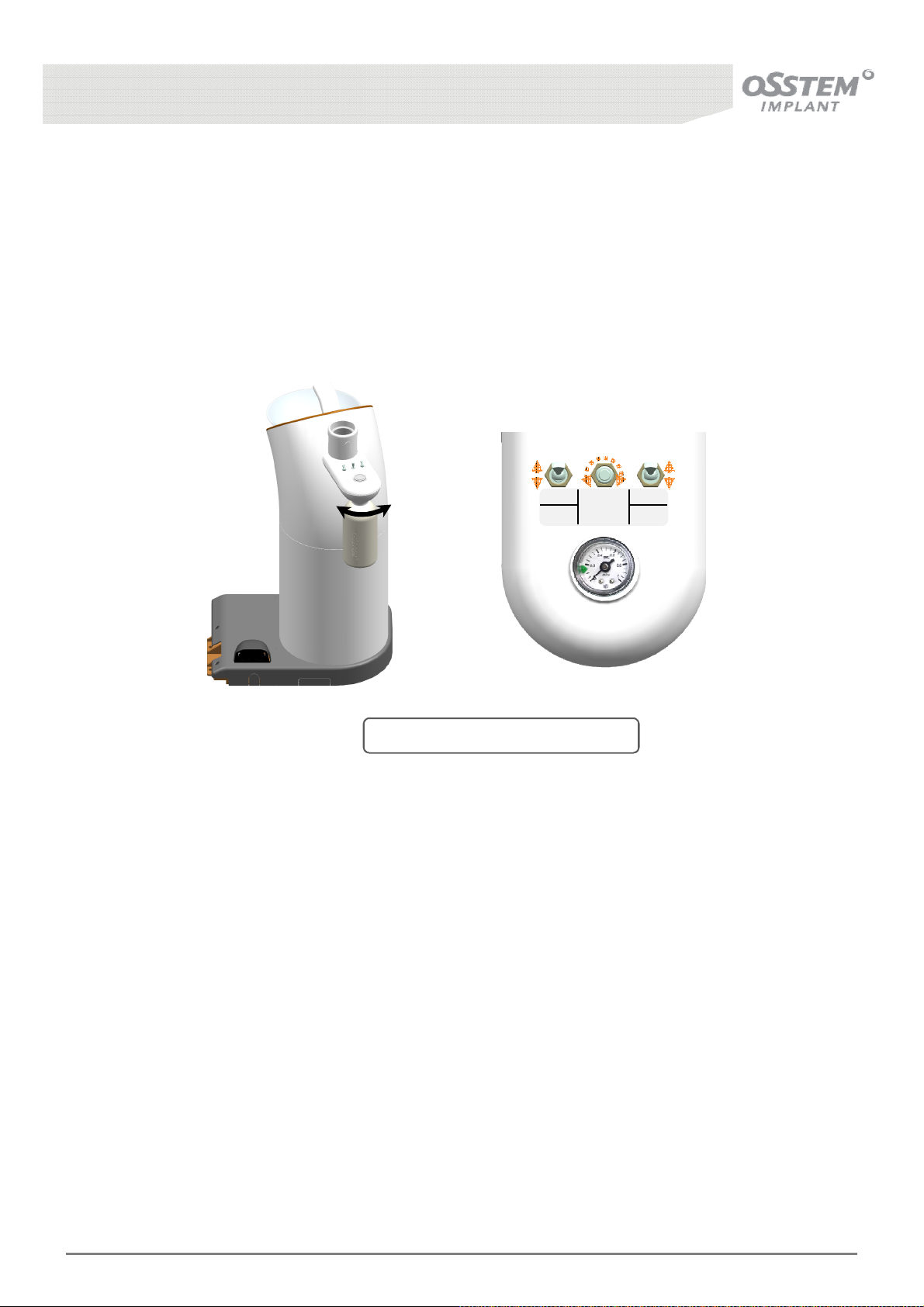
④ Complete Water Cleaning
- Upon completion of water cleaning the phrase “Remove the holder and HP" appears on the LCD, and
a melody rings. Once the melody rings return the hoses from the Waterline Holder to the original
position, and press the Water Cleaning button to complete Waterline Cleaning.
⑤ Cleaning
- Rinse and clean the Waterline Holder / Bottle / Spittoon
CITY ON
WATER
BOTTLE
CloseOpen
WATER
SUPPLY
BOTTLE
PRESSURE
CONTROL
OFF
WATER
BOTTLE
[Fig. 64] Waterline Cleaning System
K3
UNIT CHAIR [OS-UM-C002 Ver.2]
82
Page 83
15. How to store and maintain after use
1) Set the chair for treatment to the initial status using the Button.
2) Turn OFF power of the dental unit.( 23)
3) Please sterilize and store used Hand-piece and Scaler in according with the manual of
purchased product
4) Cleanse foreign substances on the Spittoon Base and let water flow into the drain to
cleanse.( 76)
5) Inject enough water from the to allow the drainer or air vacuum, to cleanse the inside of the
piping.
6) To sterilize each part of the treatment device, wet a cotton ball with ethanol or
benzalkonium chloride to cleanse the surface.
7) Unplug the power code when you will not use it for a long time.
8) Wipe each part and the seat of the chair using detergent and dry cloth.
9) Conduct regular repair check and maintenance.
Method Part Frequency
Auto-clave sterilization treatment device Frequently
Rub each part and the seat Frequently
Cleansing
Spittoon and Spittoon Filter once a day
Check Oil injection once a year
K3
UNIT CHAIR [OS-UM-C002 Ver.2]
Suction Filter once in two days
83
Page 84
16. Troubleshooting
Trouble How to resolve
- Make sure the power cord is plugged into an outlet properly.
(AC 100-120/220-240V)
Chair won’t work.
H.P. won’t work.
Low H.P. won’t work.
- Make sure the main switch is turned on.
- Check for any fuse abnormality.
(Disconnection in fuse can be checked visually)
- Make sure the foot controller is not pressed. (Safety switch operation)
- Ensure the proper inflow of air pressure.
(40psi or 2.5 - 3㎏/㎠)
- Check the gauges in the table’s lower part.
- Oil injection should be thoroughly checked. (Once a day as a rule)
- Make sure that each HP is put in place. (Not working at the same time)
- Ensure the proper inflow of air pressure.
(40psi or 2.5 - 3㎏/㎠)
- Check if the rotation control switch on the body is placed on F or R.
(Does not operate if switch is placed on the center)
- Make sure that the wet/dry switch is turned on.
Water won’t run from H.P.
Scaler won’t work.
K3
UNIT CHAIR [OS-UM-C002 Ver.2]
- Make sure that the supply control valve on the lower part of the doctor’s tabl
e is open.
- Make sure the tubing is not clogged. (Check after removing the H.P. body.)
- Remove the tubing of the supply control valve and blow with a syringe.
- Water supply is OK but no vibration.
Is the tip loosened?
(If the tip is loose, power is not supplied.)
Check the power control volume.
- It vibrates, but water won’t run.
Check if the WET/DRY switch is turned on.
Check the supply control valve at the lower part of the Doctor’s Table.
Is the tubing clogged? (Check by removing the Scaler body.)
(Remove the tubing of the supply control valve and blow with a syringe.)
84
Page 85
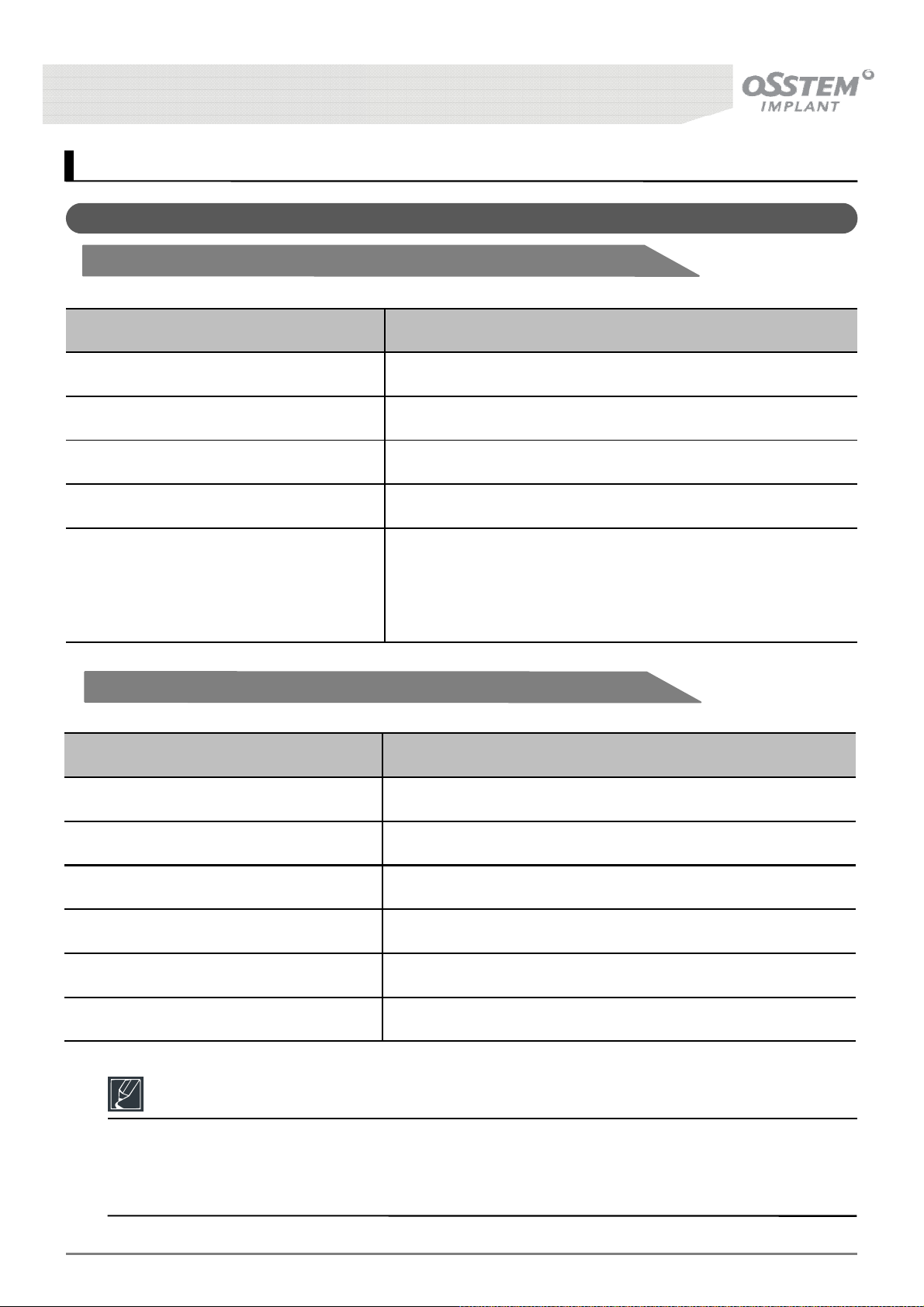
17. Product Specifications
17-1. Product Specifications
17-1-1. Electrical system
Item Details
Input Voltage AC 100-120 / 220-240V
Frequency 50/60Hz
Power Consumption 1.2kVA
Customer-provided fuse protection Automat C 16 or screw-plug fuse 10A
Class I
Classification
IPX0(Dental Chair and Unit)
17-1-2. Water supply
Item Details
Water quality Tap water
Water pressure limits 2.0 to 6.0 bar
Water rated flow rating 3l/min
Water hardness 1.5 to 2.14 mmol/l ≤ 8.4 to 12º dH
pH 6.5 to 8.0
Particle filter Filterability : 90㎛
B type
IPX1(Foot Controller)
Reference
• If the water is very hard (above 12 dH), a water softening device must be fitted in the ion-
exchange process.
• Insufficient water hardness (below 8.4 dH) can promote the formation of algae.
K3
UNIT CHAIR [OS-UM-C002 Ver.2]
85
Page 86
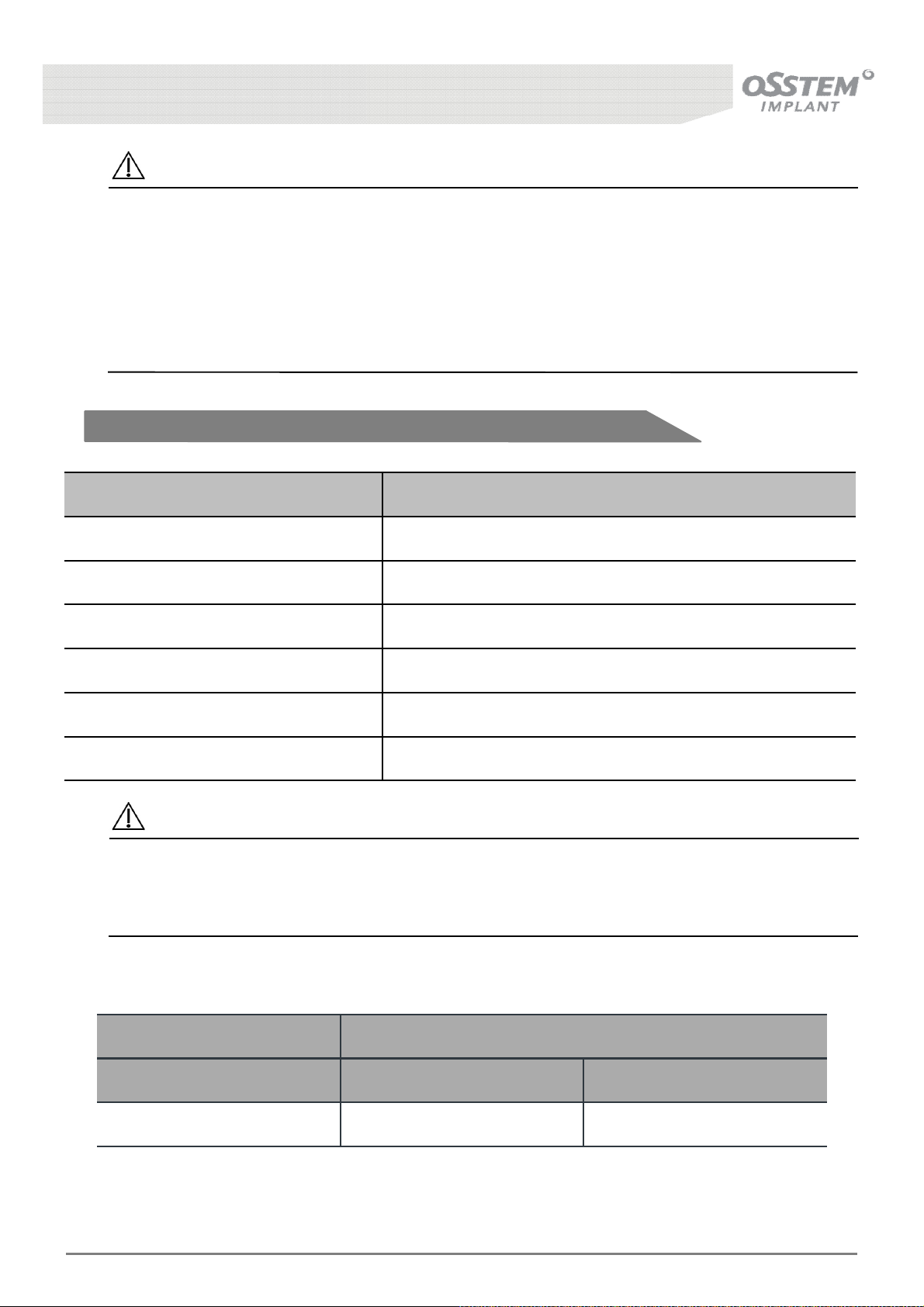
Caution
• Danger of infection if the national guidelines are not observed.
• Contamination of the treatment water or the drinking water network.
- Observe and adhere to the national guidelines concerning the quality of water for human
consumption (potable water) – if available.
- Observe and adhere to the national guidelines concerning the prevent of reflux (flow of water
from the treatment unit to the public water network) – if relevant.
17-1-3. Air supply
Item Details
Air rated Max. pressure 7.5 bar
Water rated flow rating 50Nl/min
Particle filter Filterability : 5㎛
Solids filter for suction system Filterability : 2mm
pH 6.5 to 8.0
Particle filter 5㎛
Caution
• Danger of infection due to non-adherence to the national guidelines concerning the quality of
dental air.
- Observe and adhere to national guidelines concerning the quality of dental air – if available.
* Suction
Suction vacuum at device intake
Suction air quantity at spray
mist cannula
with wet suction
with dry suction
minimal V~250 Nl/min X > 85 mbar
K3
UNIT CHAIR [OS-UM-C002 Ver.2]
86
Page 87
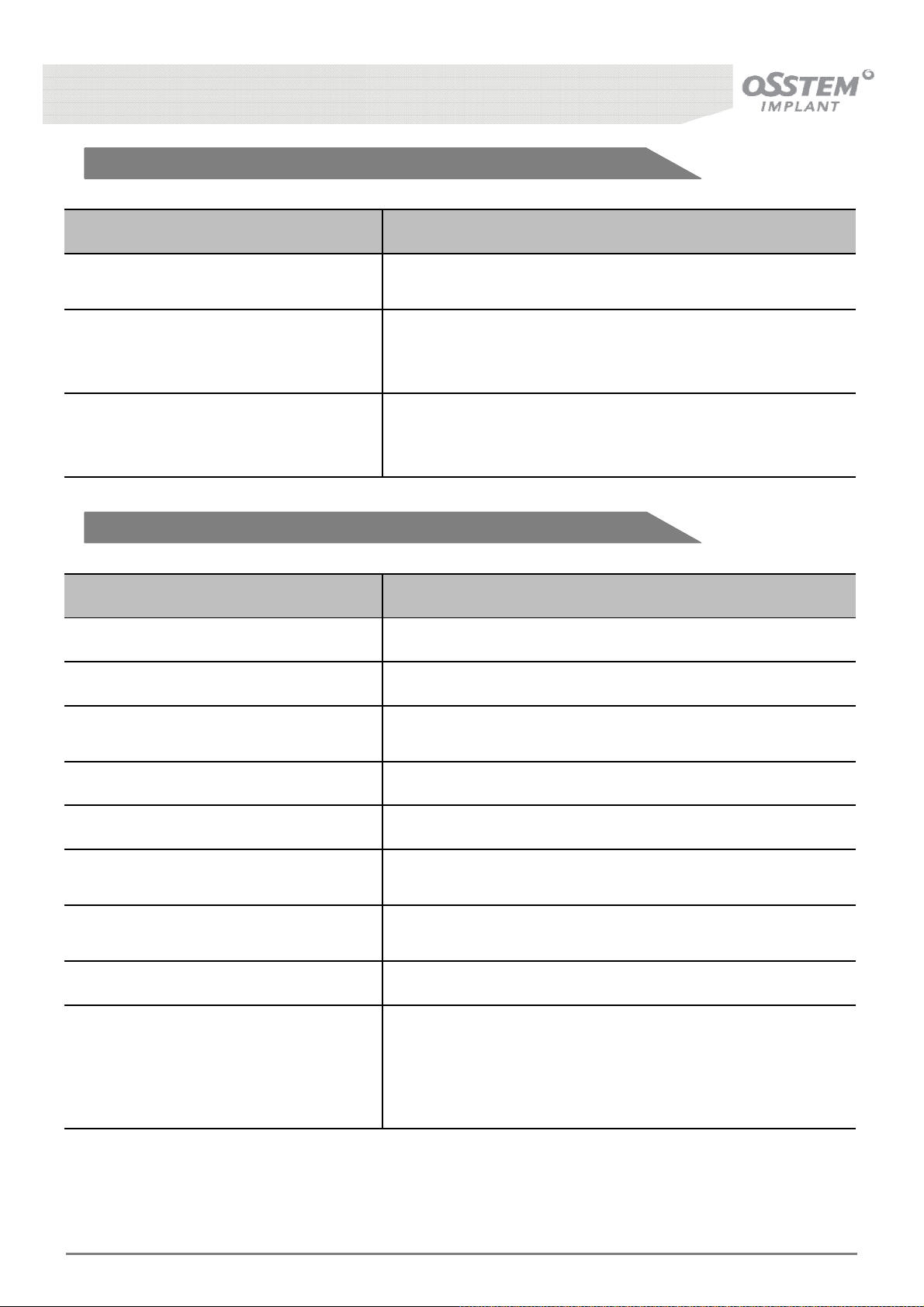
17-1-4. Environment
Item Details
Atmospheric pressure
Relative Humidity
Ambient Temperature
17-1-5. Weight
Item Details
Weight 318 kg
Lift Method Hydraulic electromotor
Operation : 700 ~ 1060 hPa
Storage/Ship : 500 ~ 1060 hPa
Operation : 30 ~ 75 %RH
Storage : 10 ~ 90 %RH
Ship : 30 ~ 85 %RH
Operation : 10 ~ 35 ℃
Storage : -10 ~ 35 ℃
Ship : 38 ~ 60 ℃
Chair Height
Chair Length 1,800 mm
Mass of Patient 135 kg
Back Rest
Head Rest
Chair Duty Cycle ON: 60s, OFF:600s
Applicable Standards
IEC 60601-1-6 (2010) + AMD 1 (2013)
Max.: 735±10mm
Min.: 365±10mm
Max.: 63±5°
Min.: 1±5°
Max.: 45°
Min.: -10°
EN 60601-1, EN 60601-1-2
IEC 60601-1,
IEC 80601-2-60 (2012)
K3
UNIT CHAIR [OS-UM-C002 Ver.2]
87
Page 88
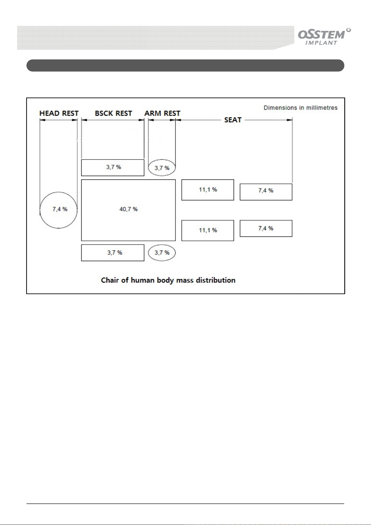
17-2. Chair of Human Body Mass Distribution
K3
UNIT CHAIR [OS-UM-C002 Ver.2]
88
Page 89
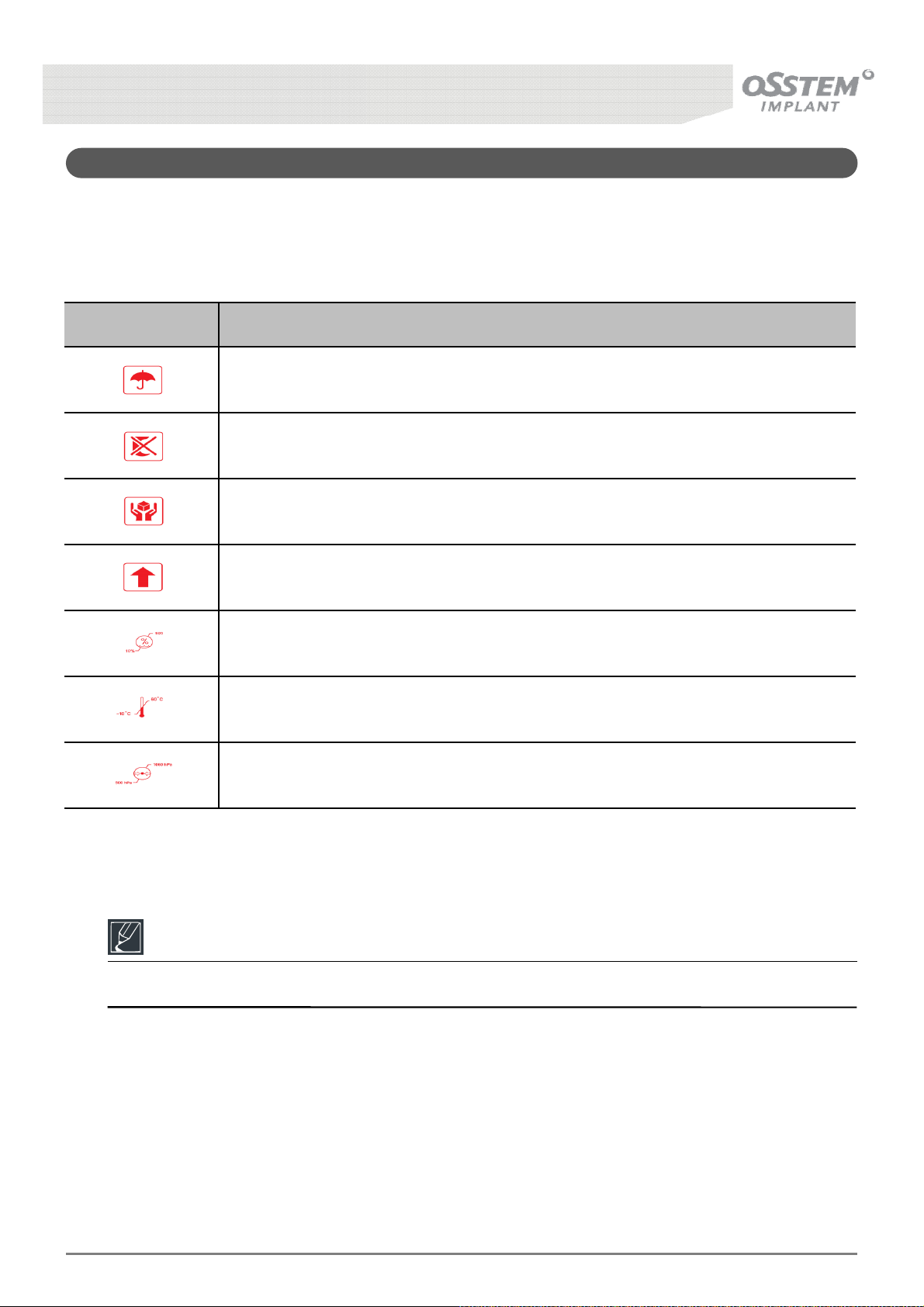
17-3. Information on the packaging : Storage and transportation
The symbols printed on the outside are for transportation and storage, and have the following
meaning
Symbol Function
Keep
Use no hook
Fragile
This Side up
Humidity
Temperature range
Air pressure
Reference
• Please keep the packaging in case you need to return the product for servicing or repair.
K3
UNIT CHAIR [OS-UM-C002 Ver.2]
89
Page 90
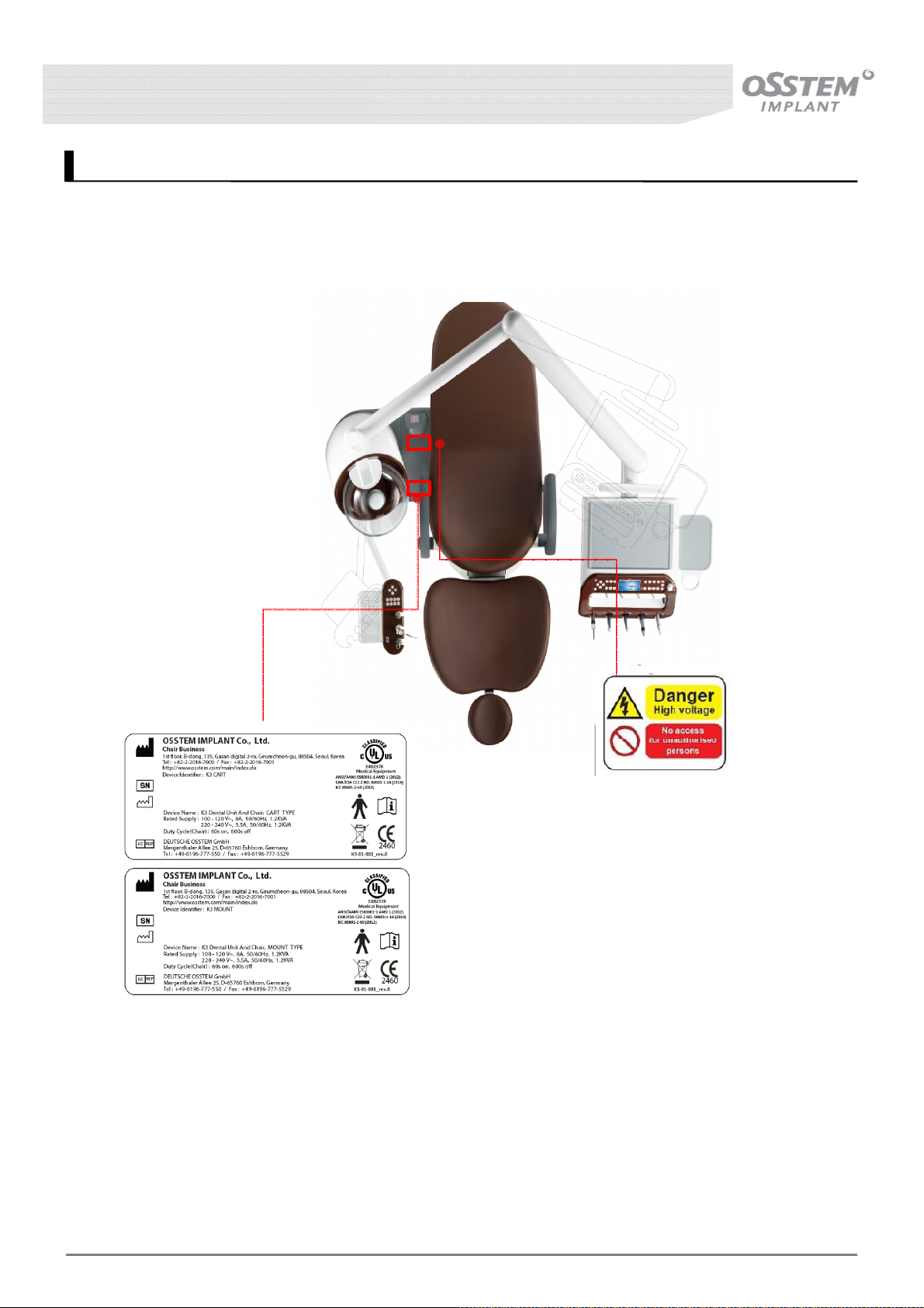
18. Product Indications
This is a product used for dental examination and treatment; the following are the product
indications:
• Marking may vary by country.
K3
UNIT CHAIR [OS-UM-C002 Ver.2]
90
Page 91
19. Warranty
19-1. Scope
• Osstem warrants all goods listed below against defects in material or workmanship under normal
intended use when purchased from Osstem or an authorized Osstem dealer. Osstem’s sole obligation
under the warranty is to provide parts for the repair, or replacement of any defective component with
one that is equivalent to the original in performance.
• This warranty is in lieu of all other warranties or obligations express or implied. Osstem expressly
disclaims all implied warranties of merchantability or fitness for a particular purpose. In no event will
Osstem be liable for indirect, special, incidental, exemplary, or consequential damages of any kind.
• The repair or replacement of components is contingent upon Osstem’s styles and color options available
at the time of the warranty claim. If a warranty claim is filed after a product or color has been
discontinued, Osstem reserves the right to honor the warranty in one of the following ways:
I. Replace the affected component with a new component in the same style and/or color.
II. Replace the affected component, and other product components in the operatory with a product
style and/or color similar to the originally purchased style and/or color.
• The buyer shall have no other remedy. The warranties set forth herein provide specific legal rights.
Additional rights may exist, based on the jurisdiction of purchase and use of the product to the extent
that those rights apply to this agreement.
• Warranty exclusions are identified in section 19-3.
• Written notice of product failure must be given to Osstem within the warranty period.
19-2. Period
• The period of warranty is 2 years from the date of delivery for all products and parts hitherto mentioned
• Components replaced under warranty or purchased retain the balance of the original product warranty
or are warranted for 1 year after delivery (whichever is greater).
19-3. Exclusions
The warranty does not cover:
I. Damage resulting from improper maintenance, maintenance, or alterations.
II. Damage resulting from unwarranted movement of equipment installation site, accident, or freight
damage.
III. Damage resulting from use of parts and consumables other than those provided by Osstem.
IV. Damage resulting from natural disasters such as, but not limited to, fire, salt damage, flood,
earthquake, lightning and mains voltage failure.
V. Normal service items such as (but not limited to): light shields, light bulbs, filters, O-rings,
handpiece tubing, and water cartridges.
VI. Natural wear and tear
VII. All other products, not manufactured by Osstem, including OEM, follow the original manufacturer’s
warranty, and are not covered by Osstem’s warranty. Examples include, but not limited to:
sterilizers, maintenance equipment, cameras, curing lights, ultrasonics, control modules, electric
motors, attachments, handpieces, and turbines.
※ Failure to follow Osstem’s Instructions for Use will void the warranty
K3
UNIT CHAIR [OS-UM-C002 Ver.2]
91
Page 92
20. Contact Information
Manufacturer : OSSTEM IMPLANT Co., Ltd.
Address :1stfloor, B-dong, 135, Gasan digital 2-ro, Geumcheon-gu, 08504, Seoul, Korea
Tel : +82-70-4394-5157
Fax : +82-70-4394-5280
EU Representative : DEUTSCHE OSSTEM GmbH
Address : Mergenthaler Allee 25, D-65760 Eschborn, Germany
Tel : +49-6196-770-550
Fax : +49-6196-777-5529
K3
UNIT CHAIR [OS-UM-C002 Ver.2]
92
 Loading...