

OSSIA NVR5 User Manual
1
1

Notes
Please read this user manual carefully to ensure that you use the device correctly and
safely.
There may be incorrect info or printing errors in this manual. Updates and corrections will
be made into the future versions of this manual. The content of this manual is subject to change
without notice.
The device should be operated using only the type of power source indicated on the
marking label. The power voltage must be verified before use.
Do not install this device near any heat sources such as radiators, heat registers, stoves or
other devices that produce heat.
Do not install this device near water.
Clean only with a dry cloth.
Do not block any ventilation openings and ensure proper ventilation around the device.
Perform a safe power off before disconnecting from power.
This device is for indoor use only. Do not expose it to rainy or moist environments. In case
any solid or liquid get inside the device’s case, turn off the device immediately and get it
checked by a qualified technician.
Do not try to repair the device by yourself without technical aid or approval.
When this device is in use, the relevant contents of Microsoft, Apple and Google may be
shown. The ownerships of trademarks, logos and other intellectual properties related to
Microsoft, Apple and Google shall belong to the above-mentioned companies.
This manual is suitable for all NVR/DVR models running Ossia OS. Clear markings will
be made if some models do not support any of the features. All examples and pictures used in
the manual are from one of the models for reference purpose.
For devices with internal power supply, please make sure that the AC 220/110V input
selector is set correctly

Basic Operation Guide
User Manual
2
Contents
Contents ..................................................................................................................................... 2
1 Introduction ................................................................................................................... 6
1.1 Summary ....................................................................................................................... 6
1.2 Features ......................................................................................................................... 6
1.3 Front Panel Descriptions ............................................................................................... 9
1.4 Rear Panel Descriptions .............................................................................................. 10
1.5 Connections ................................................................................................................. 12
2 Basic Operations Guide .............................................................................................. 14
2.1 Startup & Shutdown .................................................................................................... 14
2.1.1 Startup .............................................................................................................. 14
2.1.2 Shutdown.......................................................................................................... 14
2.2 Remote Controller ....................................................................................................... 15
2.3 Mouse Control ............................................................................................................. 16
2.4 Text-input Instruction .................................................................................................. 16
2.5 Other Button Operations ............................................................................................. 16
3 Wizard & Main Interface ........................................................................................... 17
3.1 Startup Wizard ............................................................................................................. 17
3.2 Main Interface ............................................................................................................. 24
3.2.1 Main Interface Introduction .............................................................................. 24
3.2.2 Setup Panel ....................................................................................................... 26
3.2.3 Main Functions ................................................................................................. 27
4 Camera Management .................................................................................................. 29
4.1 Camera Signal (Applicable only for DVRs) ................................................................ 29
4.2 Add/Edit Camera ......................................................................................................... 29
4.2.1 Add Camera (Applicable only for NVRs and Hybrid DVR models) .............. 29
4.2.2 Edit Camera’s General Parameters ................................................................... 32
4.3 “In-Channel Sequence” (Only Applicable for NVRs) ................................................. 34
4.3.1 Add “In-Channel Sequence” ............................................................................. 34
4.3.2 Edit In-Channel Sequence ................................................................................ 34
4.4 IPC Networking (Applicable only for NVRs and Hybrid DVR models) .................... 35
4.4.1 IP Camera management .................................................................................... 35
4.4.2 Device Management ......................................................................................... 36
5 Live-view Introduction: .............................................................................................. 37
5.1 Live-View Interfaces: .................................................................................................. 37
5.2 Live View Digital Zoom: ............................................................................................ 38
5.3 Live-View Modes: ....................................................................................................... 39
5.3.1 Customized Display Mode ............................................................................... 39
5.3.2 Sequence .......................................................................................................... 40
5.3.3 In Channel Sequence (Applicable for NVRs only). .......................................... 41
5.4 Emergency Live-View:................................................................................................ 42
5.5 Image Configuration ................................................................................................... 42
5.5.1 OSD Settings .................................................................................................... 42

Basic Operation Guide
User Manual
3
5.5.2 Image Settings (Setting Interface) .................................................................... 42
5.5.3 Mask Settings ................................................................................................... 43
5.5.4 Water Mark Settings (Applicable for DVRs only) ............................................ 44
5.5.5 Image Adjustment (Live-View Interface) ......................................................... 45
6 PTZ ............................................................................................................................... 47
6.1 PTZ Control Interface: ................................................................................................ 47
6.2 Preset Settings ............................................................................................................. 49
7 Record & Disk Management ...................................................................................... 51
7.1 Record Configuration: ................................................................................................. 51
7.1.1 Mode Configuration: ........................................................................................ 51
7.1.2 Advanced Configuration ................................................................................... 53
7.2 Encode Parameters Setting .......................................................................................... 54
7.3 Schedule Setting .......................................................................................................... 55
7.3.1 Add Schedule.................................................................................................... 55
7.3.2 Record Schedule Configuration........................................................................ 57
7.4 Record Mode ............................................................................................................... 57
7.4.1 Manual Recording ............................................................................................ 57
7.4.2 Scheduled Recording: ....................................................................................... 58
7.4.3 Motion Based Recording: ................................................................................. 58
7.4.4 Sensor Based Recording: .................................................................................. 58
7.4.5 Analytics Based Recording: ............................................................................. 58
7.5 Disk Management: ...................................................................................................... 58
7.5.1 Storage Mode Configuration ............................................................................ 59
7.5.2 View Disk and S.M.A.R.T. Information ........................................................... 60
8 Search, Playback & Backup ....................................................................................... 61
8.1 Instant Playback .......................................................................................................... 61
8.2 Playback Interface Introduction .................................................................................. 61
8.3 Record Search, Playback & Backup ............................................................................ 64
8.3.1 Search & Playback by Time-sliced Image ........................................................ 64
8.3.2 Search, Playback & Backup by Time: .............................................................. 66
8.3.3 Search, Backup & Playback by Event .............................................................. 67
8.3.4 Search & Playback by Tag ................................................................................ 67
8.3.5 Snapshots.......................................................................................................... 68
8.3.6 Backup Procedures ........................................................................................... 68
8.3.7 View Backup Status .......................................................................................... 69
9 Alarm Management .................................................................................................... 70
9.1 Sensor Alarm ............................................................................................................... 70
9.2 Motion Alarm .............................................................................................................. 71
9.2.1 Motion Configuration ....................................................................................... 71
9.2.2 Motion Alarm Handling Configuration ............................................................ 72
9.3 Analytics Configuration (Applicable for NVRs and Hybrid DVRs only). .................. 72
9.3.1 Object Monitoring Configuration ..................................................................... 73
9.3.2 Camera Tampering Configuration .................................................................... 74
9.3.3 Line Crossing Configuration ............................................................................ 75
9.3.4 Sterile Area Configuration ................................................................................ 75
9.3.5 Analytics Alarm Handling Configuration ......................................................... 76

Basic Operation Guide
User Manual
4
9.4 General Fault Alarms .................................................................................................. 77
9.4.1 General Fault Handling Settings ....................................................................... 77
9.4.2 IPC Offline Settings ......................................................................................... 77
9.5 Alarm Event Notification ............................................................................................ 78
9.5.1 Alarm-out ......................................................................................................... 78
9.5.2 E-mail ............................................................................................................... 78
9.5.3 Display ............................................................................................................. 78
9.5.4 Buzzer .............................................................................................................. 79
9.5.5 Push Message ................................................................................................ ... 79
9.6 Manual Alarm ............................................................................................................. 79
9.7 View Alarm Status ....................................................................................................... 80
10 Account & Permission Management ......................................................................... 81
10.1 Account Management ................................................................................................ 81
10.1.1 Add User ...................................................................................................... 81
10.1.2 Edit User......................................................................................................... 81
10.2 User Login & Logout ................................................................................................ 82
10.3 Permission Management ........................................................................................... 83
10.3.1 Add Permission Group ................................................................................... 83
10.3.2 Edit Permission Group ................................................................................... 83
10.4 Black and White List ................................................................................................. 84
10.5 Preview on Logout ................................................................ ................................ .... 84
10.6 User Status: ............................................................................................................... 84
11 Device Management .................................................................................................... 86
11.1 Network Configuration .............................................................................................. 86
11.1.1 TCP/ IPv4/6 Configuration ................................ ................................ ............. 86
11.1.2 Port Configuration .......................................................................................... 87
11.1.3 DDNS Configuration ...................................................................................... 88
11.1.4 E-mail Configuration ...................................................................................... 90
11.1.5 UPnP Configuration........................................................................................ 91
11.1.6 NAT Configuration ......................................................................................... 92
11.1.7 View Network Status ...................................................................................... 92
11.2 Basic Configuration ................................................................................................... 92
11.2.1 General Settings.............................................................................................. 92
11.2.2 Date and Time Configuration ......................................................................... 94
11.2.3 Layout settings: .............................................................................................. 95
11.3 Factory Default .......................................................................................................... 95
11.4 Device Software Upgrade .......................................................................................... 96
11.5 Backup and Restore ................................................................................................... 96
11.6 Auto Maintenance: .................................................................................................... 96
11.7 View Log ................................................................................................................... 97
11.8 View System Information .......................................................................................... 97
12 Remote Surveillance .................................................................................................... 98
12.1 Mobile Client Surveillance ........................................................................................ 98
12.2 Web LAN Access ...................................................................................................... 98
12.3 Web WAN Access...................................................................................................... 99
12.4 Web-Client .............................................................................................................. 101
12.5 Web Remote Control ............................................................................................... 101

Basic Operation Guide
User Manual
5
12.5.1 Remote Live-View ....................................................................................... 102
12.5.2 Remote Playback .......................................................................................... 104
12.5.3 Remote Backup ............................................................................................ 105
12.5.4 Remote Configuration ................................................................................ 106
Appendix A: FAQ .................................................................................................................. 107
Appendix B: Calculate Recording Capacity ....................................................................... 113
Appendix C: Compatible Device List .................................................................................. 114

Basic Operation Guide
User Manual
6
1 Introduction
1.1 Summary
This series of devices running Ossia are designed to provide unconditional security for homes,
offices, banks, schools, supermarkets, petrol service stations, residential quarters, factories, Etc.
In can be accessed from local or remote locations.
The Ossia OS was designed specifically to answer the user’s needs. It is based on the most
advanced SOC technology and adopts a new and intuitive human GUI. This series of the
devices is more powerful than any older device produced by Provision-ISR. It is easy to use
while providing excellent image quality and system stability.
1.2 Features
Basic Functions
Support live view, record and configuration of IP cameras
Some Devices (NVR5 Series and above – Non-“E” models) support the latest H.265
(HEVC) video coding stream and a mixture input of H.265 and H.264 IP cameras. Ossia
DVRs does not support H.265.
Support standard ONVIF protocol*
Support dual stream recording of each camera
Support IPC Quick add*
4in1 Support for DVRs (AHD/CVI/TVI/CVBS)
Support batch or single configuration of IP cameras (OSD, video parameters, mask,
motion, alarms, Etc.)*
Support a maximum of 8 user permission groups including Administrator, Advanced and
Ordinary which are the default permission groups of the system
Support a maximum of 16 users.
Support a numerous web clients login at the same time (According to device’s specs)
Analytics support*
Live Preview Features:
4K×2K*/1920×1080/1280×1024 HDMI and 1920×1080/1280×1024 VGA high definition
synchronous display (This may vary according to your model. Please refer to your device
technical specs for more information)
Multi-screen modes such as 1/4/6/8/9/16/25/32 (depends on model)
Auto adjustment of the camera’s image display proportion
IPC audio monitoring (can be enabled or disabled)*
Manual snapshot of the previewed camera
Customized setting the sequence pages
Support saving of the display modes. The saved modes can be called directly
One channel operation tool bar
Camera group view and scheme view in sequence and quick sequence view
Motion detection and video masking

Basic Operation Guide
User Manual
7
Full PTZ control including setting up the presets and cruises
Direct mouse control over the PTZ cameras including movement, zoom and focus.
Intuitive Digital-Zoom can be controlled directly from the mouse wheel
Image adjustment (only available for some cameras)
HDD Support:
2U cases can add a maximum of 8 SATA HDDs
1.5U cases can add a maximum of 4 SATA HDDs
1U cases can add a maximum of 2 SATA HDDs
Small 1U cases can add a maximum of 1 SATA HDDs
MM cases can add a maximum of 1 SATA HDDs
Each SATA interface of the device supports the HDDs with max 8TB storage capacity
Some models support record and backup to an e-SATA HDD
Disk Management:
The HDDs can be grouped for configuration and management.
Each camera can be added into different disk group with different storage capacity
View disk information and disk working status
Batch formatting of the HDDs
Record Configuration:
Support main stream and sub-stream recording at the same time.
Batch or single configuration of the record stream
Manual and auto record modes
Schedule recording, sensor alarm recording and motion detection recording
Configure different record streams for schedule recording and event recording setting
Support record duration setting and recycle recording
Support pre-alarm recording and post alarm recording configuration for event recording
Support situation dependent recording.
Playback:
Time scale operation in quick playback. Also, the playback date and time can be set easily
by scrolling the mouse wheel. The intervals of the time scale can be zoomed in/out.
Record searching by Image-slice/time/event/tag
Time image slice searching by month, by day, by hour and by minute and time. The slice
is displayed by image thumbnail
Up to 16 channels to be searched by time
Event searching by manual/motion/sensor events
Tag searching (for tags manually added by user)
Instant playback of selected camera within the live preview interface
Up to 16 synchronous playback channels
Record Backup
Backup through USB (U-disk, mobile HDD) or e-SATA** interface
Backup by time/event/image searching

Basic Operation Guide
User Manual
8
Customized backup selection while playing back
Up to 10 backup tasks running in the background
Alarm Management:
Alarm schedule setting
Supports enabling or disabling of motion detection, external sensor alarm input and
exception alarms including IP address conflict alarm, disk I/O error alarm, disk full alarm, no
disk alarm, illegal access alarm, network disconnection alarm and IPC offline alarm.
Configurable alarm trigger
Alarms can trigger PTZ Operation, snapshots, pop-up videos and more.
Event notification modes: Alarm-out, pop-up video, pop-up message box, buzzer and
E-mail
E-mail schedule support
Snapped images can be attached to the e-mail when alarm triggered
Alarm information status for alarm-in, alarm-out, motion detection and exception alarm
Alarm can be triggered and cleared manually
System auto reboot when HDD or I/O exception happens – in order to restart and recover
the HDD
Network Functions:
TCP/IP and PPPoE, DHCP, DNS, DDNS, UPnP, NTP, SMTP, RTSP protocols
“Allow & Block” lists according to IP or MAC addresses
Multiple browser support for Windows and Mac OS
Remote configuration and maintenance including remote upgrading and remote system
reboot
Remote camera configuration of the device including video parameters, image quality,
Etc.*
Remote search, playback and backup.
CMS or other management software can access the device and manage it.
Support Cloud connection (NAT) and QR Code scanning by smart phones and tablets
Support mobile surveillance by smart phones or tablets running iOS or Android OS
Telnet function can be enabled or disabled by the user for remote maintenance
Other Functions:
The device can be controlled and operated by the supplied mouse or remote controller
Standard remote Mouse can be used (Not supplied)
Quick device information view including basic details, camera status, alarm status, record
status, network status, disk and backup status
Support auto recognition of the display resolution
* For NVRs and Hybrid DVRs only
**Supported models only
Basic Operation Guide
User Manual
9
1.3 Front Panel Descriptions
The following descriptions are for reference only.
Type I (MM/Small 1U/1.5U Models):
Name
Descriptions
REC
While recording, the light is blue
NET
When accessed by network the light is blue
PWR
When powered on , the light is blue
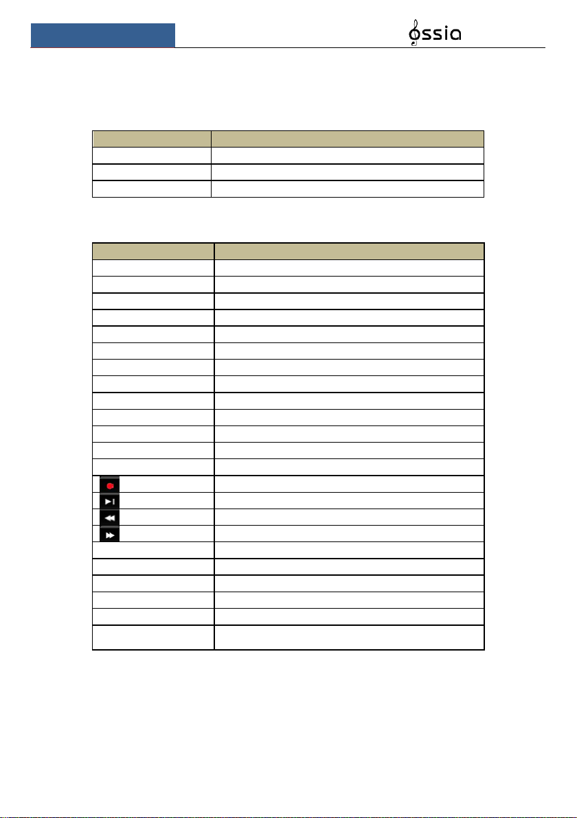
Type II (2U Models):
Name
Descriptions
Power
When powered on, the light is blue
HDD
The light turns blue when reading/writing HDD
Net
The light turns blue when the devices accesses the network
Backup
The light turns blue when backing up files and data
Play
The light turns blue when playing back video
REC
When recording, the light is blue
AUDIO /+
1. Adjust audio; 2. Increase the value in setup
P.T.Z / -
1. Enter PTZ mode; 2. Decrease the value in setup
MENU
Enter Menu
INFO
Check the information of the device
BACKUP
Enter backup mode in live
SEARCH
Enter search mode in live
Exit
Exit the current interface
Manual record
Play/Pause
Speed down
Speed up
1-9
Input digital number and select camera
0/--
Input number 0, the number above 10
Direction Key
Change direction
Multi-Screen Switch
Change the screen mode
Enter
Confirm selection
USB
To connect external USB device like USB mouse or USB
flash
Basic Operation Guide
User Manual
10
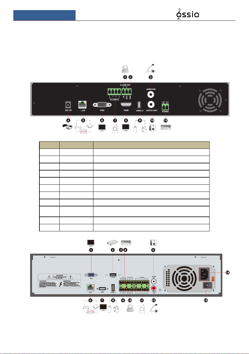
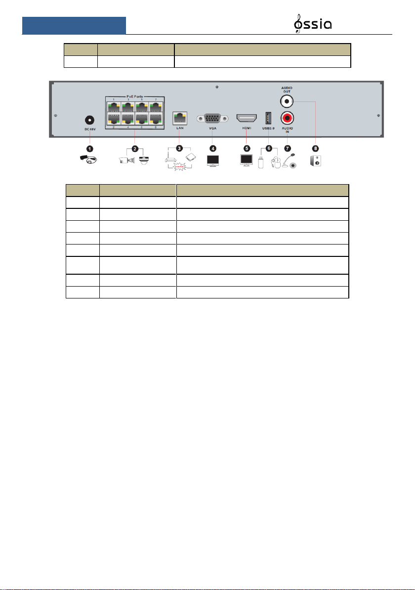
1.4 Rear Panel Descriptions
In this section we will introduce you to a few samples of rear panels. Of course we cannot
include all rear panels of all the available devices. Please take this manual as reference only.
No.
Name
Descriptions
1
ALARM OUT
Relay output; connect to external devices
2
GND
Ground connection
3
AUDIO IN
Audio input
4
DC12V
DC12V power input
5
LAN
Network port
6
VGA
Connect to VGA monitor
7
ALARM IN
Alarm inputs for connecting sensors
8
HDMI
Connect to HD display
9
USB
Connect USB storage device or USB mouse. USB3.0
interfaces will be colored in blue.
10
AUDIO OUT
Audio output
11
RS485
Connect to keyboard. A is TX+; B is TX-
Basic Operation Guide
User Manual
11
No.
Name
Descriptions
1
VGA
Connect to VGA monitor
2
e-SATA
Connect to HDD with e-SATA interface
3
RS485 Y/Z interface
Unavailable
4
RS485 A/B interface
Connect to keyboard. A is TX+; B is TX-
5
AUDIO OUT
Audio output
6
LAN
Network port
7
HDMI
Connect to HD display
8
USB
Connect USB storage device or USB mouse. USB3.0
interfaces will be colored in blue.
9
GND
Ground connection
10
ALARM OUT
Relay output; connect to external devices
11
ALARM IN
Alarm inputs for connecting sensors
12
AUDIO IN
Audio input
13
Power Switch
Press the switch to turn on/off the device
14
Power Supply
Power supply interface
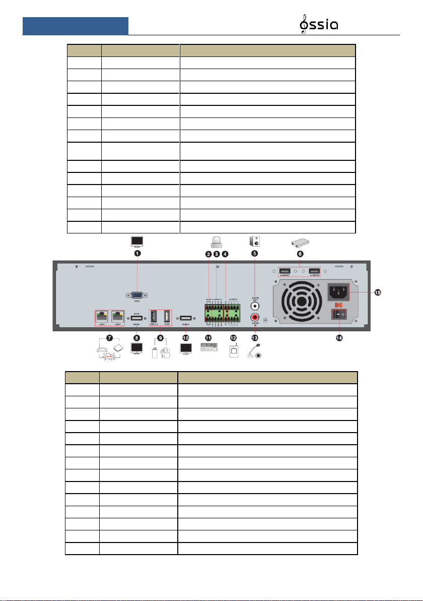
No.
Name
Descriptions
1
VGA
Connect to monitor
2
RS485 Y/Z interface
Unavailable right now
3
ALARM OUT
Relay output; connect to external alarm
4
GND
Grounding
5
AUDIO OUT
Audio output; connect to sound box
6
e-SATA1/ e-SATA2
Connect to HDD with e-SATA interface
7
LAN1/LAN2
Network ports
8
HDMI1
Connect to 4K×2K high definition display device
9
USB3.0/USB
USB3.0/2.0 interface, connect storage device or mouse
10
HDMI2
Connect to 1920×1080 high definition display device
11
RS485 A/B interface
Connect to keyboard. A is TX+; B is TX-
12
ALARM IN
Alarm inputs for connecting sensors
13
AUDIO IN
Audio input
14
Power Switch
Press the switch to turn on/off the device
Basic Operation Guide
User Manual
12
No.
Name
Descriptions
15
Power Supply
Power supply interface
No.
Name
Descriptions
1
Power Supply
DC48V power supply interface
2
PoE port
8 PoE network ports; connect to 8 PoE IP cameras
3
LAN
Network port
4
VGA
Connect to VGA monitor
5
HDMI
Connect to HD display (4K Ultra HD Supported)
6
USB3.0
USB3.0 interface, connect USB storage device or
USB mouse
7
AUDIO IN
Audio input
8
AUDIO OUT
Audio output
1.5 Connections
Video Output Connections
Video Output: Supports VGA/HDMI/CVBS/Spot video output (Depends on models). You can
connect to monitor through these video output interfaces simultaneously or independently.
Audio Connections
Audio Input: Connect to microphone, pickup, etc.
Audio Output: Connect to headphone, sound box or other audio output devices.
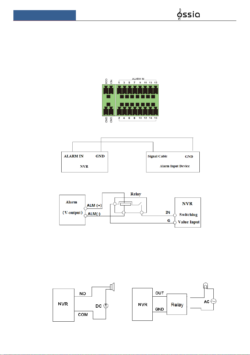
Alarm Connections
Only selected models support this function. See below 16 CH alarm inputs and 1 CH alarm
output for example.
Basic Operation Guide
User Manual
13
Alarm Input (Availability depends on model):
Alarm IN 1~16 are 16CH alarm input interfaces. There are no type requirements for sensors.
NO type and NC type are both available and can be configured from the device interface.
The method to connect sensors to the device is as shown below:
The alarm input is an open/close relay. If the input is not an open/close relay, please refer to the
following connection diagram:
Alarm Output (Availability depends on model):
The way to connect alarm output device:
Pull out the green terminal blocks and loosen the screws in the alarm-out port. Then insert the
signal wires of the alarm output devices into the port of NO and COM separately. Finally,
tighten the screws. Provided that the external alarm output devices need power supply, you can
connect the power supply as per the following figures.

Basic Operation Guide
User Manual
14
RS485 Connection
There are two types of RS485 interfaces:
(Type 1) (Type 2)
Type 1: The P/Z is for PTZ cameras – Not applicable for NVR devices. The K/B interface is
used to connect the C06 control keyboard.
Type 2: The RS485 interface is used to connect control keyboard and PTZ cameras (This
connector cannot be used for PTZ control in NVR devices. A is TX+; B is TX-.
2 Basic Operations Guide
2.1 Startup & Shutdown
Please make sure all the connections are done properly before you power on the device. Proper
startup and shutdown are crucial for prolonging the lifespan of the device.
2.1.1 Startup
① Connect the output display device to the VGA/HDMI interface of the device.
② Connect the USB mouse and network cable
③ Connect the power. The device will boot and the power LED would turn blue.
④ A WIZARD window will pop up (you should select the display language the first time you
use the device). Refer to 3.1 Startup Wizard for details.
2.1.2 Shutdown
You can power off the device by using the remote controller or USB mouse.
By remote controller:
① Press the power button. This will take you to a shutdown window. The unit will power off
after a while by clicking “OK” button.
② Disconnect the power.
By mouse:
① Click StartShutdown to pop up the Shutdown window. Select “Shutdown” in the
window. The unit will power off after a while by clicking “OK” button.
② Disconnect the power.

Basic Operation Guide
User Manual
15
2.2 Remote Controller
① Open the battery cover of the remote controller and insert two AAA size batteries.
② When placing the batteries. Please ensure the correct polarity (+ and -).
③ Replace the battery cover.
Key points to check in case the remote doesn’t work.
1. Check batteries polarity.
2. Check if the batteries are not dead
3. Check IR controller sensor for any interference.
Button
Function
Power Button
Switch off—to stop the device
Record Button
To start recording
-/-- /0-9
Input number or choose camera
Fn1 Button
Unavailable temporarily
Multi Button
To choose multi screen display mode
Next Button
To switch the live image
SEQ
To go to sequence view mode
Audio
To enable audio output in live mode
Switch
No function temporarily
Direction button
To move cursor in setup or pan/title PTZ
Enter Button
To confirm the choice or setup
Menu Button
To go to menu
Exit Button
To exit the current interface
Focus/IRIS/Zoom/PTZ
To control PTZ camera
Preset Button
To enter into preset setting in PTZ mode
Cruise Button
To go to cruise setting in PTZ mode
Track Button
No track function temporarily
Wiper Button
No function temporarily
Light Button
No function temporarily
Clear Button
No function temporarily
Fn2 Button
No function temporarily
Info Button
Get information about the device
To control playback. Play(Pause)/Stop/Previous
Frame/Next Frame/Speed Down/Speed Up
Snap Button
To take snapshots manually
Search Button
To go to search mode
Cut Button
No function temporarily
Backup Button
To go to backup mode
Zoom Button
To zoom in the images
PIP Button
No function temporarily
Note:
You shall press the P.T.Z button to enter the PTZ interface. Choose a channel and press P.T.Z button
again to hide the P.T.Z control panel. Then you can then press preset, cruise, track, wiper or light button
to enable the relevant function.
Basic Operation Guide
User Manual
16
2.3 Mouse Control
➢ Mouse control in Live Preview & Playback interface
In the live preview & playback interface, double click on any camera window to show the
video in single screen mode; double click the window again to restore it to the previous split.
If the interfaces display in full screen, move the mouse to the bottom or to the right side of the
interface to pop up the relevant tool bar. The tool bar will disappear automatically after you
move the mouse away from it;
Mouse control in text-input
Move the mouse to the text-input box and click the box. When required to input text the
keyboard will pop up automatically.
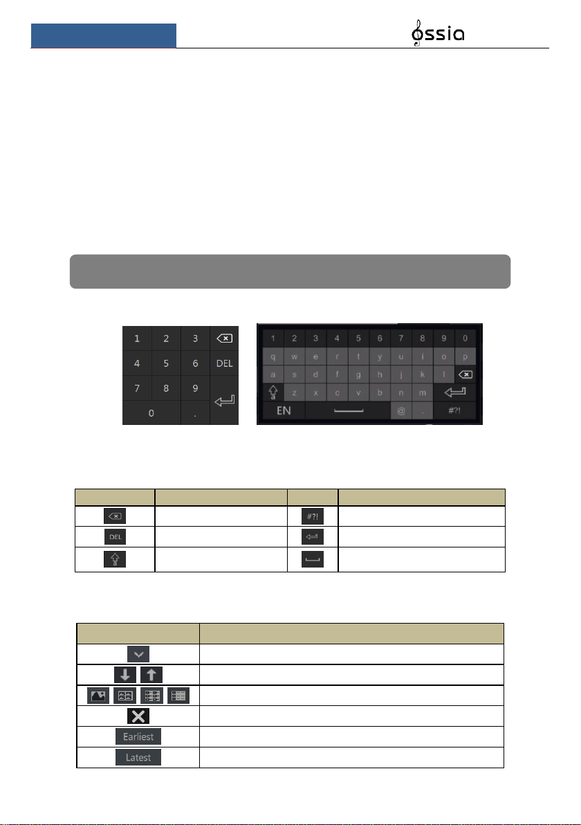
2.4 Text-input Instruction
The system includes two input keyboard layout as shown the above pictures. The left box is the
number input keyboard and the right box is the general input keyboard which provides inputs
of numbers, letters and punctuation characters as shown below
Button
Meaning
Button
Meaning
Backspace key
Switch to punctuation characters
Delete Key
Enter key
Switch key between upper
and lower-case letters
Space key
2.5 Other Button Operations
Button
Meaning
Show the menu list.
Change the sequence order within the list.
Change the camera display mode.
Close the current interface.
Go to the earliest date of camera recording.
Go to the latest date of camera recording.
Note: The mouse is the default controller for all operations unless mentioned otherwise.
Wizard & Main Interface
User Manual
17
3 Wizard & Main Interface
3.1 Startup Wizard
On each startup, the disk icons will be shown on the top of the interface. You can view the
number and status of each disk quickly and conveniently through these icons
1) No disk
2) Unavailable disk
3) R/W available disk
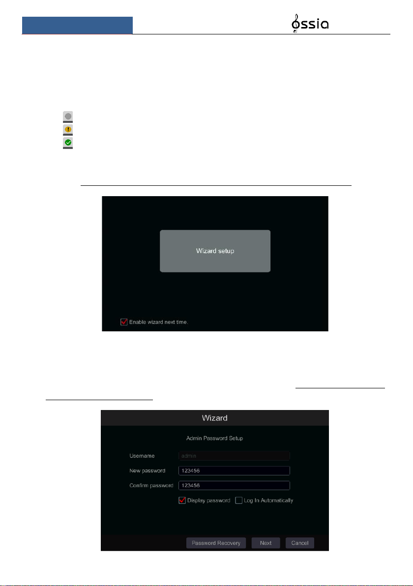
You can quickly and easily configure the device using the setup wizard. The wizard can also be
skipped and will be shown in the next startup unless the “Enable wizard next time” was
unticked. Skipping the wizard will automatically set the default password to “123456”
Click “Wizard Setup” to start. The setting steps are as follows:
① Admin settings. (Appears only one time – on the first system startup): Set your own admin
password or use the default when you use the wizard for the first time (the default username is
admin skipping this part will set the default password to “123456”); It is highly advisable to
change the default password.
Wizard & Main Interface
User Manual
18
Click on “Edit Security Question” to set questions and answers for password recovery. If you
will ever forget the password – these questions will be used to restore the password to factory
default. Please refer to Q4 in Appendix A FAQ for details. Skipping this step will force you to
contact the technical support in case the password will be forgotten. There is no other
way for the user to independently recover the admin password except of this method..
Click “Next” to continue or click “Cancel” to exit the wizard.
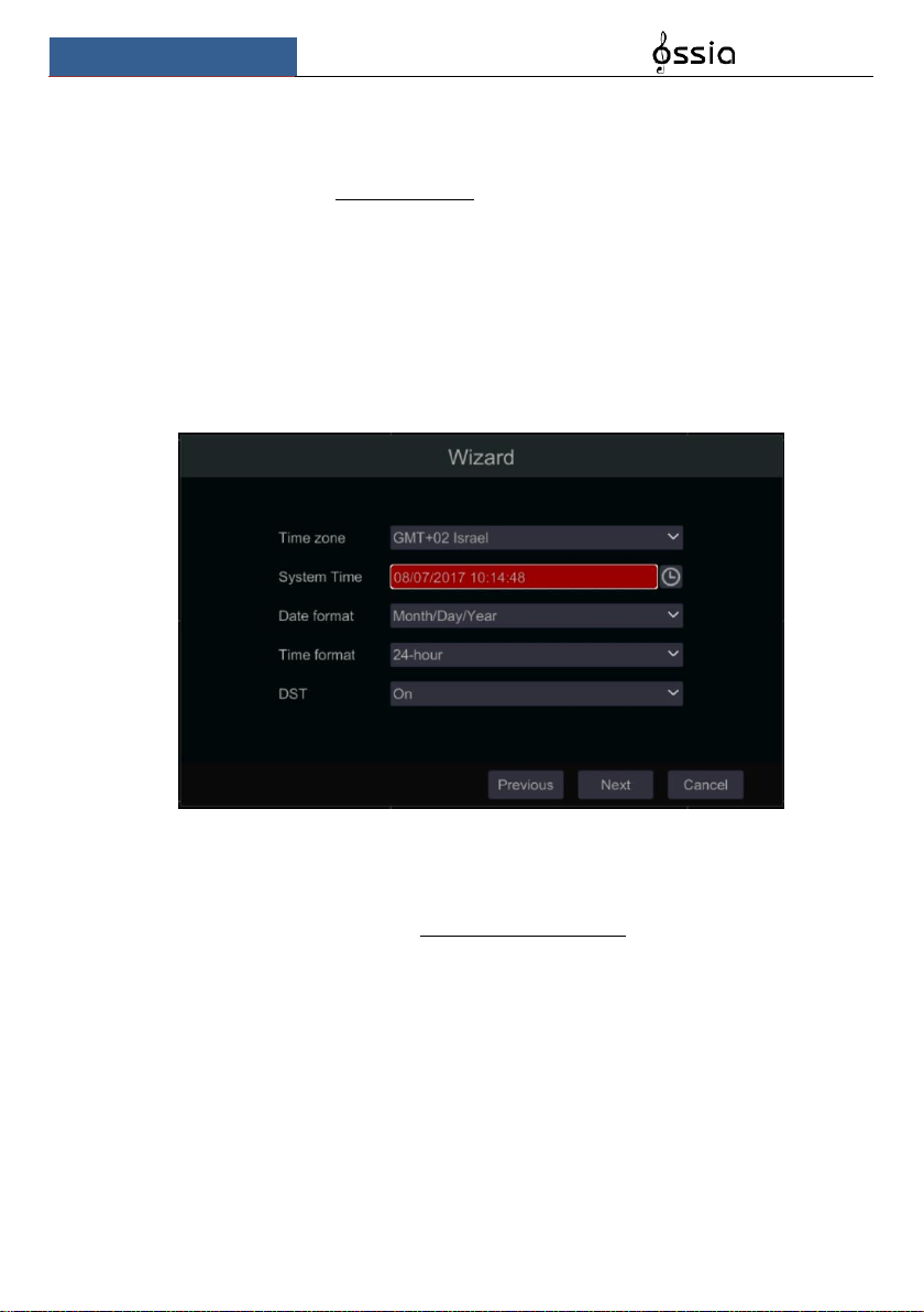
② Date and Time Configuration. (Appears only one time – on the first system startup):
The date and time of the system must be configured when you use the wizard for the first time.
Set the time zone, system time, date format and time format. The DST will be enabled by
default if the time zone selected includes DST. Click “Next” to continue.
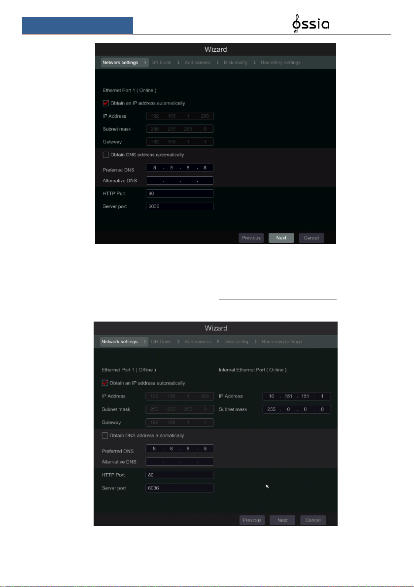
③ Network Settings - general. Check “Obtain an IP address automatically” and “Obtain
DNS automatically” to get the IP address and DNS automatically (You must have a DHCP
Service enabled in your network). Uncheck it in order to input it manually. Input the HTTP port,
RTSP port and Server port (please see 11.1.2 Port Configuration for details). Click “Next” to
continue.
Wizard & Main Interface
User Manual
19
Picture reference for DVR/Non-PoE NVR
Network setting – PoE NVRs:
If you use PoE NVR, the state of the internal ethernet port will be shown on the interface as
seen on the picture below. Please refer to 11.1.1 TCP/IPv4 Configuration for detailed
introduction of the internal ethernet port.
Picture reference for PoE NVR
Wizard & Main Interface
User Manual
20
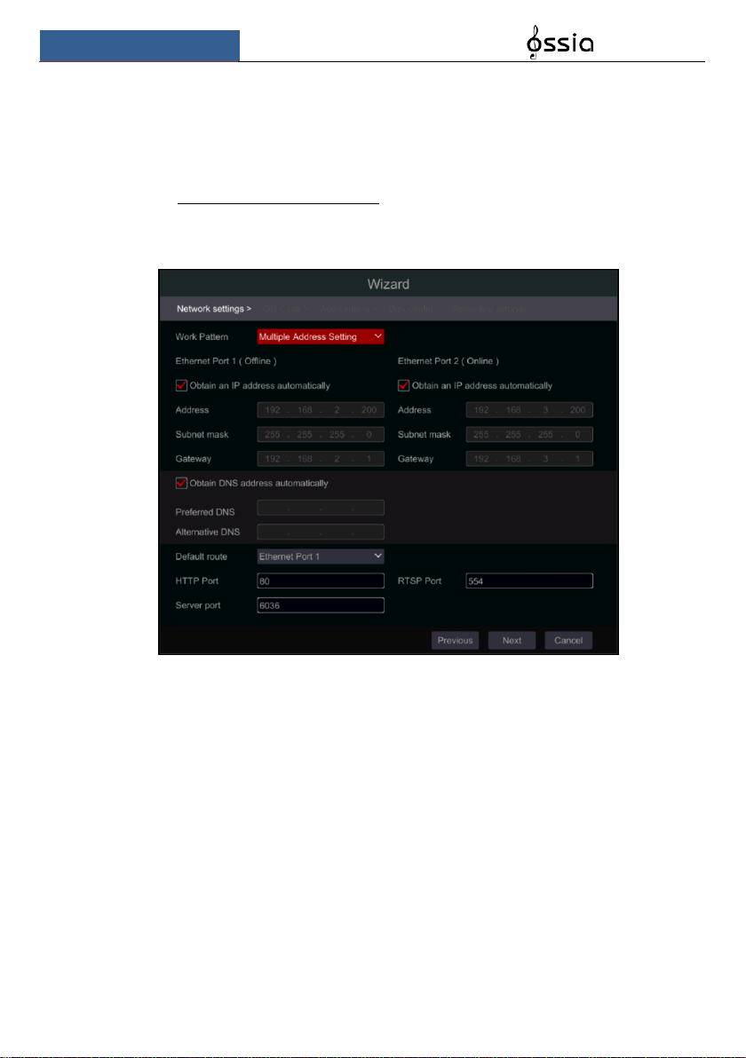
Professional models with 2 Ethernet ports: Some devices support 2 ethernet ports. The ports
can work in 2 ways – “Multiple Address Setting” which means that the device will get 2 IP
addresses and both addresses are always active. The second option is “Network fault tolerance”
which means that only the primary ethernet port is active at a given time. If the primary
network develops a fault – the device will automatically switch to the secondary ethernet port.
Please refer to 11.1.1 TCP/IPv4 Configuration for additional information.
For “Multiple Address Setting” you will need to set 2 different addresses (Static or DHCP) and
one DNS address. You can set the default ethernet port for DNS routing.
Wizard & Main Interface
User Manual
21
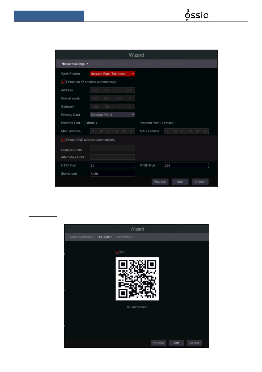
For “Network fault tolerance” you will need to set a single address (Static or DHCP) and DNS
address. The 2 networks should be in the same IP Segment. You can also set the primary
ethernet card.
④ QR Code: You can enable the NAT service and scan the QR Code using the “Provision
Cam 2” mobile application to quickly connect to the device. Please refer to 12.1 Mobile
Surveillance for additional information.
Wizard & Main Interface
User Manual
22
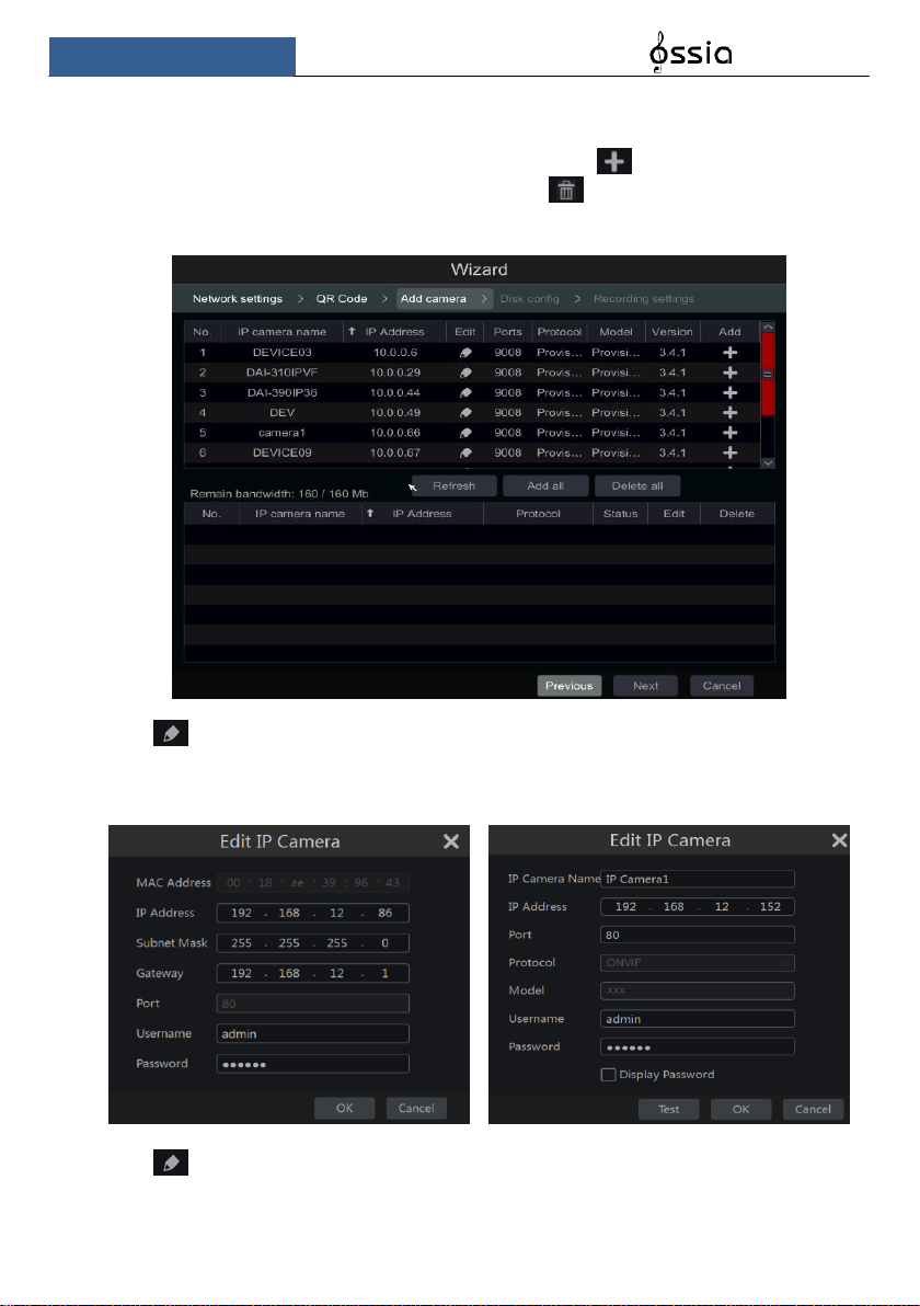
⑤ Add Camera. This section is available only in NVRs and Hybrid DVRs. It is applicable
for IP cameras only. Connected analog cameras will be displayed automatically. Click
“Refresh” to refresh the list of available IP cameras and click to add the checked camera.
Click “Add All” to add all the cameras in the list. Click to delete the added camera. Click
“Delete All” to delete all the added cameras.
Click to edit the network parameters of the selected IP camera as shown on the left below.
Input the new IP address, subnet mask and gateway. Fill the current username and password of
the camera. Click “OK” to save the settings.
Click to edit the added camera as shown on the above right. Input the new camera name,
IP address and port. Fill the current username and password of the camera. You can click “Test”
Wizard & Main Interface
User Manual
23
to test the effectiveness of the filled information. Click “OK” to save the settings. You can
change the IP camera name only when the camera is added and online. Click “Next” to
continue.
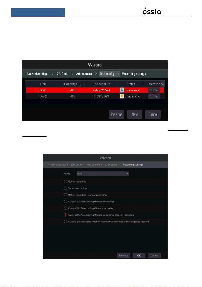
⑥ Disk Settings. You can view the disk status, number, capacity and serial number. Click
“Format” to format the disk. Click “Next” to continue.
⑦ Record Settings. Two record modes are available: Auto and Manual. See 7.1.1 Mode
Configuration for details.
Auto: Select the desired auto mode in the interface as shown below and click “OK” button to
save the settings.
Wizard & Main Interface
User Manual
24
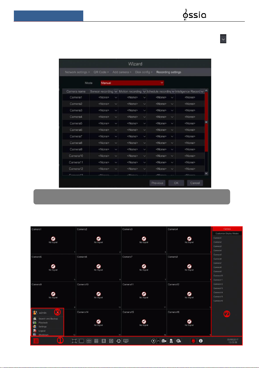
Manual: After switching to manual, set the schedule for “Sensor Record”, “Motion Record”
and “Schedule Record” of each camera. (You can choose all together by clicking on . Click
“OK” to save the settings.
3.2 Main Interface
3.2.1 Main Interface Introduction
Note: Only NVRs and Hybrid DVRs will have the “Analytics” Option.
Wizard & Main Interface
User Manual
25
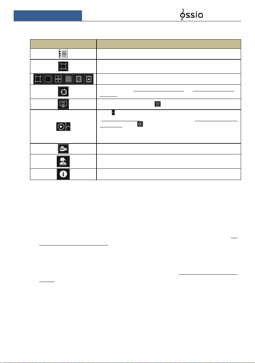
Operations bar (① ) icon description:
Button
Meaning
Start button. Click it to pop up the menu (③).
Full screen button. Click it to switch to full screen mode; click it again to
exit the full screen mode.
Screen split mode buttons.
Dwell button (see 5.2.2 Quick Sequence View and 5.2.4 Scheme View In
Sequence for details).
Click it to enable OSD; click to disable OSD.
Click to set the default playback time for in-channel instant playback
(8.1 Instant Playback) and all channel playback (8.2 Playback Interface
Introduction); click to activate quick playback for all channels – going
back to the specified time. For instance, if you choose “5 minutes ago” as
the default playback time, you can playback the record from the past five
minutes.
Manual record button. Click it to enable/disable manual record.
Manual alarm button. Click it to manually trigger or clear the alarm-out
Information button. Click it to view system information.
Introduction of area ② :
A) Click “Camera” to view all the cameras available for display. Either select one window on
the left side of the interface and double click on the camera name you wish to view in the
selected window or drag a camera name from the right pane to the selected window on the
left.
B) Click “In-Channel Sequence” to view all the configured “In-Channel Sequence” groups
list; Select a group in the list to view all the cameras related to that group. (Refer to 4.2
Add/Edit In-Channel Sequence for detailed information). Either select one window on the
left side of the interface and double click on the group you wish to view in the selected
window or drag a group name from the right pane to the selected window on the left.
C) Click “Display Presets” to view your saved presets (refer to 5.2.1 Preview By Display
Presets for detailed explanation of the display presets). Double click on the desired display
preset from the list to activate it.
Wizard & Main Interface
User Manual
26
Introduction of area (③):
Icon / Button
Meaning
Showing the current user name
Record search and backup interface, see 8.3 Record, Search, Playback
& backup for details.
Playback interface .see 8.2 Playback Interface Introduction for details.
Setup panel, see 3.2.2 Setup Panel for details.
Log out of the system.
Perform “Logout”, “Reboot” or “Shutdown”
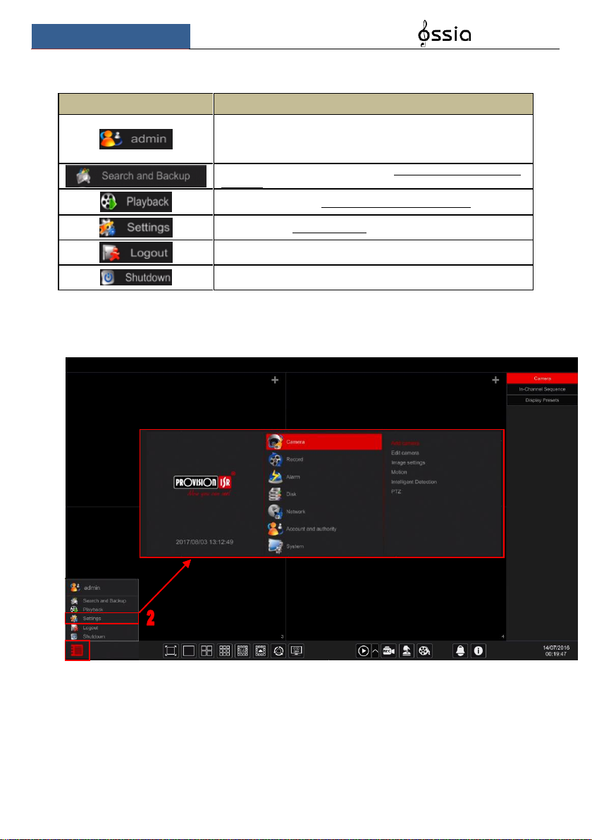
3.2.2 Setup Panel
Click StartSettings to pop up the setup panel as shown below.
The setup panel includes seven categories. Each category contains sub-categories that will link
you to the desired configuration interface.
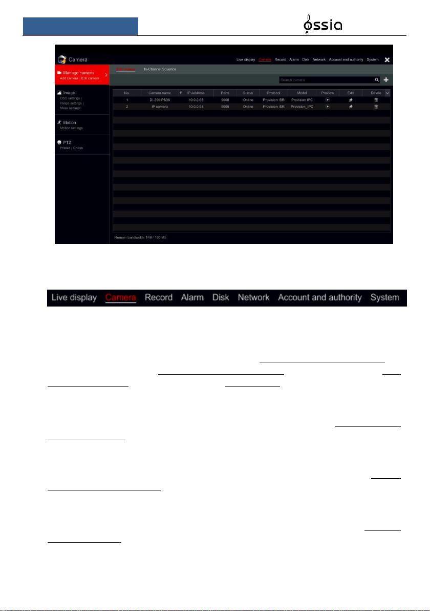
Here we take Camera category as an example. The Camera Category provides links such as
“Add Camera”, “Edit Camera”, “Image Settings”, “Motion” and “PTZ”. Click Camera and
“Add Camera” to go to the camera management interface as shown below.
Wizard & Main Interface
User Manual
27
Click the main categories on the top of the screen to go to corresponding interface. Refer to the
picture below. For instance, you can go to system setup interface by clicking “System” tag.
3.2.3 Main Functions
➢ Camera
Offers functions such as Camera Management (see Chapter 4 Camera Management for
details), Image Settings (see 5.3 Preview Image Configuration for details), Motion (see 9.2.1
Motion Configuration for details) and PTZ (see Chapter 6 PTZ for details).
➢ Record
This category covers Encode Parameters and Record Schedules. Please see Chapter 7 Record
& Disk Management for details.
➢ Disk
Her you will find Disk Management, Storage Mode and Disk Information. Please see Chapter
7 Record & Disk Management for details.
➢ Alarm
Configure Sensor and Motion Alarm Handling and Alarm Out Settings. Please see Chapter 9
Alarm Management for details.
➢ Network

Wizard & Main Interface
User Manual
28
This category contains TCP/IPv4, DDNS, Port, E-mail and Network Status. Please see 11.1
Network Configuration for details.
➢ Account and Authority
This category covers Account Management (see 10.1 Account Management for details) and
Permission Management (see 10.3 Permission Management for details).
➢ System
The category shows Basic Configuration (see 11.2 Basic Configuration for details), Device
Information (see 11.7 View System Information for details), Log Information (see 11.6 View
Log for details) and Configuration File Import & Export (see 11.5 Backup and Restore for
details).
Live Preview Introduction
User Manual
29
4 Camera Management
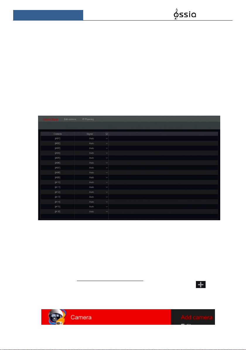
4.1 Camera Signal (Applicable only for DVRs)
All of the DVRs sunning Ossia OS support 4in1 technology (AHD / CVI / TVI / Analog). The
default setting for video signal is “Auto” which means that the DVR will automatically
recognize the camera signal and device which technology it is using. In some cases, the auto
recognition fails – which will cause the video to come up in black & white or not to come up at
all. In such cases, you will have to set the signal manually.
① Click StartSettingsCameraCamera Signal
② Choose the relevant channel (By number) and set the signal to the required one (Choose
out of Auto/CVI/TVI). CVBS signal will be recognized automatically in all conditions.
4.2 Add/Edit Camera
4.2.1 Add Camera (Applicable only for NVRs and Hybrid DVR models)
For Non-Hybrid DVRs: the camera will be displayed automatically once connected to the
BNC port. If the image does not appear on the screen please check the camera’s power supply
and video connection.
For NVRs and Hybrid DVRs: The device’s network parameters should be configured before
adding IP cameras (see 11.1.1 TCP/IPv4 Configuration for details).
Referring to the pictures below, Click on Add Camera in the setup panel or in the top
right corner of the preview window to pop up the “Add Camera” window as shown below. You
can use the “quick add” interface to add an IP Camera or add it manually.
 Loading...