

Page 1

Page 2

2
1. Motorcycle specications
2. Engine part
2.1 Assembling or dismantling the engine from the chassis
2.2 Assembly and disassembly of engine parts
2.2.1 Engine start
2.2.2 Clutch
2.2.3 Gears
2.2.4 Ignition
2.2.5 Cylinder head
2.2.6 Cylinder
2.2.7 Piston and rings
2.2.8 Ignition
2.2.9 Ignition inner cover
2.2.10 Crankshaft
2.2.11 Water pump
3. Cycle part
3.1 Periodic maintenance chart and torque values.
4. Electrical part
4.1 Electrical diagrams
4.2 Injection
4.2.1 Kscan
4.2.2 Kwrite
5. Manintenance
5.1 Cylinder cover
5.2 Cylinder
5.3 Piston and rings
5.4 Crank
5.5 Crankshaft
5.6 Clutch
5.7 Gears
5.8 Transmission
5.9 Bearings
5.10 Seals
5.11 Sparkplug
5.12 Motor oil
CONTENTS
Page 3

3
MOTOR
Cubic capacity 272,2 cc
Type Single cylinder, two-stroke, inverted engine with reed block
air intake.
Cooling system Liquid
Bore x stroke 76x60 mm
Fuel injection EFI Kokusan Batery-less System
Ignition Volante magnético digital CDI Kokusan
Clutch Hydraulic
TRANSMISSION
Gearbox 6 speeds
Transmission transmission by gears, nal transmission by chain
Lubrication mixture 100% synthetic oil lubrication 0.9%
Transmission and clutch oil 350 cc. of Gear Extreme type 75 W oil.
CHASIS
Type Cr-Mo / Forged aluminium with patented Fuel Tank by OSSA
Front suspension Marzocchi Hydraulic Fork with 40 mm al. stanctions.
Adjustable rebound and compression.
Shock absorber Progressive hydraulic monoshock TTX OHlins with
adjustable rebound and compression
Front brake ø 185 mm disc and 4 piston caliper
Rear brake ø 150 mm disc with 2 piston caliper
Front Wheel 28 spoke rims and 2,75x21 tires
Rear wheel 28 spoke rims and 4,00x18 tubeless tire
Engine protector Made of AA7075 T6
Kickstart pedal Forged aluminium
Gearshift and brake pedals Forged aluminium with retactable tips.
WEIGHT AND DIMENSIONS
Wheelbase 1.328 mm
Seat heigth 655 mm
Ground clearance (unloaded) 340 mm
Fuel tank capacity 2,6 litros
Weight (no fuel) 64 Kg
OSSA Factory S.L. reserves the right to modify this manual without notice. Kokusan, Marzocchi, OHlins
are registered brands and the use of their name is under license.
TECHNICAL FEATURES
Page 4
4
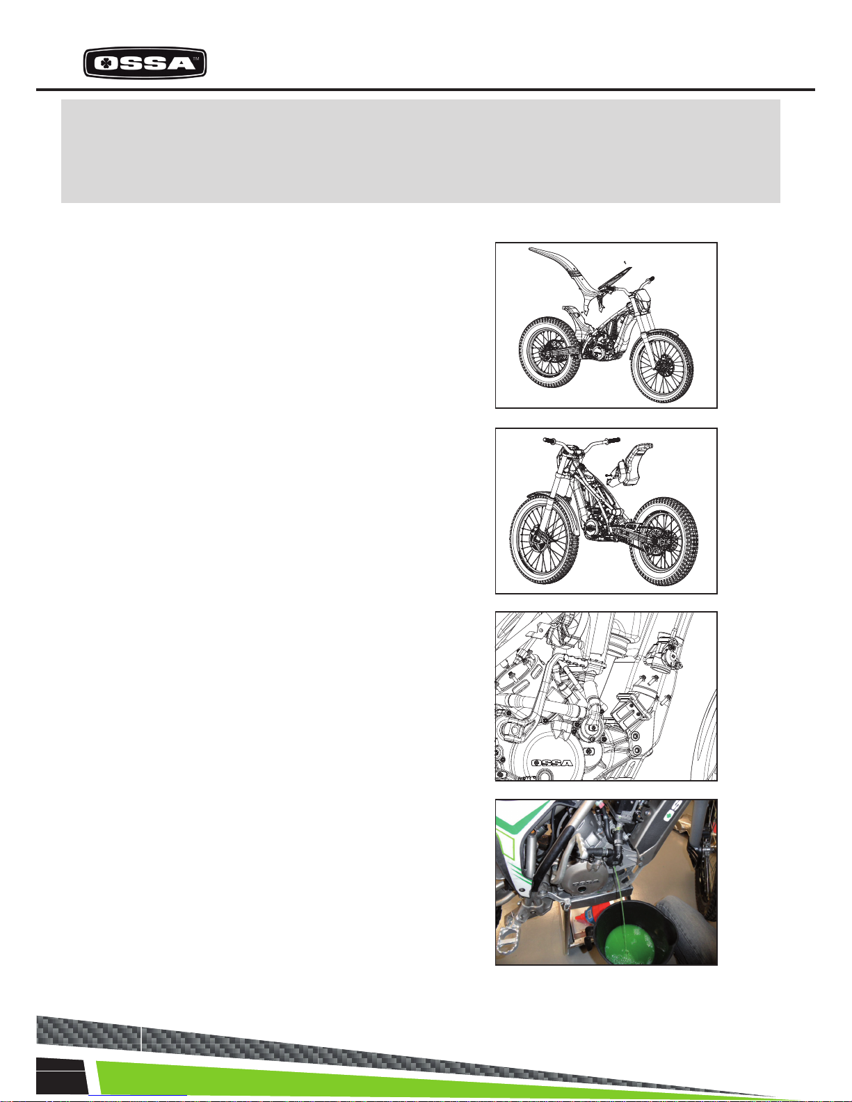
All operations on the engine of TR280i can be done without taking it appart from the chassis, except
when it is needed to work on the fuel pumps situated at the bottom of the fuel tank. For this case or to
work more comfortably on other operations, this is the procedure to disassemble the engine from the
chassis.
1. Take off the plastic lter cover and
seat base.
2. Take off the exhaust.
3. Take off the reed block and the throttle
body assembly.
4. Empty the cooling circuit and take off
the radiator.
ENGINE PART
Page 5
5
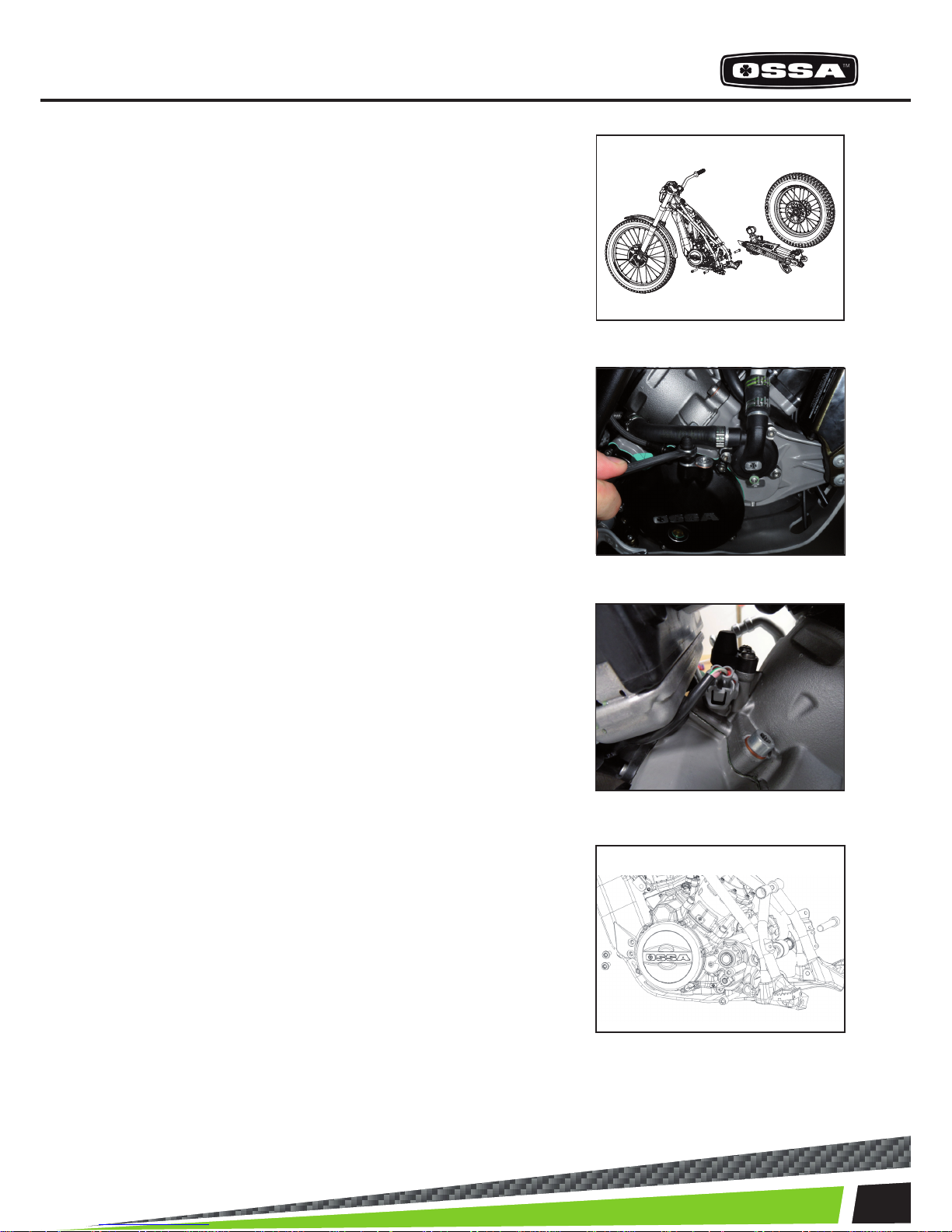
ASSEMBLY AND DISASSEMBLY OF THE ENGINE FROM THE CHASSIS
9. Remove the bolts that hold the engine to the chassis,
to proceed with its disassembly.
8. Disconnect the cables from the injector.
7. Empty the clutch oil and remove the hose from the engine.
5. Take off the rear wheel, the swing arm, the shock absorber and the brake pump from the chassis.
Page 6
6
ENGINE PARTS
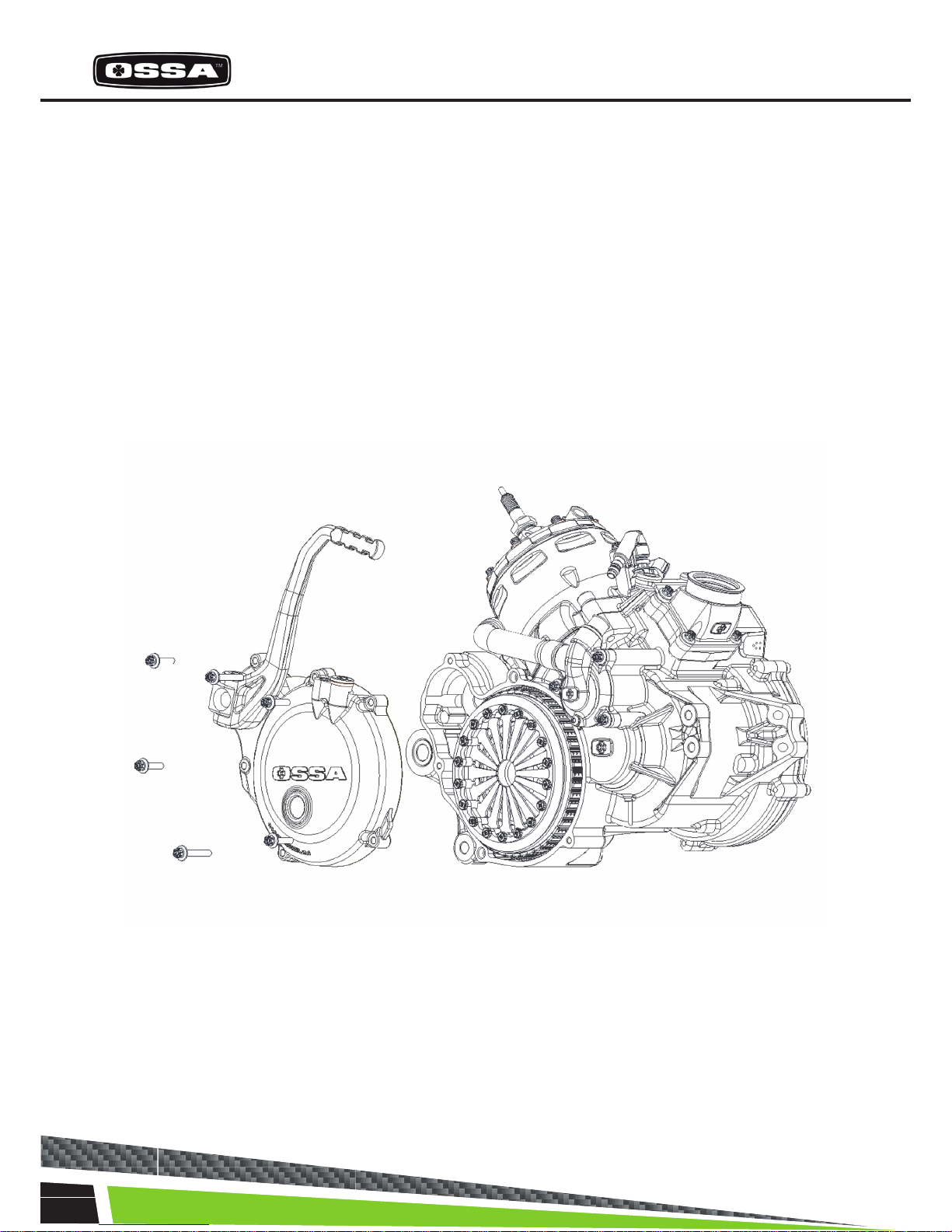
1- STARTING SYSTEM
Before taking appart the starting system, you must make sure the engine has no oil in the crankcase
leaning the bike to both sides. Also the clutch oil, removing the hose from the clutch cover.
Unscrew the 6 bolts that hold the clutch cover on the crankcase and take of the cover toghether with
the ignition system, kickstart pedal, shaft and gear.
Be careful to avoid damaging the gasket when removing the cover.
Page 7
7
ENGINE ASSEMBLY AND DISASSEMBLY
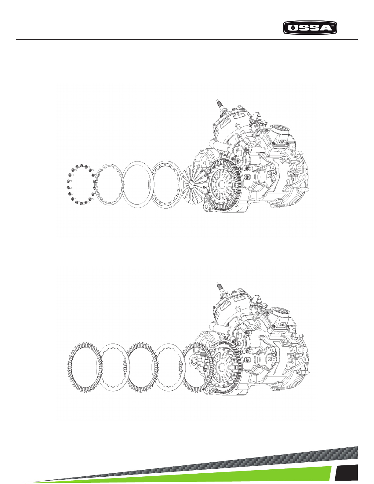
2- CLUTCH
Once the clutch cover is out, you can see the clutch system. Follow these steps to take it appart.
Take out the 18 bolts which hold the clutch spring support plate.
Take off the spring, the pressure plate and the 18 clutch release arms to access the clutch discs.
Remove the clutch discs.
Page 8

8
ENGINE PARTS
3- GEAR SHIFTING ASSEMBLY
Once you have taken out the clutch discs, the clip that holds the countershaft sprocket, the sprocket,
the bushing with its two O-rings and the gear shifting pedal, we can separate the gear assembly from the
engine.
The gear system comes out toghether with the shift shaft, and the gear selector assembly. To take it out of
the crankcase, it is necessary to remove the 5 centering screwst; and with some gear engaged, proceed
to take it out, as shown.
Take off the elastic ring ‘circlip’, the sprocket and the
gear shifting pedal.
Remove the 5 bolts that x the gear assembly to the crankcase. To
be able to take out the 3 bolts situated behind the clutch crown, the
crown must be turned until the rounded spaces for the key coincide
with the bolt heads.
After removing them, the gear assembly can be taken out of the crankcase.
Page 9
9
ENGINE ASSEMBLY AND DISASSEMBLY
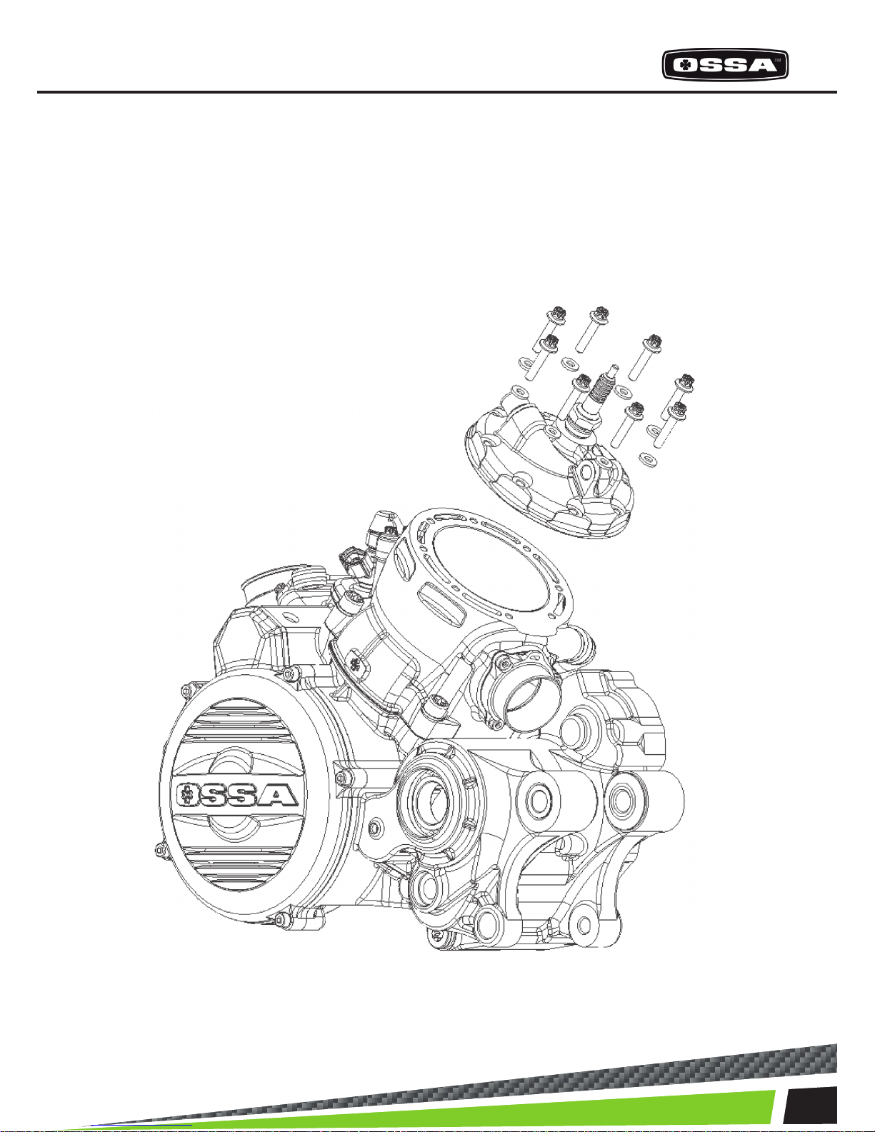
4- CYLINDER HEAD
It is recommendable to take out the cooling system hoses which are connected to the cylinder head with zip-ties, and the temperature sensor. After this, the cylinder head can
be disassembled by unscrewing the 8 bolts which hold it toghether with the cylinder.
Page 10
10
ENGINE PARTS
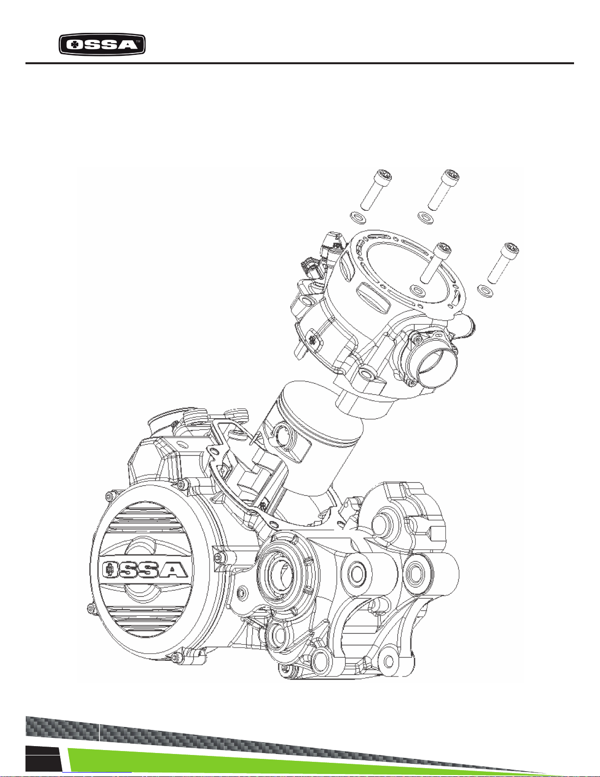
5- CYLINDER
Before taking the cylinder appart from the engine, it is recommendable to remove the hoses from the
cooling system. To proceed, the 4 bolts that x the cylinder to the crankcase must be taken out.
Page 11
11
ENGINE ASSEMBLY AND DISASSEMBLY
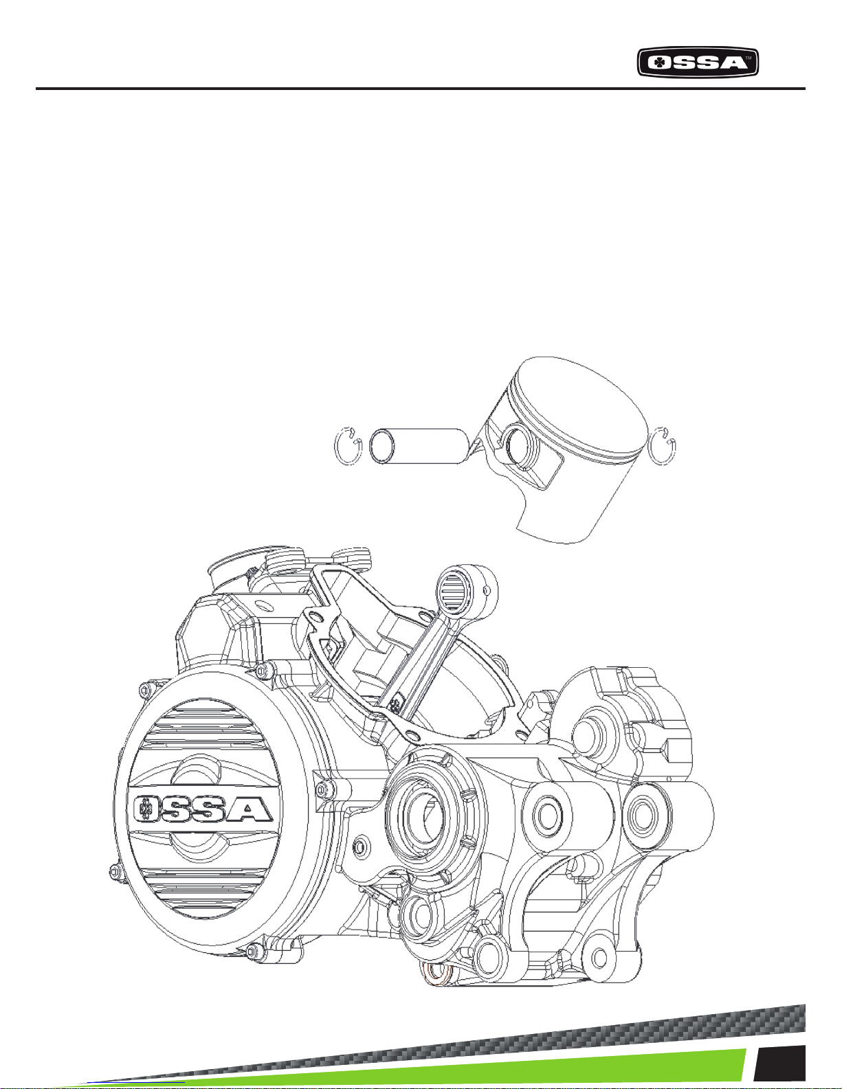
6- PISTON AND RINGS
Once the cylinder is out, the next step is to take out the cylinder and the rings, removing the locking
snap rings and the piston pin, we can take the piston appart from the rod, and then remove the rings
if desired.
Page 12

12
ENGINE PARTS
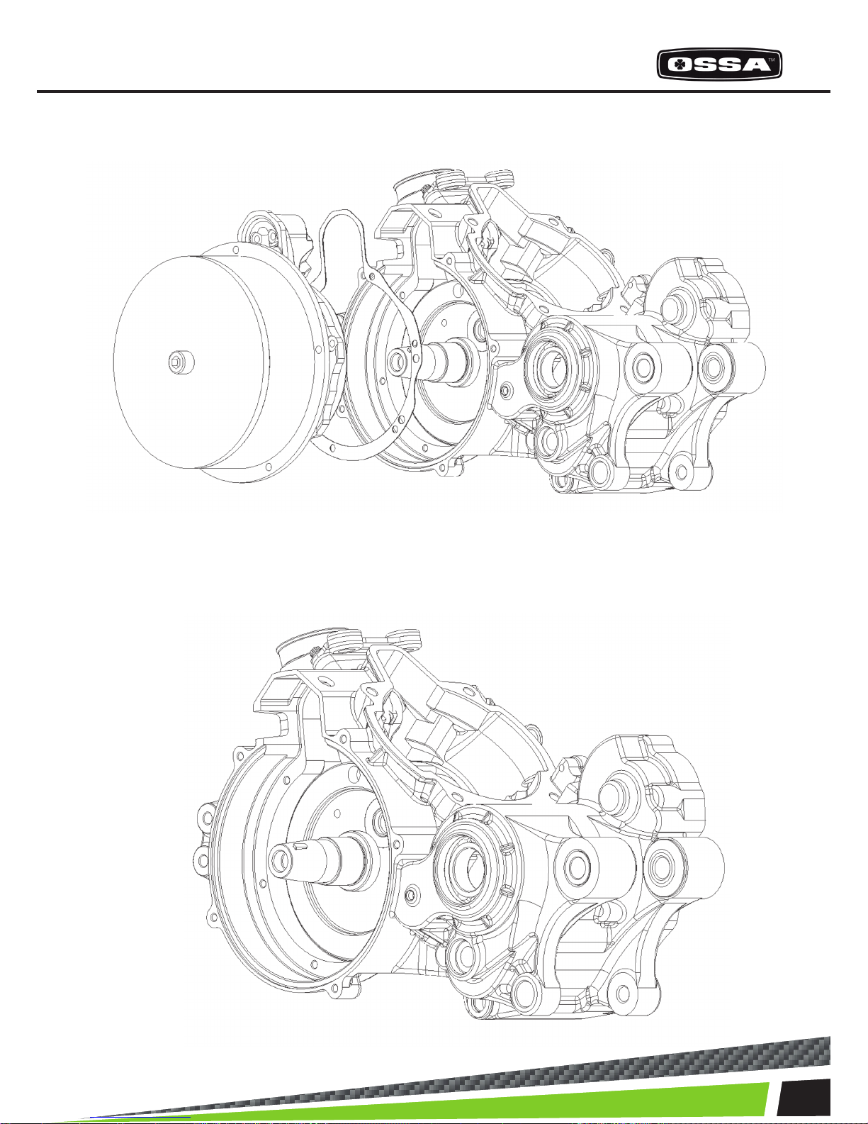
7- IGNITION SIDE
If we remove the ignition cover we can access the rotor. Once the rotor is out we can get to the stator.
Remove the 5 bolts from the ignition cover.
Using the special tool (included in the tool kit Ossa ref. 1499960211) we can take out the rotor.
Page 13

13
ENGINE ASSEMBLY AND DISASSEMBLY
We can proceed to remove the stator, taking out the bolts that hold it toghether with the inner crankshaft cover, toghether with the pick-up.
Page 14

14
ENGINE PARTS
8- INNER CRANKSHAFT COVER
Once the stator and rotor are out, the inner crankshaft cover can be removed. It is held toghether with
the crankshaft by 6 bolts. It is necessary to use the extractor kit which is part of the Ossa workshop
toolkit (ref. 1499960211). After this step, the crankshaft can be accessed.
After unscrewing the 6 bolts we attatch the extractor tool at the centre of the inner crankshaft cover
and we pull it out using the extractor that ts in the crankcase, while we screw the bolt in the middle.
Page 15
15
ENGINE ASSEMBLY AND DISASSEMBLY
Using the tool we take out the inner crankshaft cover. Be careful to avoid damaging the gasket.
Page 16
16
ENGINE PARTS
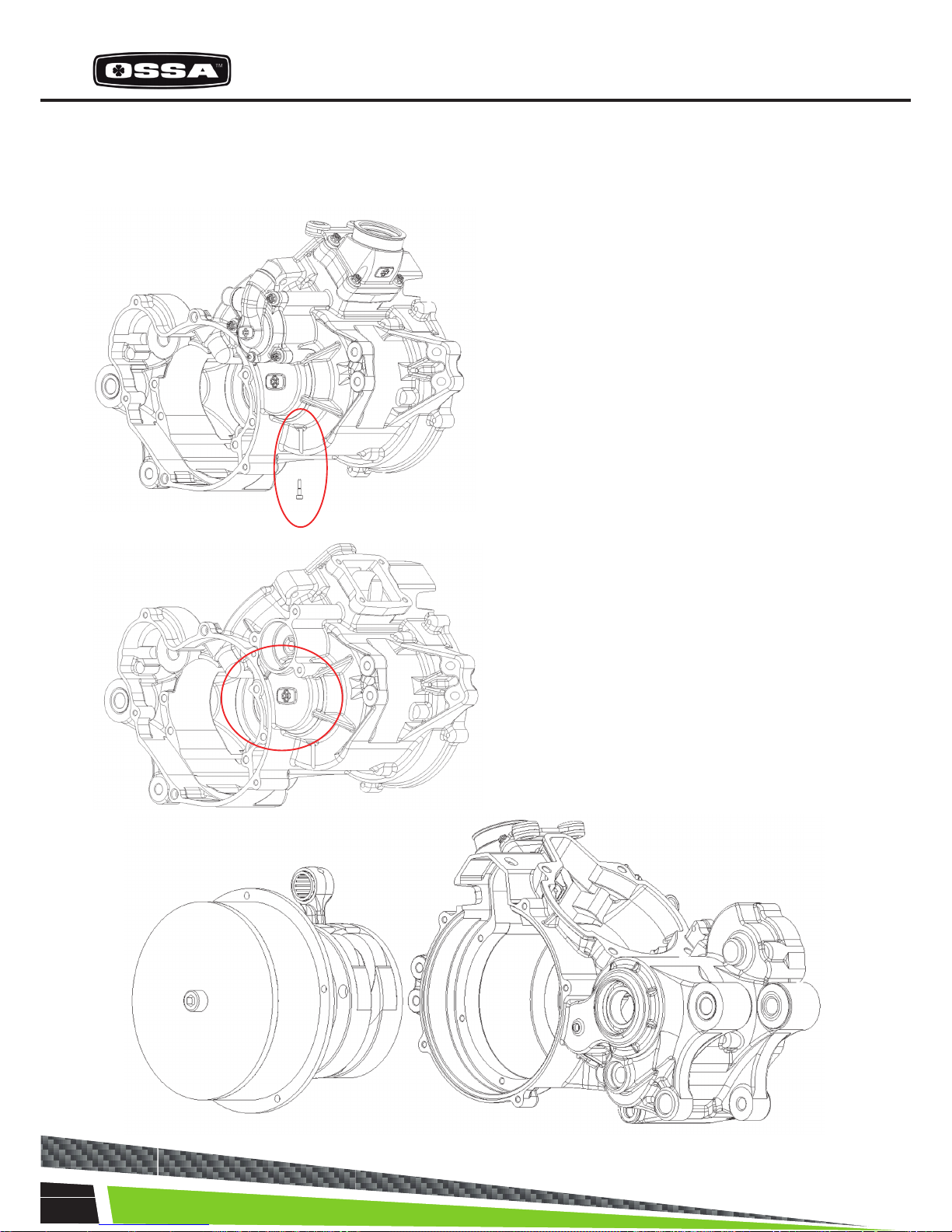
9- CRANKSHAFT
To remove the crankshaft it is necessary to use the special tools. (ref. 1499960211)
Follow these steps:
1
2
Unscrew the long pin that locks the bearing of the
crankshaft (1).
Heat up the area in the circle (2) with a heat
blower so that the crankshaft expands and makes
the extraction of the crankshaft easier.
Page 17
17
ENGINE ASSEMBLY AND DISASSEMBLY
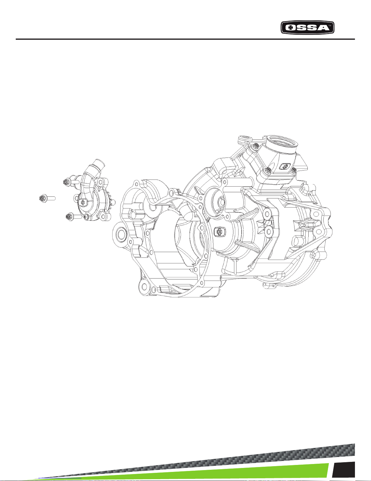
10- WATER PUMP
To remove the water pump, it is recommended to remove rst the rubber water hoses which are attatched to it with metal zipties.
Take out the 3 bolts that hold the pump onto the crankcase.
The water pump can be removed.
Page 18
18
ENGINE PARTS
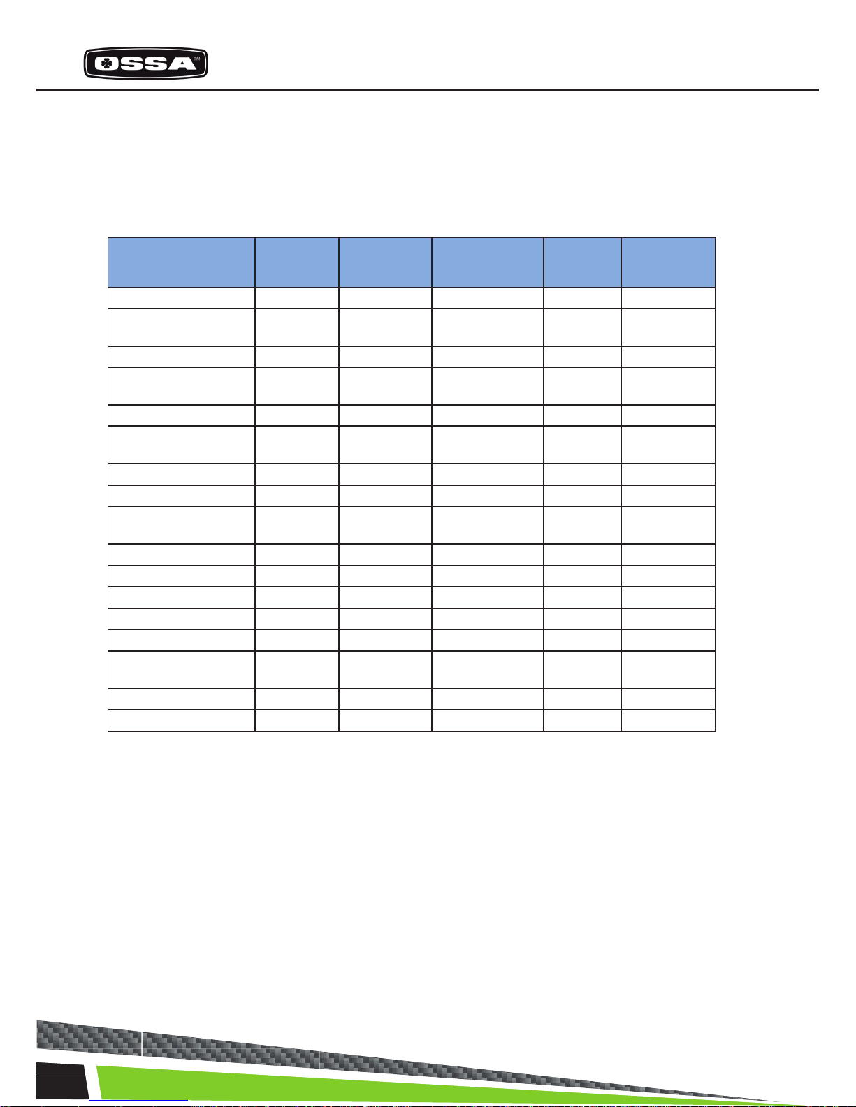
RECOMMENDED TORQUE VALUES FOR THE ENGINE BOLTS
PART TORQUE (N·m)
Spark plug 11
Ignition xing points 7-8
Clutch xing points 7-8
Cylinder bolts 25
Reed block 7-8
The 18 bolts for the clutch spring support plate 3-4
Water pump 7-8
Clutch cover 7-8
Rotor 40
Water tubing ngs 10
Ignion cover 7-8
Oil draining cap 12
Bolts for the kickstart pedal 12-13
Bolts for the gear shiing pedal 7-8
Cylinder head 8-9
Cylinder nut 25
Page 19
19
ENGINE ASSEMBLY AND DISASSEMBLY
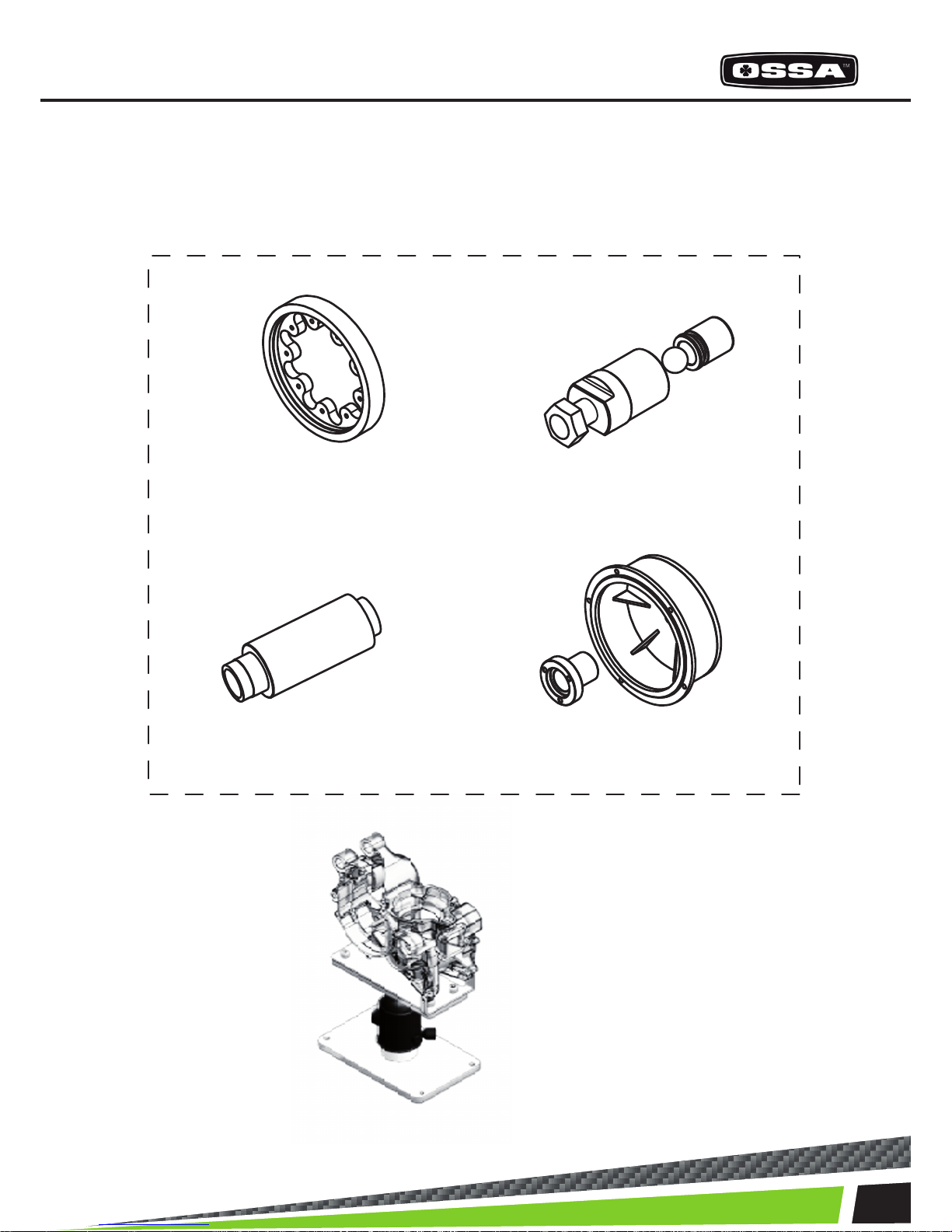
1499960211 OSSA WORKSHOP KIT
PRIMARY BEARING TOOL
CRANKSHAFT TOOL
CLUTCH POSITION TOOL
IGNITION & STATOR TOOL
1000960211
MOTOR SUPPORT TOOL
RECOMMENDED TOOLS FOR SERVICING THE OSSA TR280i ENGINE
Page 20
20
CYCLE PARTS
RECOMMENDED PERIODIC MAINTEINANCE
PART CHECK ADJUST REPLACE WASH
GREASE/
LUBE
Rear shock Every ride -- Every 2 years -- -Front fork Every ride When re-
quired
Every 2 years -- --
Front fork oil -- -- 60 hours -- -Brakes Every ride When re-
quired
If damaged -- --
Swingarm and linkage Every ride -- If damaged Every ride After washing
Secondary transmission
Every ride When re-
quired
If damaged Every ride After washing
Steering bearings
Every ride -- If damaged
--
After washing
Wheel bearings
30 hours -- If damaged
--
After washing
Disc brake rotors
Every ride When re-
quired
If damaged
-- --
Tyres
Every ride -- If damaged
-- --
Rims
Every ride -- If damaged Every ride
--
Spokes
Every ride 5 hours If damaged Every ride
--
Chassis
Every ride -- If damaged Every ride
--
Fuel tank
Every ride -- If damaged Every ride
--
Bolts, nuts
Every ride When re-
quired
If damaged Every ride
--
Crankcase protector
-- First ride If damaged Every ride
--
Protecve sckers
Every ride -- If damaged
-- --
Page 21
21
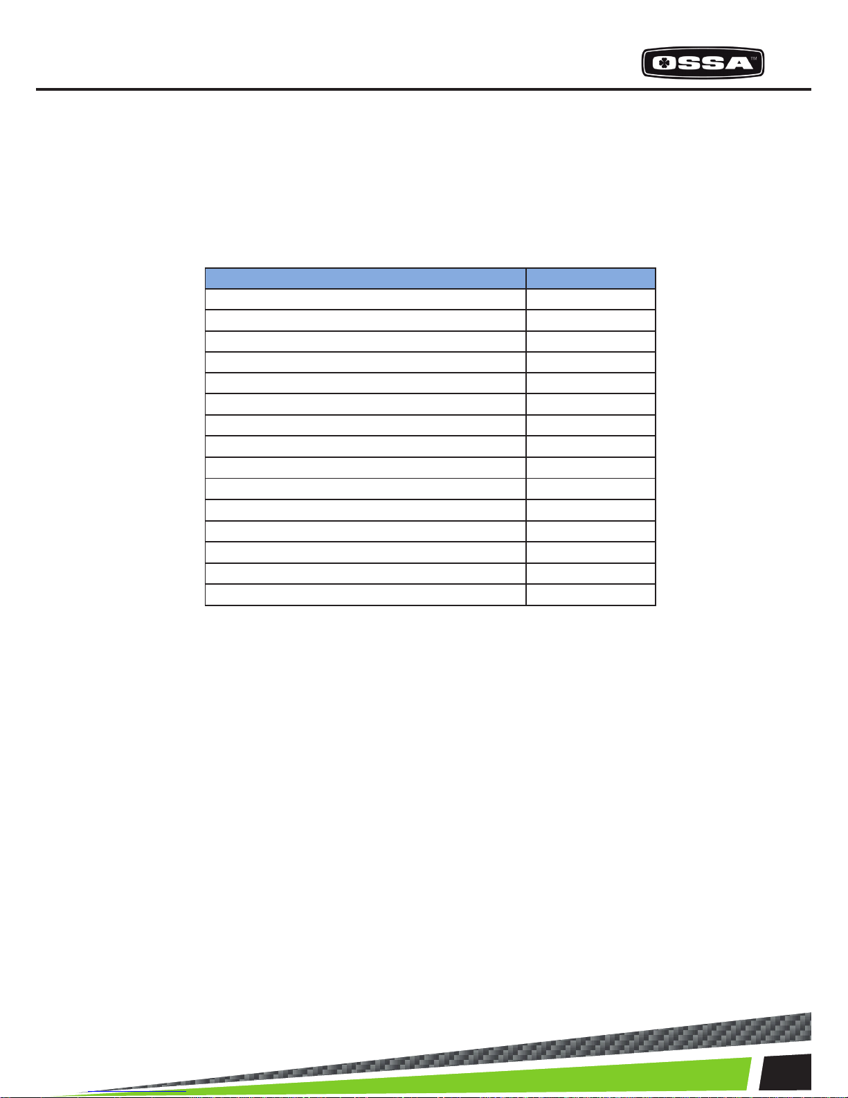
RECOMMENDED TORQUE VALUES FOR CYCLE PARTS
PART TORQUE (N·m)
Front Wheel axle 40-50
Swingarm to chassis xing points
70-80
Upper and lower joints from the shock absorber
40-50
Suspension linkage 40-50
Handblebars 18-25
Front brake and clutch levers 7-10
Radiator 7-10
Front mudguard support 7-10
Brake pedal 27-32
Exhaust 18-25
Rear wheel axle 80-90
Brake calipers 27-32
Exhaust pipe 27-32
Engine to chassis 18-25
Rear brake pump 7-10
Page 22

22
ELECTRICAL PARTS
Page 23

23
ESQUEMAS ELÉCTRICOS
Page 24

24
ELECTRICAL PARTS
16
15
17
21
24
11
27
2518
12
13
23
20
19
22
14
26
Page 25

25
ESQUEMAS ELÉCTRICOS
2
3
5
9
4
6
7
1
8
10
Page 26
26
ELECTRICAL PARTS
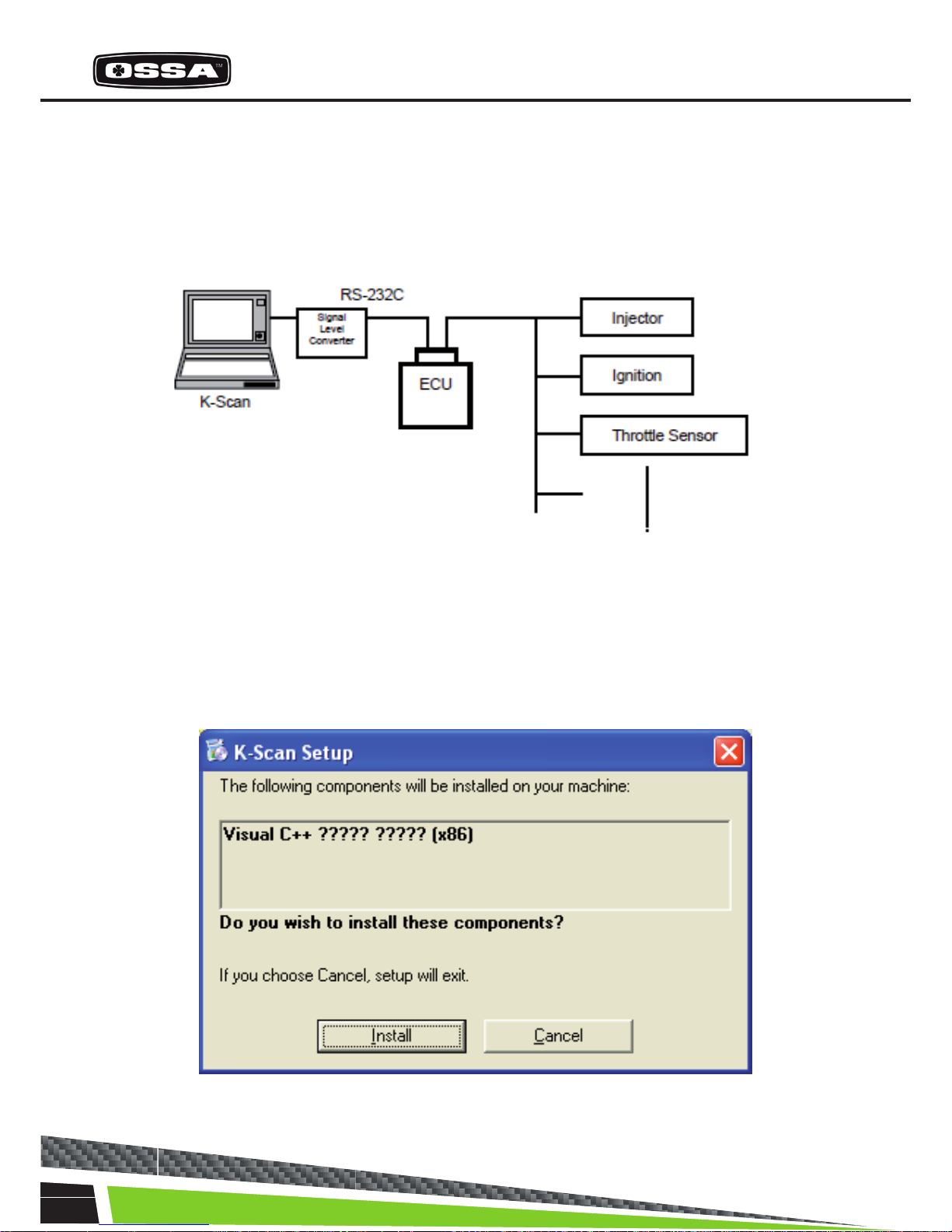
INTRODUCTION
This document describes the K-Scan System for PC.
Figure 1 shows the system composition. The K-Scan gives instructions of Active Test, gathers
and displays sensor values of the ECU.
Figure 1 System Composition Chart
INSTALLATION
1. Execute ‘setup.exe’ to show component setup wizard.
2. Click [Install] button in ‘component install’ screen to install ‘Visual C++ Runtime
Libraries(x86)’.
Page 27
27
KSCAN
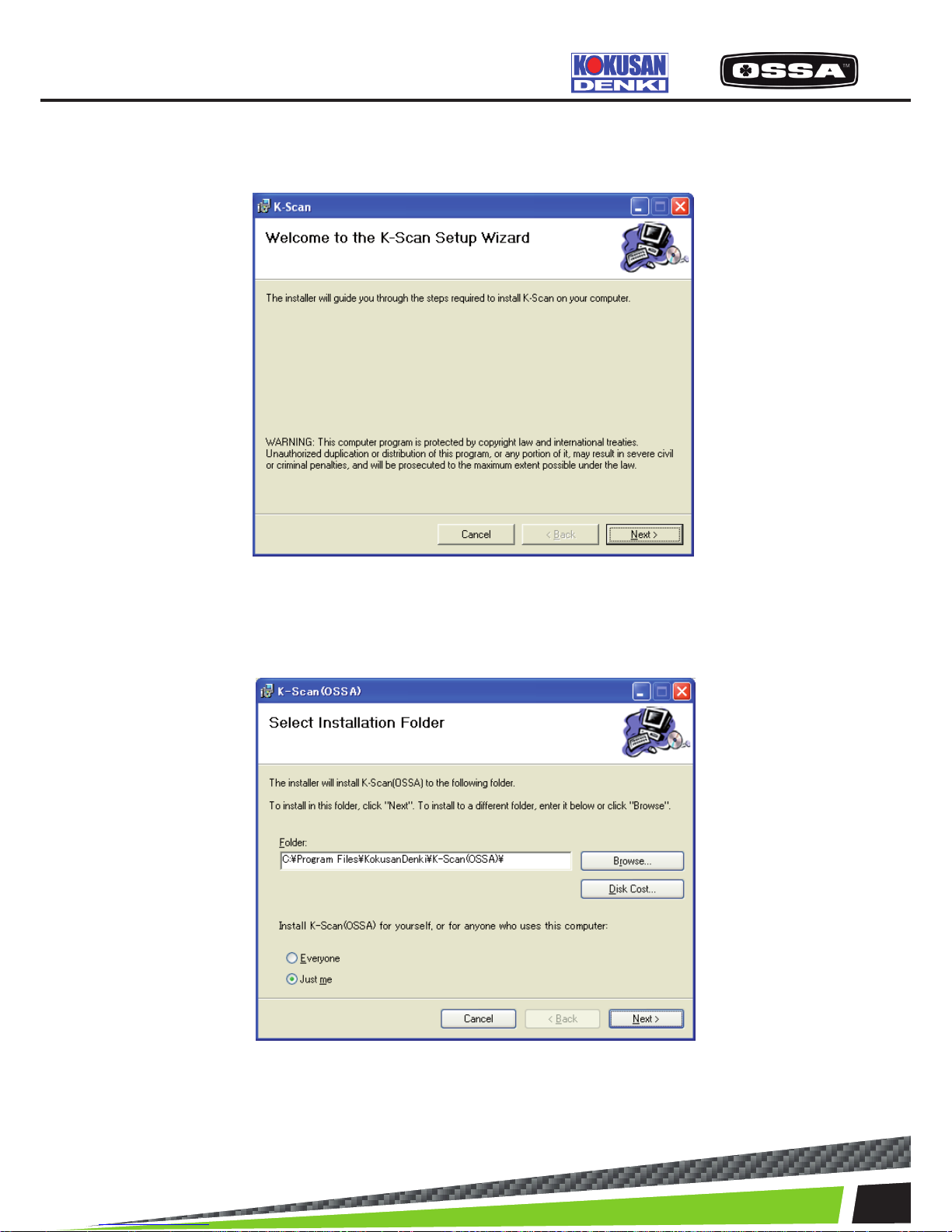
3. After installed the component, K-Scan setup wizard will be shown.
A) Click [Next] button in a ‘Welcome to the K-Scan Setup Wizard’ screen.
B) Select installation folder and user button in a ‘Select Installation Folder’ screen, then click [Next].
Page 28

28
ELECTRICAL PARTS
FOLDER COMPOSITION
[C:¥Program Files¥K-Scan(OSSA)]
K-Scan.exe ・・・Execute File
K-Scan.ini ・・・Main Setting File
GraphSetting.txt ・・・Graph Setting File
MakerCodeSetting.txt ・・・Maker Code Setting File A
ctiveTestSetting.txt ・・・Active Test Setting File
PCodeSetting.csv ・・・PCode Setting File
K-Scan.pdf ・・・User Manual(this document)
[¥Image]
English.bmp ・・・ American National Flag for the Language Screen.
Italy.bmp ・・・ Italian National Flag for the Language Screen
French.bmp ・・・ French National Flag for the Language Screen
German.bmp ・・・ German National Flag for the Language Screen
Spanish.bmp ・・・ Spanish National Flag for the Language Screen
Portuguese.bmp ・・・ Portuguese National Flag for the Language Screen
Logo.bmp ・・・ Logo Image for the Title Screen
ActiveTest_ID**.bmp ・・・ Active Test Images.
[¥Log] ・・・ Folder for Log
[¥DLL]
English.dll ・・・ DLL File for English
Italy.dll ・・・ DLL File for Italy
French.dll ・・・ DLL File for French
German.dll ・・・ DLL File for German
Spanish.dll ・・・ DLL File for Spanish
Portuguese.dll ・・・ DLL File for Portuguese
Page 29
29
KSCAN
SPECIFICATION FUNCTION
Title View
This is the start screen of the application.
Figure 2 Title View Screen
Data View Large
This screen is to display sensor values of 8 Data Items and 3 xed Data Items. 3 xed Data Items, Engine Temperature, Engine Speed and Intake Air Temperature, are displayed by meters and values. You
can select 8 Data Items using Select Data Items Dialog that is shown by clicking View Setting menu,
or toolbar button. If a selected Data Item does exist on ECU, ‘No Item’ will be shown. The application
remembers selected Data Items and save it to the setting le when you exit application. Engine Speed
meter is updated by 0.1 seconds and other Data Items are update by 0.5 seconds.
Figure 3 Data View Large Screen
Page 30
30
ELECTRICAL PARTS
1 Engine Temperature Display Data Item ・Engine Temperature・by meter and value.
2 Engine Speed Display Data Item ・Engine Speed・by meter and value.
3 Intake Air Temperature Display Data Item ・Intake Air Temperature・by meter and value.
4 Selected Data Item Display selected Data Item by value.
5 [Toolbar] View Setting button Show Select Data Item dialog to select 8 Data Items.
6 [Toolbar] Print button Print a screen image.
7 [Toolbar] Unit Switch button Switch unit mode.
8 When this screen is displayed When the ECU is not connected, the ECU connection will be
started. If failed to connect to the ECU, the message 7 will
be shown(See ・-・Message List).
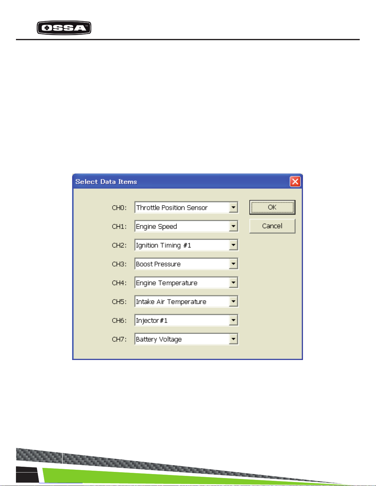
SELECT DATA ITEMS
This dialog is to select 8 Data Items.
Figure 4 Select Data Items Dialog
1 CH0 - CH7 combo box Select a Data Item from list. The list is created when this dialog is
created.
2 [OK] button Save selection of Data Items and close this dialog.
3 [Cancel] button Cancel selection of Data Items and close this dialog.
Page 31
31
KSCAN
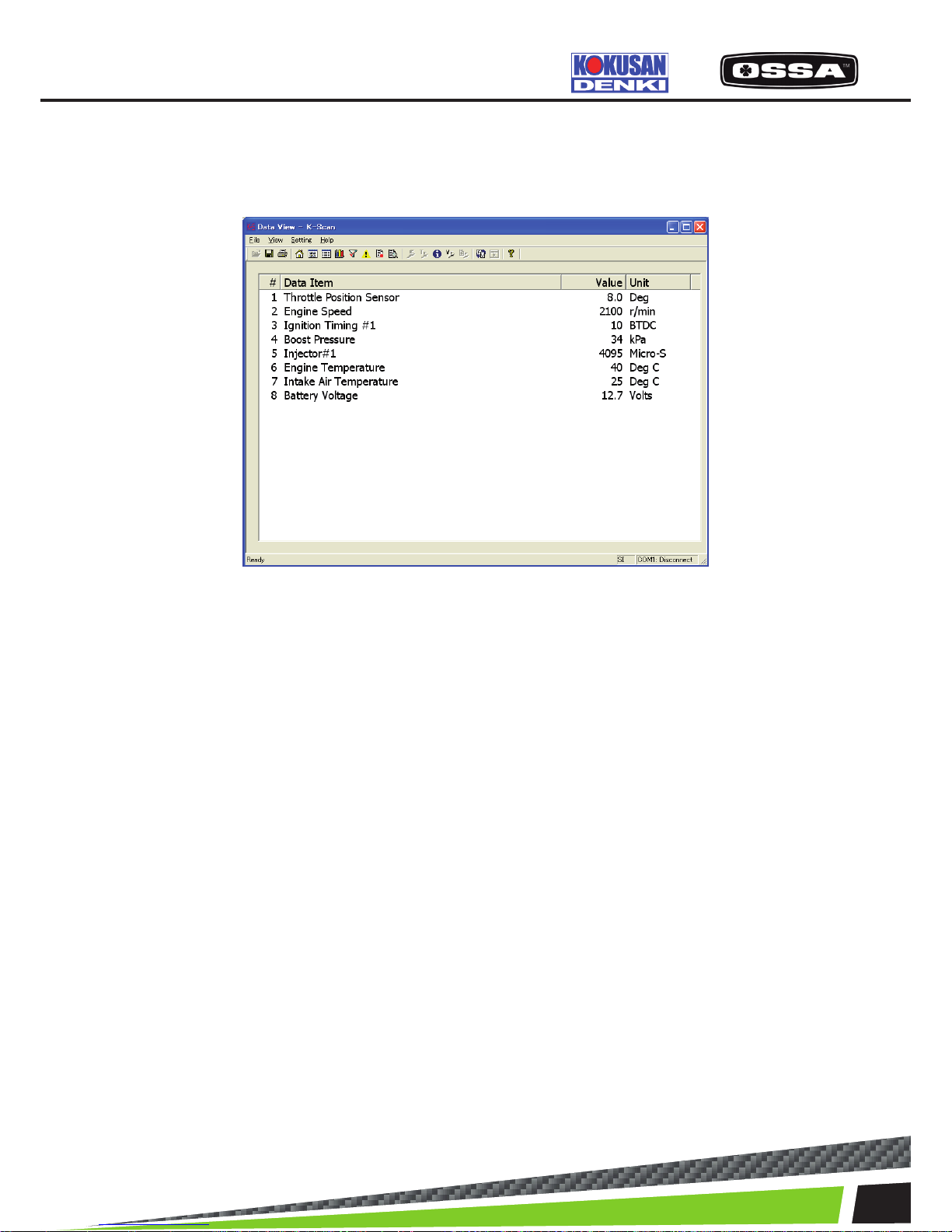
DATA VIEW
This screen is to display sensor values of Data Items. Sensor values are updated by every 0.5 seconds.
Figure 5 Data View Screen
1 List box Display all Data Items that the ECU corresponds.
#: Index
Data Item: name of each Data Item.
Value: sensor values of each Data Item.
Unit: units of each Data Item.
2 [Toolbar] Save button Save a screen data as csv format le.
3 [Toolbar] Print button Print a screen data.
4 [Toolbar] Unit Switch button Switch unit mode.
5 When this screen is displayed When the ECU is not connected, the ECU connectionwill be
started. If failed to connect to the ECU, the message 7 will
be shown.
Page 32
32
ELECTRICAL PARTS
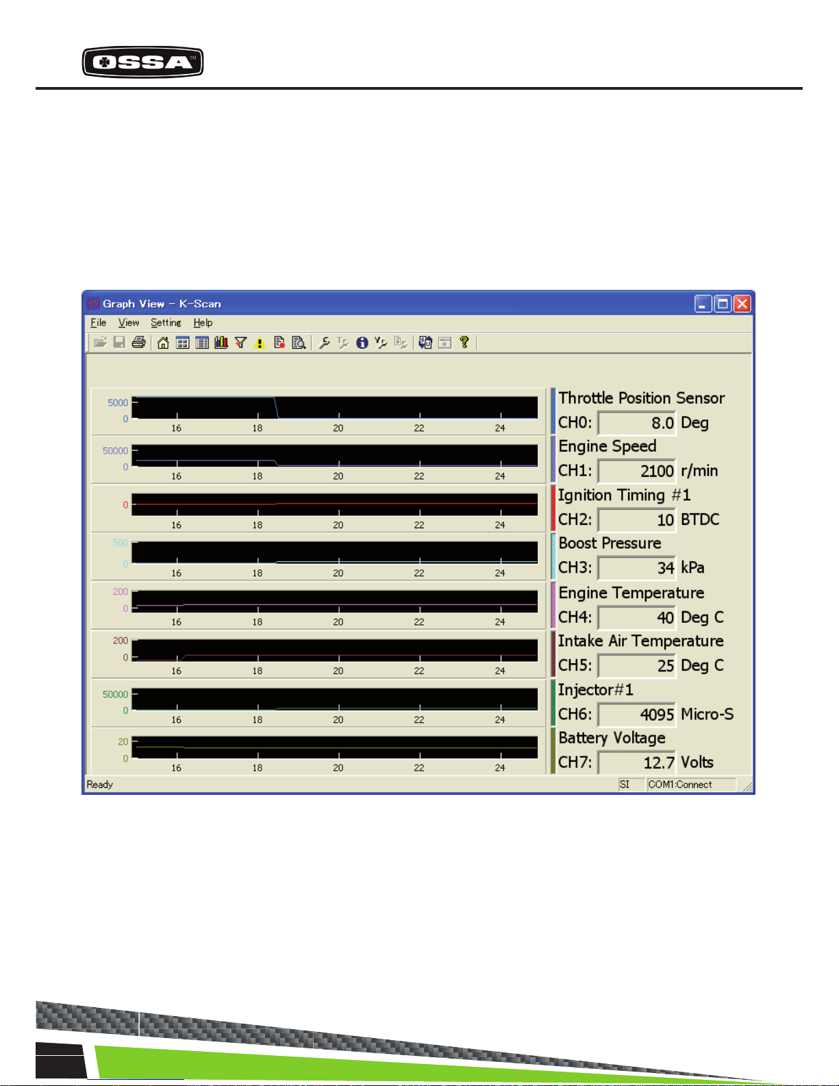
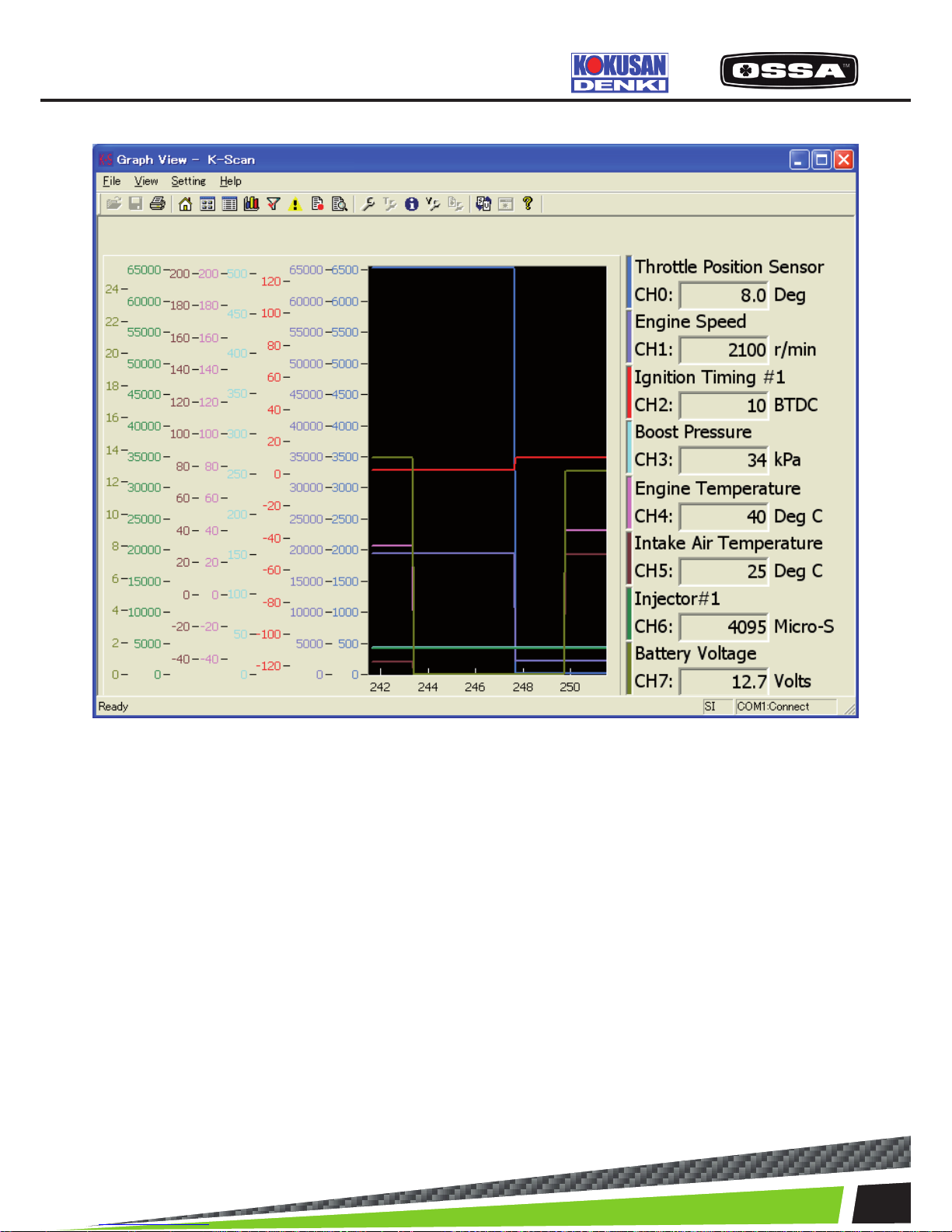
GRAPH VIEW
This function is to display sensor values by graphs. Graphs are updated every 0.1 seconds. You can
select 8 Data Items using Graph Setting Dialog that is shown by clicking ‘View Setting’ menu, or toolbar
button. You can also select a type of graph, parallel and overlay, using Graph Setting Dialog. If you select less than 8 Data Items and parallel view mode, size of graphs will be automatically adjusted. Figure
6 Graph View(Parallel) Screen
Page 33
33
Figure 7 Graph View(Overlay) Screen
1 Graph Display sensor values of Data Items by graphs.
These graphs keep sensor values for 10 seconds.
Leftpart of the graph will be discarded and the other
partswill be shifted to the left after 10 seconds.
These graphswill be cleared when you move to other
screens.
2 Selected Data Item Display a current value of Data Item.
3 [Toolbar] Print Print a screen image.
4 [Toolbar] View Setting button Show Graph Setting dialog.
5 [Toolbar] Unit Switch button Switch unit mode.
6 When this screen is displayed When the ECU is not connected, the ECU
connectionwill be started. If failed to connect to the
ECU, themessage 7 will be shown
KSCAN
Page 34
34
ELECTRICAL PARTS
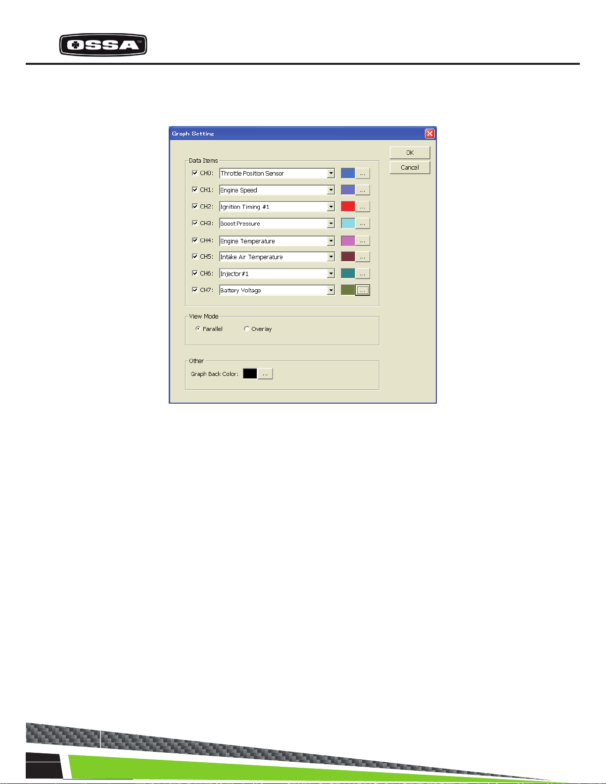
Graph Setting
This dialog is used to set graph parameter.
Figure 8 Graph Setting Dialog
1 Data Items Check box Set a channel to be displayed or not. Checked channels will
be displayed on the graph.
2 Data Items Combo box Select Data Item of the channel.
3 Data Items […] button Select plot color of the channel.
4 View Mode Select a view mode. Parallel: Each channel will be displayed
in a separategraph. Overlay: All channels will be displayed in
one graph.
5 Graph Back Color Select a back color of a plot area.
6 [OK] button Save settings and close this dialog.
7 [Cancel] button Cancel settings and close this dialog.
Page 35
35
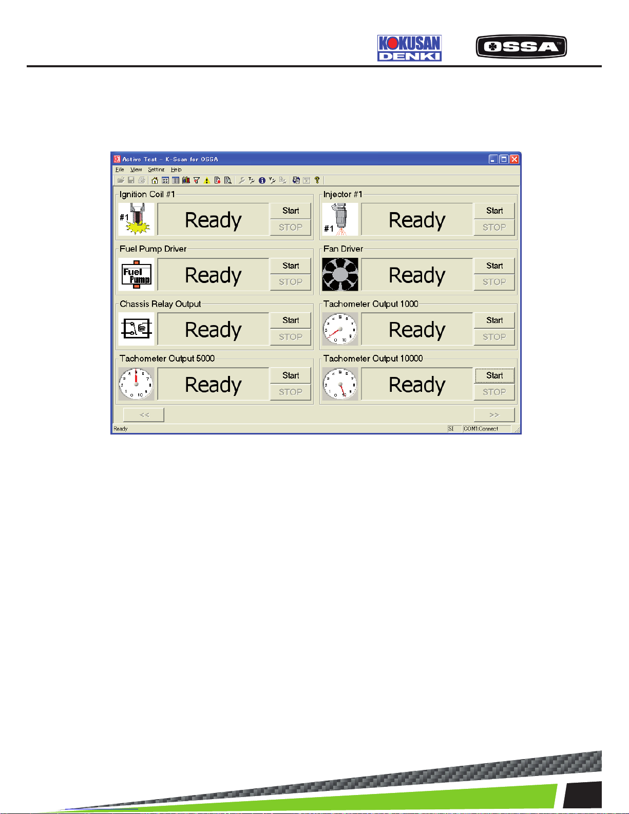
ACTIVE TEST
This function is to execute Active Test items. There are 8 Data Items in one page, and you can scroll
page by clicking [<<] and [>>] buttons. You cannot click any button during Active Test, except [Stop]
button.
Figure 9 Active Test Screen
1 Active Test Item There are 8 Data Items in one page, and you can scroll
page to display all test items by clicking ‘<<’ and ‘>>’
buttons.
2 Icon Display Active Test image.
3 State text box Display operational information.
-’Ready’- Active Test has not been done.
-‘Finish’- Active Test has already been done.
-‘Running…’ or ‘XXX Sec’ -Active Test is running now.
4 When Active Test Error is occurred If failed to connect to the ECU while running ActiveTest, the
message 7 will be shown and Active Test state becomes
‘Ready’.
5 [Start] button Start Active Test.
6 [Stop] button Stop Active Test.
7 [<<] button Move to previous page.
8 [>>] button Move to next page.
9 When this screen is displayed When the ECU is not connected, the ECU connectionwill be
started. If failed to connect to the ECU, themessage 7 will be
shown.
KSCAN
Page 36
36
ELECTRICAL PARTS
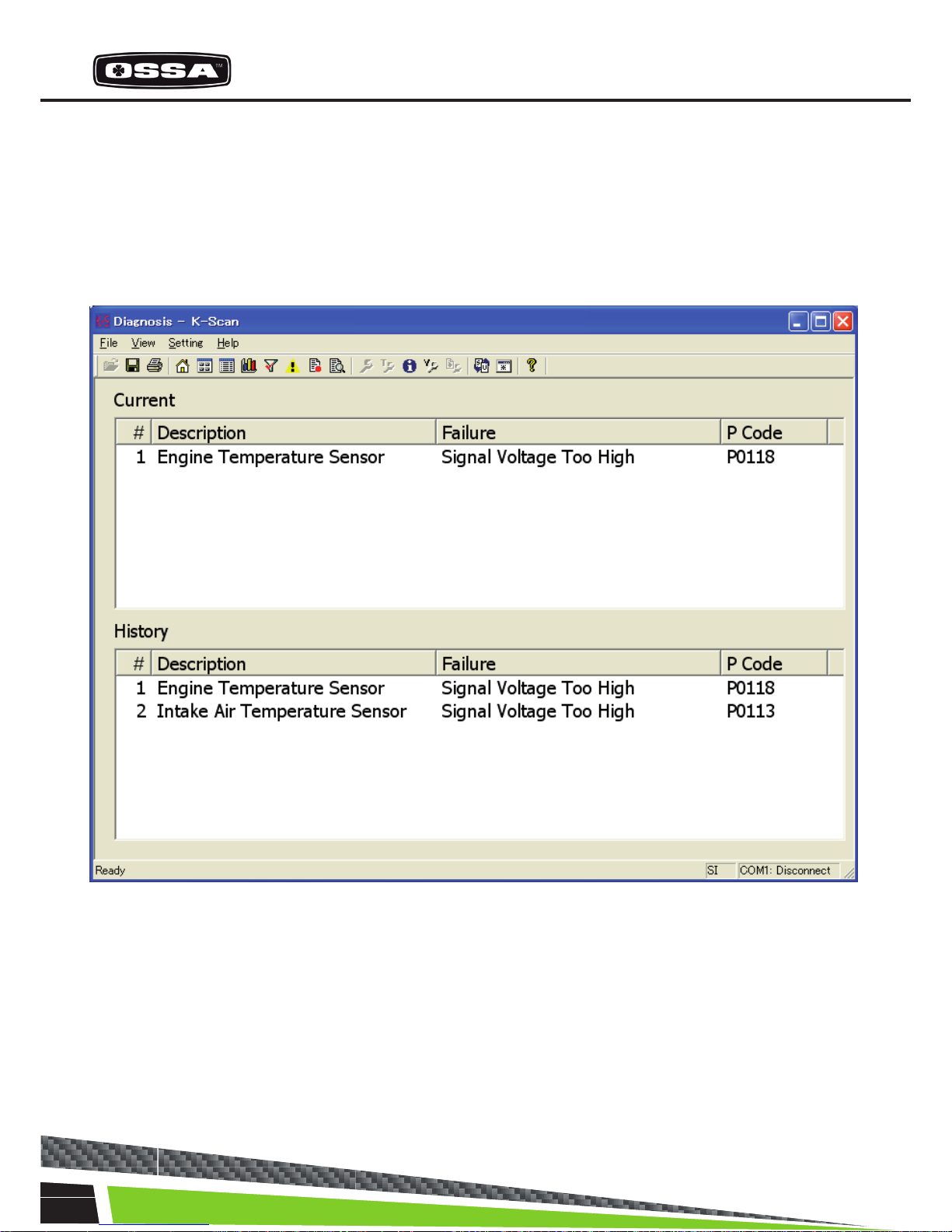
Diagnosis
This function is to display DTC (Data Trouble Code) of the ECU. This screen displays DTC errors by 2
list-boxes, to show two types of DTC error, current error and historic error.
Figure 10 Diagnosis Screen
Page 37

37
1 Current list box Display current DTC errors.
#: Index
Description: DTC Description
Failure Type: Failure Type name
P Code: P Code
2 History list box Display historic DTC errors.
#: Index
Description: DTC description.
Failure Type: Failure Type name
P Code : P Code
3 [Toolbar] Save button Save a screen data as csv format le.
4 [Toolbar] Print button Print a screen data.
5 [Toolbar] History Clear Clear historic DTC errors.
When you clicked the button, the Message 14 will
beshown.
If you select ‘Yes’button, historic errors are cleared. But i
f the application failed to clear historic errors, the Message
15 will beshown.
6 When this screen is displayed When the ECU is not connected, the ECU connection will
be started. If failed to connect to the ECU, theMessage 7 will
be shown.
KSCAN
Page 38
38
ELECTRICAL PARTS
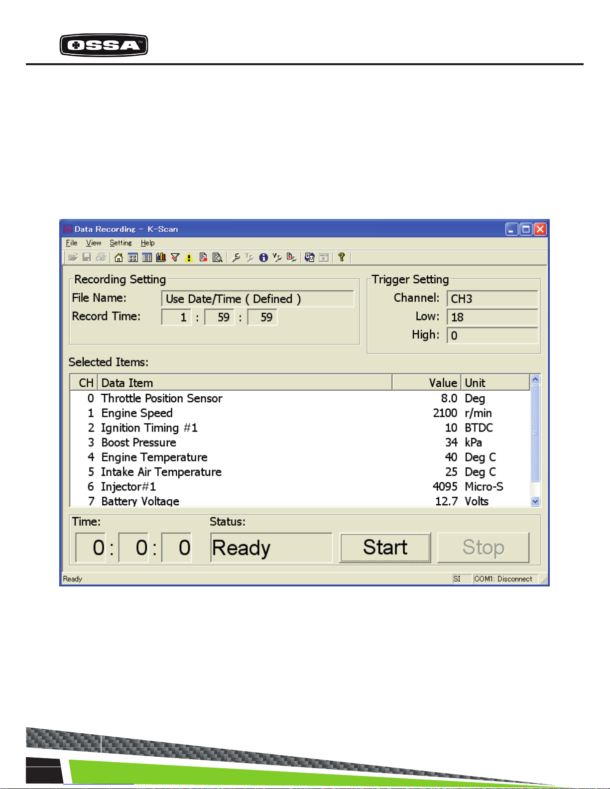
DATA RECORDING
This function is to record sensor values of 8 Data Items. You can select 8 Data Items using Select Data
Items Dialog that is shown by clicking ‘View Setting’ menu or toolbar button. You can also give the le
name, recording time and trigger setting using Data Recording Setting Dialog that is shown by clicking
Data Recording Setting menu or toolbar button.
If there is no trigger, the recording will be started after the start button clicked. Else if there is a trigger,
the recording will be started after the trigger taken. After nishing the recording, the Message17 will be
shown.
Figure 11 Data Recording Screen
Page 39

39
1 List box Display 8 Data Items.
CH: Index of Channel.
Data Item: name of each Data Item.
Value: sensor values of each Data Item.
Unit: units of each Data Item.
2 File Name Display a lename.
When ‘Use Date/Time’ is displayed, the lename
is created by date and time before start recording.
(A lename will be given such as ‘LOG2007_
Jan_01_12_00_00.csv’)
3 Record Time Display a record time.
If the record time is ’00:00:00’, it will works as
‘ManualStop Mode’. The recording will be continued
till the Stopbutton is clicked.
4 Channel Display a selected trigger channel.
If there is no trigger, blank will be displayed.
5 Low Display the limit value of low-level trigger.
When sensor value of the Data Item becomes less
than the limit value, the recording will be started.
6 High Display the limit value of high-level trigger.
When sensor value of the Data Item becomes more
equal than the limit value, the recording will be star
ted.
7 Time Display an elapsed time of the recording.
8 State Display three recording state.
1. Ready Before click a start button.
2. Waiting Waiting a trigger.
3. Recording Recording sensor values.
9 [Toolbar] View Setting button Show Select Data Items Dialog.
10[Toolbar] Recording Setting button Show Data Recording Setting Dialog.
11 [Start] button Start recording sensor values. If there is a trigger,
‘Waiting’ is displayed. After thetrigger is taken, ‘Re
cording’ will be displayed and therecoding will be
started.
12 [Stop] button Stop recording or waiting.
13 When this screen is displayed When the ECU is not connected, the ECU connec
tionwill be started. If failed to connect to the ECU, the
Message 7 will be shown.
KSCAN
Page 40

40
ELECTRICAL PARTS
SELECT DATA ITEMS
This dialog is to select 8 Data Items.
Figure 12 Select Data Items Dialog
1 CH0 - CH7 combo box Select a Data Item from a list.
The list is created when this dialog is created.
2 [OK] button Save selection of Data Items and close this dialog.
3 [Cancel] button Cancel selection of Data Items and close this dialog.
Page 41
41
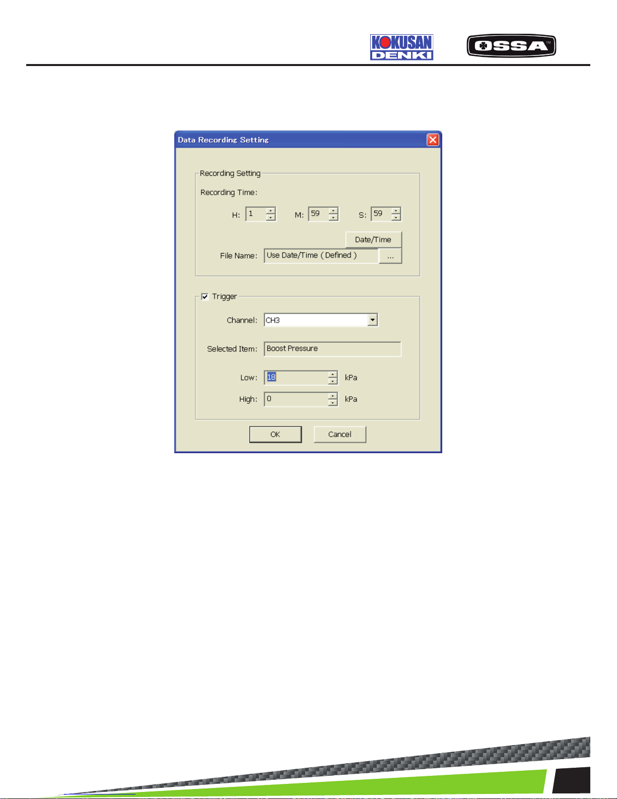
DATA RECORDING SETTING
This dialog is used to set Data Recording settings.
Figure 13 Data Recording Setting Dialog
1 Recording Time Set the record time (H: hour M: minute S: second) byspin
controls.
2 File Name Display a le name.
3 [Date/Time] button Set the lename by date and time. ‘Use Date/Time’ will be
shown.
4 […] button Show a dialog to set the le name.
5 Trigger check box Set the trigger mode enable or not.
6 Channel Set a channel to a trigger. It is possible to select ‘CH0’ –
‘CH7’.
7 Selected Item Display the Data Item names of the selected channel.
8 Low Set the low-level trigger value by a spin control. If the value
is 0, the trigger will be ignored.
9 High Set the high-level trigger value by a spin control. If the value
is 0, the trigger will be ignored.
10 [OK] button Save settings and close this dialog.
11 [Cancel] button Cancel settings and close this dialog.
KSCAN
Page 42
42
ELECTRICAL PARTS
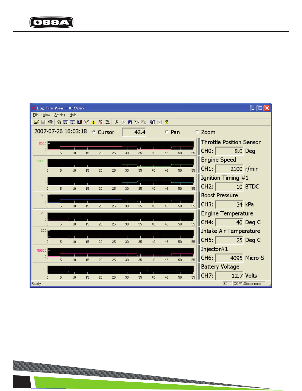
LOG FILE VIEW
This function is to display graphs of sensor values in a log le created by Data Recording function of
this application or K-Scan(PDA) application. You can open a log le using common dialog that is shown
by clicking ‘View Setting’ menu, or toolbar button. You can also select a type of graph, parallel or overlay, using Graph Setting Dialog. If you select less than 8 Data Items and parallel view mode, size of
graphs will be automatically adjusted.
Figure 14 Log File View(Parallel) Screen
Page 43
43
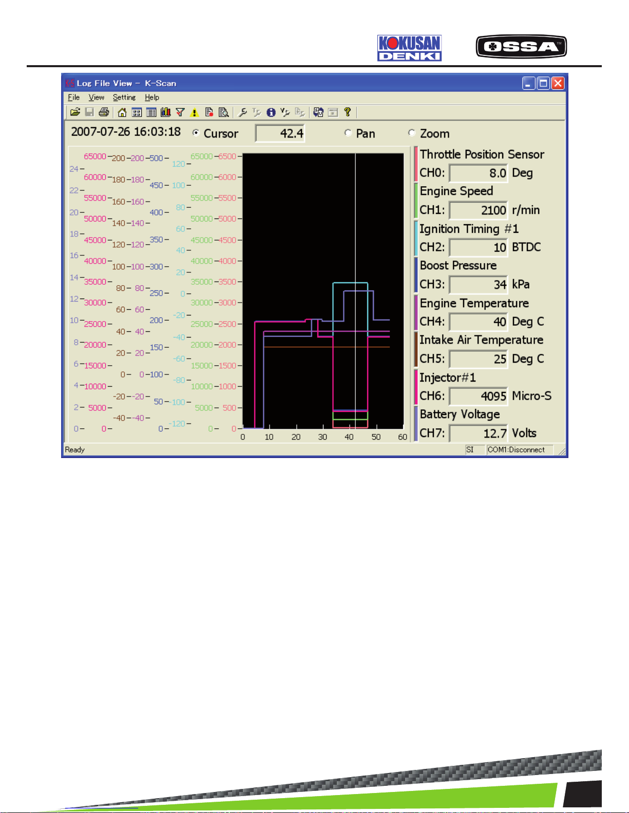
Figure 15 Log File View(Overlay) Screen
1 Date/Time Display date and time in a log le.
2 Graph Display sensor values of Data Items.
There is no limitation to the x-axis that means time
span.
3 Operation Mode Set mouse operation mode on graphs.
When [Zoom] is selected,plot areas of graphs will be initia
led.
Cursor: You can drag a cursor to display the sensor values
at the cursor position. A passed time at the cursor position
will be displayed in the text box.
Pan: You can scroll graphs by dragging a plot area.
Zoom: You can drag a plot area to zoom in plot area.
You can also click a plot area with [Shift] key to zoom
out.
4 Selected Data Item Display a value of Data Item at the cursor position.
5 [Toolbar] View Setting button Show Log File View Setting Dialog.
6 [Toolbar] Print button Print a screen image.
7 [Toolbar] Open Log File button Show common dialog to open a log le.
KSCAN
Page 44

44
ELECTRICAL PARTS
Log File View Setting
This dialog is used to set graph parameter.
Figure 16 Log File View Setting Dialog
1 Data Items Check box Set a channel to be displayed or not.
Checked channelsare displayed by graph.
2 Data Items Combo box Select Data Item of a channel.
3 Data Items […] button Select a plot color of a channel.
4 View Mode Select a view mode.
Parallel: Each channel is displayed in a separate
graph.
Overlay: All channels are displayed in one graph.
5 Graph Back Color Select a back color of graphs.
6 Graph Cursor Color Select a cursor color of graphs.
7 [OK] button Save settings and close this dialog.
8 [Cancel] button Cancel settings and close this dialog.
Page 45

45
OPERATING TIME VIEW
This dialog is used to set Operating time view.
Figure 17 Operating time View
1 Total operating time Display the Total operating time.
Can not be cleared.
2 Operating time 1 Display the Operating time 1.
3 [Clear] button
Operating time 1 Clear Clear the Operation time 1.
4 Operating time 2 Display the Operating time 2.
5 [Clear] button Clear the Operation time 2.
Operating time 2 Clear
6 Operating time 3 Display the Operating time 3.
7 [Clear] button Clear the Operation time 3.
Operating time 3 Clear
8 [Close] button Close this dialog.
KSCAN
Page 46
46
ELECTRICAL PARTS
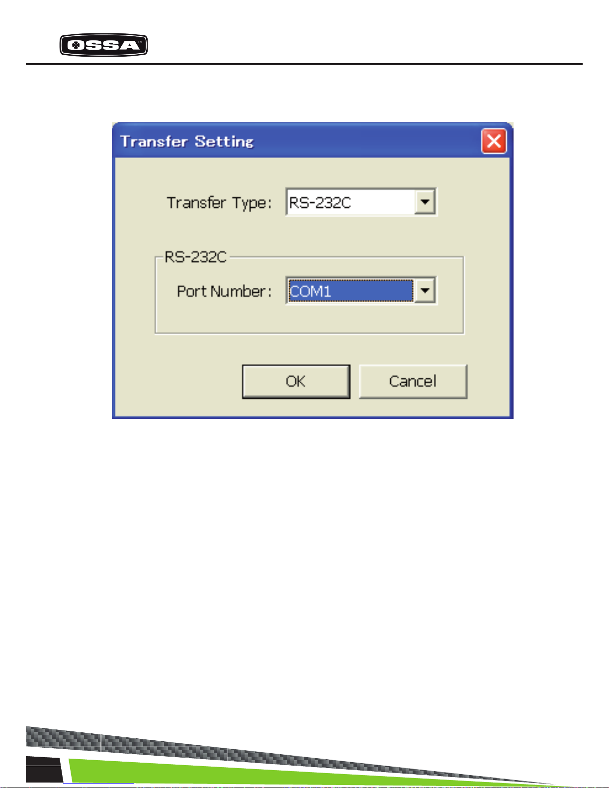
Transfer Setting
This dialog is used to set the transfer.
Figure 18 Transfer Setting Dialog
1 Transfer Type combo box Set the transfer type. You can select the transfer
type only ‘RS232C’ in this version.
2 RS232C Port Number combo box Set the COM port. It is possible to select COM port
from ‘COM1’ - ‘COM10’and ’Auto’. If ‘Auto’ is selec
ted, COM port is searchedfrom ‘COM1’ to ‘COM10’
when the Back button is clicked.
3 [OK] button Check ECU connection. If succeeded to connect to
the ECU, close this dialog. If failed to connect to the
ECU,the Message 13 will be shown.
4 [Cancel] button Cancel settings and close this dialog.
Page 47
47
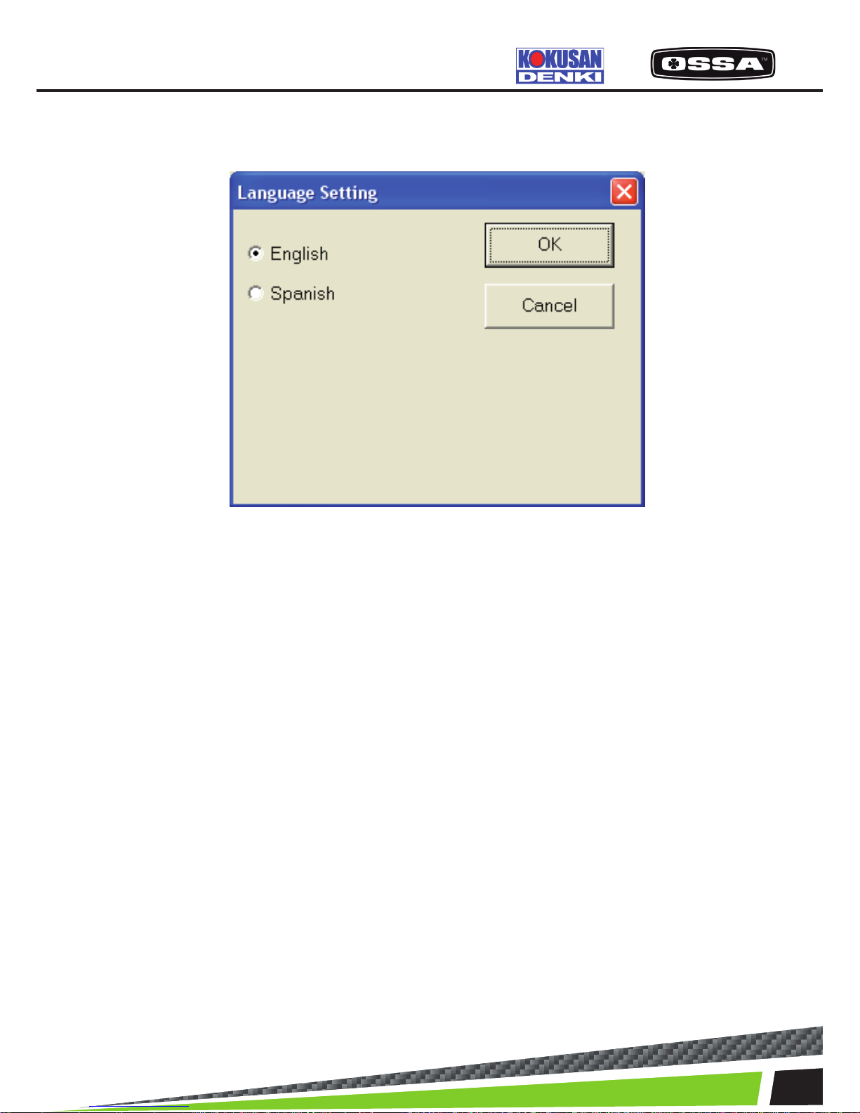
Language Setting
This dialog is used to select a language.
Figure 19 Language Setting Dialog
1 English Select English as the language setting.
2 Spanish Select Spanish as the language setting.
3 [OK] button Save settings and close this dialog.
4 [Cancel] button Cancel settings and close this dialog.
KSCAN
Page 48
48
ELECTRICAL PARTS
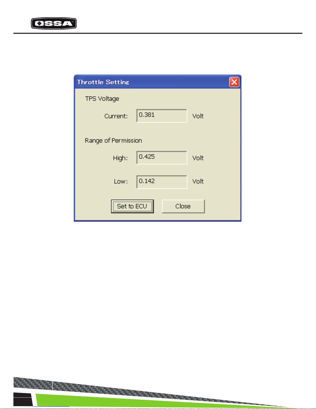
Throttle Setting
This function is to set a TPS (Throttle Position Sensor) voltage at closing point to the ECU. In order to
adjust differences of throttle body (TH/B) on a vehicle, it is possible to let the ECU to learn the TPS
voltage at the metal touch position of throttle buttery.
Figure 20 Throttle Setting Dialog
1 TPS Voltage Current Display current TPC voltage. If the voltage is not within a
normal range, it will bedisplayed in red.
2 Range of permission High Display upper bound voltage within the normal range.
3 Range of permission Low Display lower bound voltage within the normal range.
4 Set to ECU button Set the TPS voltage to the ECU. When you clicked the
button, the Message 19 will beshown.
If you select ‘Yes’ button, current TPS Voltage will be setto
the ECU. If it is succeeded to set, the Message 20 willbe
shown. But if it is failedto set, one of the Message 21-28 will
be shown.
5 [Close] button Close this dialog.
Page 49
49
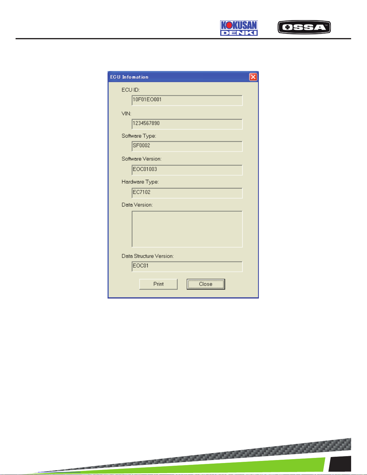
ECU INFORMATION
This dialog is used to see ECU information.
Figure 21 ECU Information Dialog
1 ECU ID Display the ECU ID (Serial Number).
2 VIN Display a VIN (Vehicle Identication Number) code
of the ECU.
3 Software Type Display a software type of the ECU.
4 Software Version Display a hardware version of the ECU.
5 Hardware Type Display a hardware type of the ECU.
6 Data Version Display a data version of the ECU.
7 Data Structure Version Display a data structure version of the ECU.
8 [Print] button Print ECU information data.
9 [OK] button Close this dialog.
KSCAN
Page 50
50
ELECTRICAL PARTS
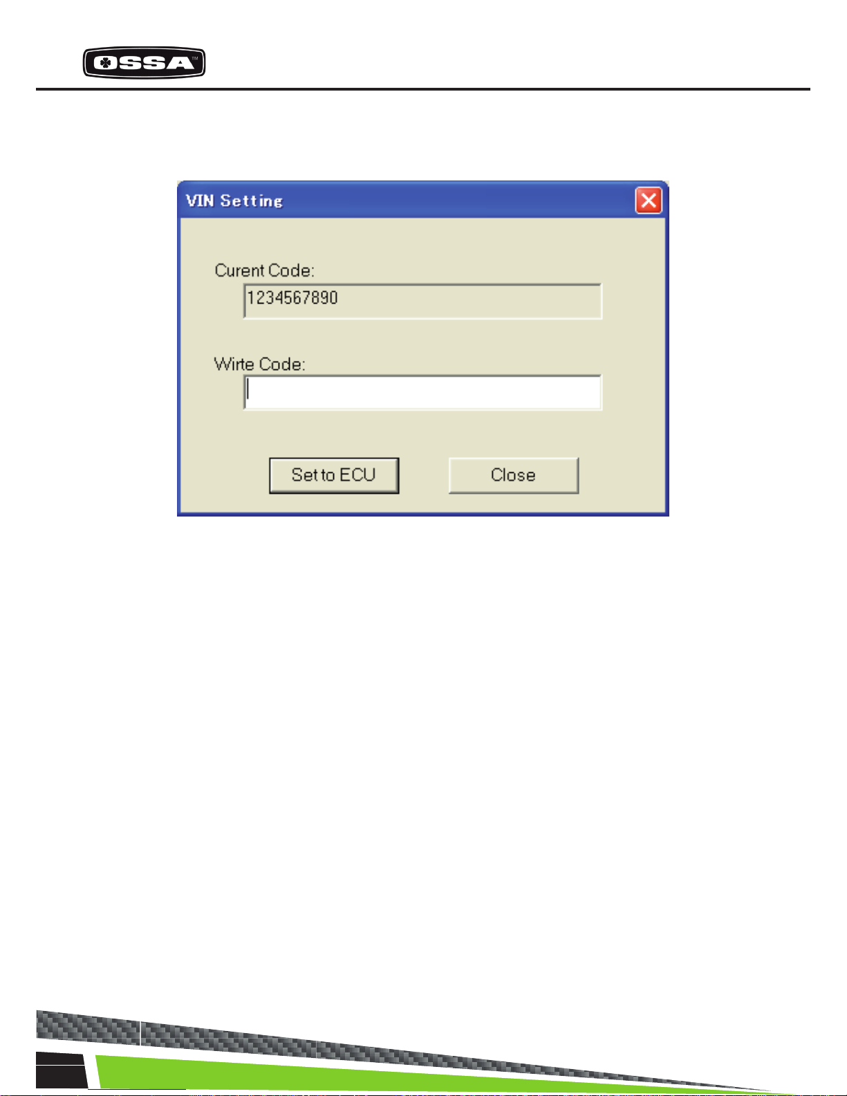
VIN SETTINGS
This dialog is used to set a VIN code to the ECU.
Figure 22 VIN Setting Dialog
1 Current Code Display a VIN (Vehicle Identication Number) code ofthe ECU.
2 Write Code text box Input a VIN code to be set to the ECU.
3 [Set to ECU] button Set inputted VIN code to the ECU. When you clicked the button,
the Message 29 will beshown. If you select ‘Yes’ button, the VIN
code will be set to theECU. If it is succeeded to set, Current Code
will beupdated. But if it is failed to set, the Message 30 will be
shown.
4 [Close] button Close this dialog.
Page 51

51
About K-Scan
This dialog is used to display version information.
Figure 23 About K-Scan Dialog
1 [OK] button Close this dialog.
KSCAN
Page 52

52
ELECTRICAL PARTS
# Message Type Screen Case
1 Cannot open 'K-Scan.txt'. OK Title ‘K-Scan.txt’ does not exist.
2 Cannot open 'GraphSetting.txt'. OK Title ‘GraphSetting.txt’ does not
exist.
3 Cannot open 'PCodeSetting.csv'. OK Title ‘PCodeSetting.csv’ does not
exist.
4 Cannot open OK Title 'MakerCodeSetting.txt' does not
‘MakerCodeSetting.txt’ exist.
5 Cannot open ' OK Title 'ActiveTestSetting.csv' does not
ActiveTestSetting.csv’. exist.
6 Cannot load the language DLL. OK Title The DLL le of selected langua ge does not exist.
7 Cannot connect to the ECU. OK Transfer The application cannot connect
Data View to the ECU.
Data View Large
Graph View
Diagnosis
Active Test
Data Recording
Throttle Setting
ECU Information
VIN Setting
Operating time
8 The ECU connection is OK Transfer Data The ECU connection
reconnected. View Data is reconnected.
View Large
Graph View
Diagnosis
Active Test
Data Recording
Throttle Setting
ECU Information
VIN Setting
Operating time
9 The ECU returned OK Transfer The ECU returned invalid
invalid maker code. Data View maker code that is supported
Data View Large by ‘MakerCodeSetting.txt’.
Graph View
Diagnosis
Active Test
Data Recording
Throttle Setting
ECU Information
VIN Setting
Operating time
MESSAGE LIST
Page 53

53
10 The ECU returned invalid code.
Please reset the ECU. OK Diagnosis When the ECU returned invalid
code.
11 Push the stop button, and try again. OK Graph View When you click the
Active Test Running button to Switch Screen
Data Recording while each process of
Screens is running.
12 This version does not OK The language When you select except
support this language. English.
13 Cannot connect to the ECU! OK The transfer The application cannot
connect to the ECU with
the setting when you
click the back button.
14 Would you like to clear YESNO Diagnosis When you click the
all historic errors? History Clear button.
15 Cannot clear historic errors. OK Diagnosis The application failed to clear
the ‘Historic Error’.
16 The recording error occurred. OK Data Recording The application failed to
record data.
17 The recording was nished. OK Data Recording The recording was
nished normally.
18 Cannot open the recording le. OK Data Recording The application cannot
open the recording le.
19 Have you set a throttle buttery
to the metal touch position?
Is the range of the current voltage normal? YESNO Throttle Setting When you click the Set
to ECUbutton.
20 Setting is succeeded. OK Throttle Setting When the ECU returned
normal code.
21 TPS voltage is out of range. OK Throttle Setting When the ECU returned
this error code.
22 TPS Sensor Error. OK Throttle Setting When the ECU returned
this error code.
23 TPS Sensor Power Error. OK Throttle Setting When the ECU returned
this error code.
24 Engine is running. OK Throttle Setting When the ECU returned
this error code.
25 Out of Battery. OK Throttle Setting When the ECU returned
this error code.
26 There is no software in the ECU. OK Throttle Setting When the ECU returned
this error code.
27 Unexpected error occurred. OK Throttle Setting When the ECU returned
this error code.
28 This function is not supported by the ECU. OK Throttle Setting When the ECU returned
Operating time this error code.
KSCAN
Page 54

54
ELECTRICAL PARTS
29 Would you like to write VIN code? YESNO VIN Setting When you click the Set
to ECU button.
30 Cannot write VIN Code. OK VIN Setting When the application
failed to write the ‘Histo
ric Error’.
31 Cannot save screen data. OK Data View When the application
Diagnosis failed to save screen
data.
32 Cannot open selected log le. OK Log File View When the application
failed to open a log
le.
33 Cannot print screen data. OK ECU Information When the application
failed to print screen
data.
34 Cannot open ‘K-Scan.pdf’. OK Help When the application
failed to open the ‘K-
Scan.pdf’.
Page 55

55
KSCAN
Page 56
56
ELECTRICAL PARTS
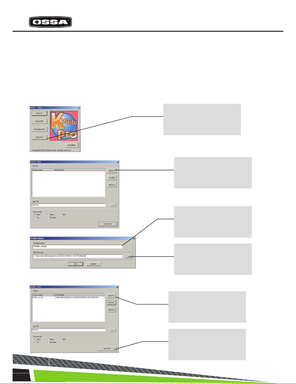
QUICK SOFTWARE UPDATING
1.First of all disconnect the Capacitor Unit wires (under the headlight mask) and connect to a 12V
Battery.
2.Execute the [Kwrite Pro] software.
3.Register the “kds le” in [Kwrite Pro].
Note: this process is necessary to execute only once for each update version.
Step 1
Start [Kwrite Pro] and click on
“KCM”
Step 2
Click on “Add”, and set up the
information path of the kds le.
Step 3
Input the information on the
le (i.e. Update date)
Step 4
Click here and select the .kds
le.
The registration of the .kds le
was completed by the abovementioned operation
Step 5
Click on “Back”
Page 57

57
4. Write/-Update the .kds le in ECU.
Step 1
Click on “Pro”
Step 3
The .dks le registered by Process 2 is displayed. Select the
le that executes writing.
Step 2
Click on “Edit” only the
rst time.
Step 4
Click on “Start Download”.
Step 5
Click on “Yes”
KWRITE PRO
Page 58
58
ELECTRICAL PARTS
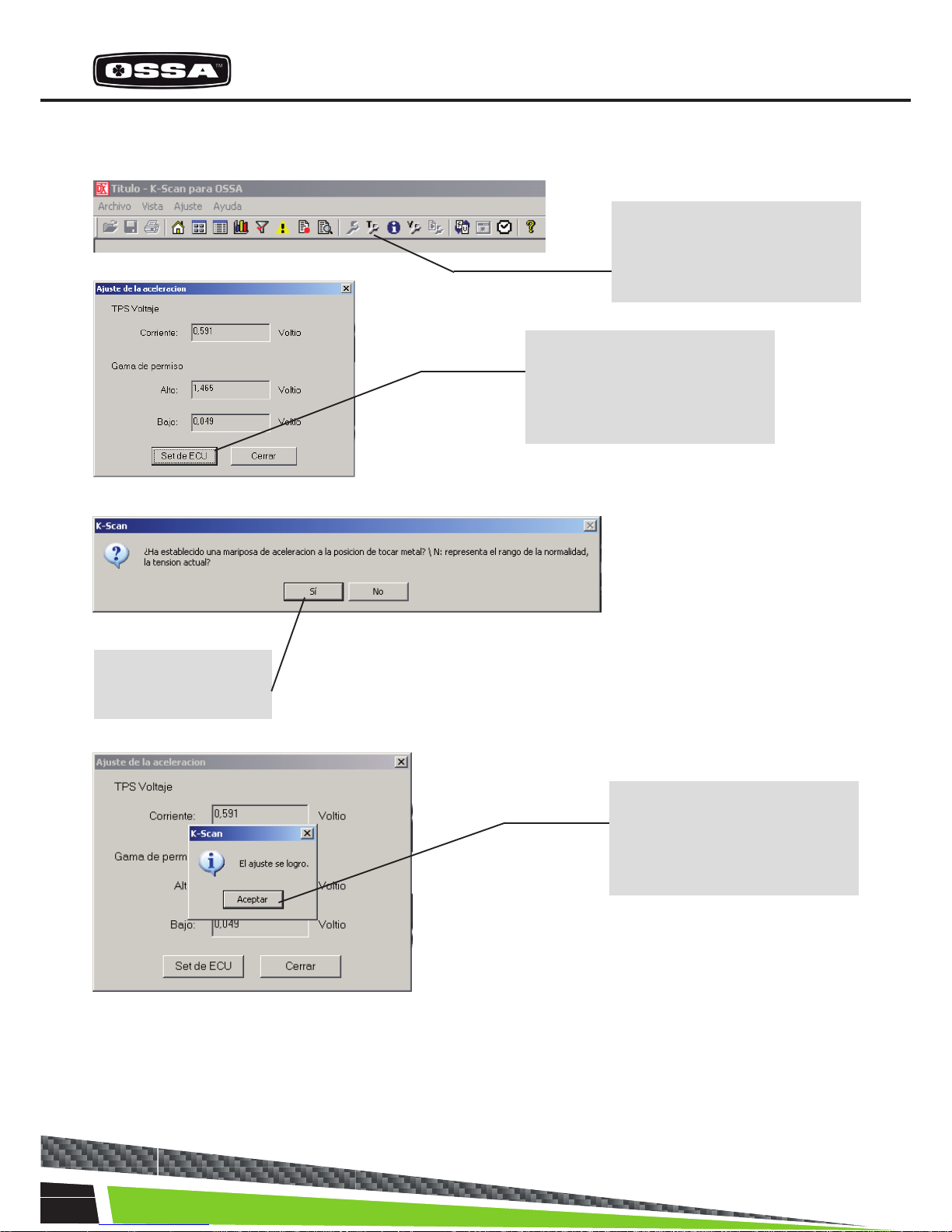
Step 1
Click the icon “Ajuste de la
aceleracion”
5. Adjustment of Idle Position: Execute the [Kscan] software.
6. IMPORTANT!!! In order to ensure correct updating of the ECU, please restart the Battery voltage
before starting the engine. If not updates will not be saved.
Step 2
With the thottle on the base
position (idle
position) click “Set de ECU”
Step 3
Click “Yes” to conrm.
Step 4
The adjustment ot the idle
position is done.
Click “Ok”.
Page 59

59
KWRITE PRO
Page 60

60
MAINTENANCE
5.1 CYLINDER HEAD
5.2 CYLINDER
Check the atness of the surface and the state of the rubber O-rings. If the O-rings are deteriorated
they should be replaced
Check the state of the ‘Nikasil’ plating. There should be no abnormal vertical scratches.
5.3 PISTON AND RINGS
5.4 PISTON ROD
Check the wear using a 0.25mm gauge for the maximum separation space on the rings.
If the space is larger, replace the rings.
Check if there is play on the rod. Without taking out the crankshaft from the crankcase, tapping it by
hand in a perpendicular direction to the axle of the rod.
5.5 CRANKSHAFT
5.6 CLUTCH
Check if it is centered and the possible wear on the are where the seals sit.
Check the atness of the clutch discs, and the total thickness of the pack (3+2 discs). The minimum
thickness is 9’75mm
Page 61

61
5.7 GEAR ASSEMBLY
5.8 TRANSMISSION
Check the state of the shift drum and the possible wear on the gear forks. The minimum thickness on
the contact part with the moving gears is 2’55mm
Replace sprockets and chain if the chain has 4 mm of play between the sprocket teeth.
5.9 BEARINGS
5.10 SEALS
Check their lateral play and smooth rolling.
Check the state of the seal lips, to make sure the wear has not made them at.
5.11 SPARK PLUG
5.12 ENGINE OIL
Ensure it is tightened to the recommended torque (see page 18)
Use 350 cm3 of Gear Extreme 75w oil. Change after rst ride and every 30 hours of use.
 Loading...