

Page 1
www.sylvania.com
The purpose of this document is to
demonstrate the LEDstixx Strip components
used to form a complete system. When
installed as instructed, this complete system
complies as a UL2108 Listed system.
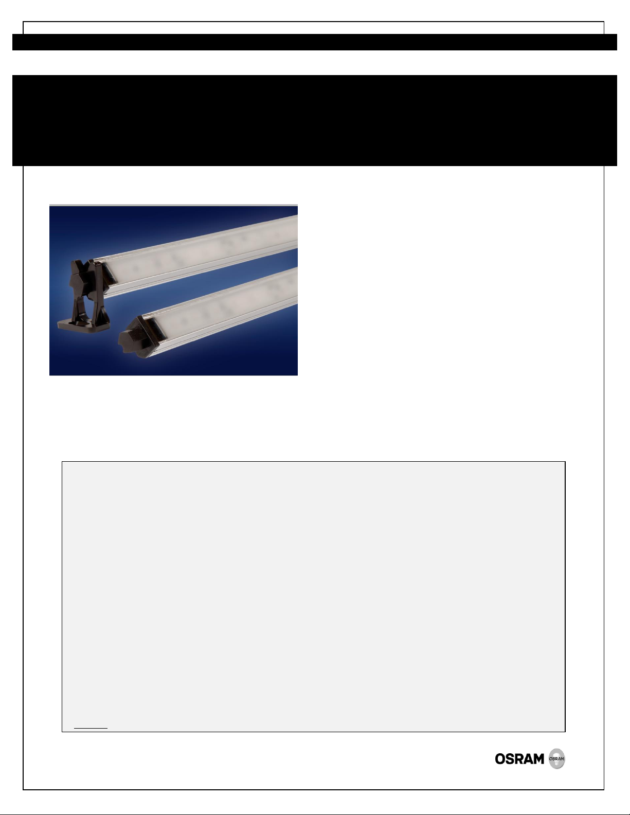
LED234
LEDstixx® Strip
Linear LED Lighting System
INSTALLATION GUIDE
WARNING: ONLY QUALIFIED PERSONNEL SHOULD PERFORM INSTALLATION
TO AVOID ELECTRICAL SHOCK OR COMPONENT DAMAGE, DISCONNECT POWER BEFORE ATTEMPTING INSTALLATION
OF THE POWER SUPPLIES AND/OR MODULES.
Failure to install the power supplies and/or LED modules in accordance with the National Electric Code (NEC), all applicable Federal,
State and local electric codes as well as the specific Underwriters Laboratories (UL) safety standards for the installation, location and
application may cause serious personal injury, death, property damage and/or product malfunction.
These instructions are guidelines for installation of LED modules and power supplies. Installation requirements may vary depending
on the application. Licensed electricians should provide all installation services for connection for both primary and secondary
(input/output) of the power supplies.
Identification and Warnings of Safety Hazards
In accordance with ANSI Z535.4-2002 the following system of identifying the severity of the hazards associated with the products is
used:
“DANGER”: Imminently hazardous situation which, if not avoided, will result in death or serious injury.
“WARNING”: Potentially hazardous situation which, if not avoided, could result in death or serious injury.
“CAUTION”: Potentially hazardous situation which, if not avoided, may result in minor or moderate injury or property damage. Also
used to alert against unsafe practices.
IGNORING A HAZARD WILL VOID ANY WARRANTY
Caution: Product is designed for Dry Location only installations.
Page 2
1.0 MECHANICAL INSTRUCTIONS
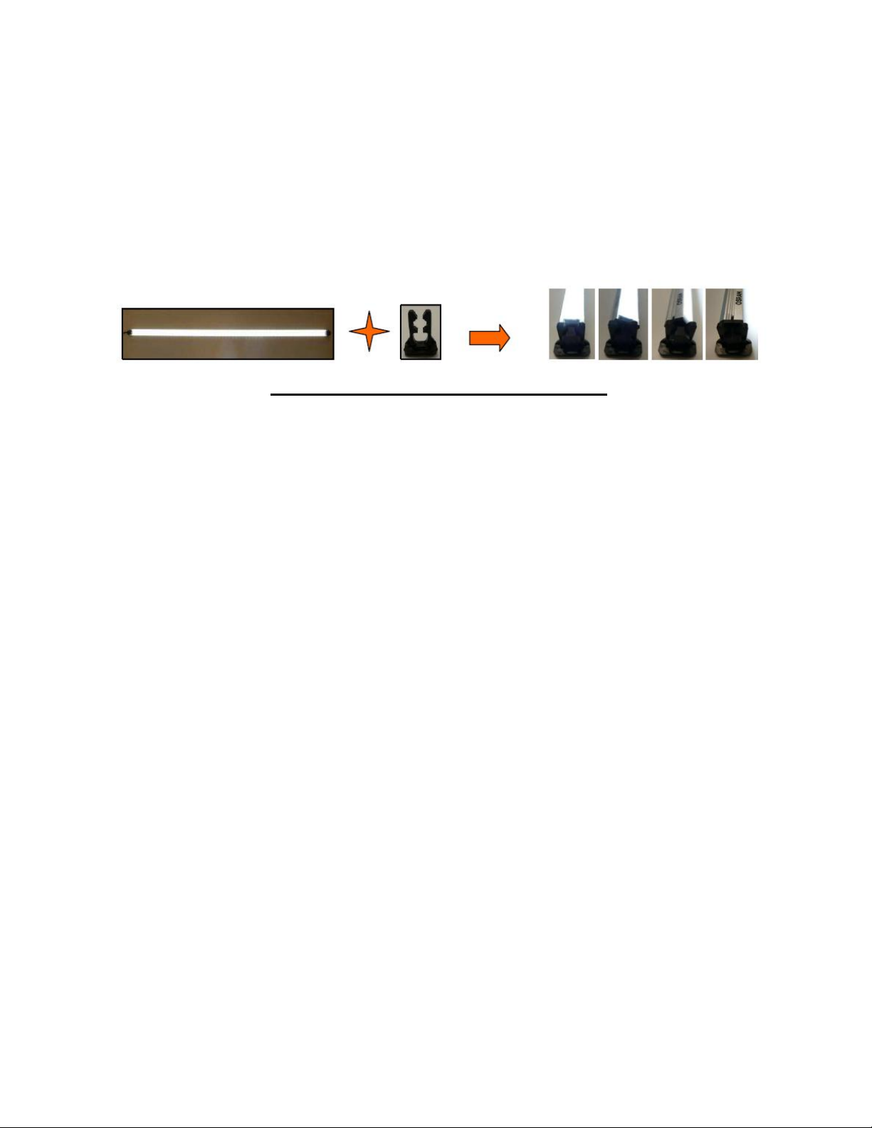
1.1 Sample Bill of Materials:
24 VDC, Class 2, UL Listed power supply
LEDstixx Strip LED linear lighting system available in 3 and 4 feet configurations, in
3000K and 4000K CCT. See Product Information Bulletin (PIBxxx) for part numbers,
descriptions, and specifications.
Mounting Clip Assembly, comes in quantities of 2 clips with screws per LEDstixx
Strip.
FIGURE 1: System Components Pictorial Diagram
1.2 Tools Required:
Phillips and/or flat blade screwdrivers
Needle nose pliers
Wire cutters/strippers
Tape measure
Eye protection
1.3 LED Assembly Installation:
1.3.1 The units come with mounting clips and screws for easy installation.
1.3.2 The mounting clip accommodates 180° angular rotation feature for aiming.
Caution: The engagement strength of the mounting clip is designed to handle the weight of the
product when the product is installed in a permanently located case. It is not designed to handle
potential forces from shock and vibration to which the product might be subjected during transit
should it be pre-installed inside a case. During transit of an assembled case, the LED assembly
must be removed from the mounting clip, packaged, and shipped separately from the case.
.
2
Page 3

2.0 ELECTRICAL INSTRUCTIONS
2.1 General Instructions:
For a UL2108 Code compliant installation, the LEDstixx® Strip must be installed with an
appropriate 24VDC, UL Listed, Class 2 power supply. For a list of UL Listed OPTOTRONIC®
power supplies reference Section 2.2.
Pay attention to standard Electrostatic Discharge (ESD) precautions when installing the
system.
2.2 Power Supplies:
The maximum total length of LEDstixx Strip product that can be operated on some example
power supplies is shown below:
Item Power Supply Ordering Description Maximum total lineal feet per power supply
51514 OT75W/24V/UNV 25
51626 OT96W/24V/UNV/JBX 32ft
51598 OT50W/24V/120V/LP 17ft
51627 OT240W/3x24V/120-240V/JBX 25ft/channel
51622 OT17/120-277/24E 6ft
Note:
1. Ensure power supply has adequate power to operate the load.
2. Observe correct electrical polarity. Incorrect polarity may destroy the module.
3. To accurately determine maximum LED load, the de–rating criteria listed in Application
Note “Determine the Maximum LED Load on the Constant Voltage Power Supplies” (#
LED026) must be factored in.
4. To determine remote wiring distances, reference the Application Note “Remote Wiring
Distances for LED Power Supplies” (# LED126).
3
Page 4

2.3 LEDstixx Strip Lighting System Wiring Diagram:
FIGURE 3: Wiring Diagram
3.0 PRODUCT RELATED INFORMATION:
3.1 List of Applicable and Related Documents:
Document #LED233- LEDstixx Strip Product Information Bulletin
Document # ECS050R12 - OPTOTRONIC® Electronic 24V DC LED Power Supplies
Document # ECS133 - OT96 Installation Guide
Document # ECS128 - OT240 Installation Guide
Document # LED026 - Determine the Maximum LED Load on the Constant Voltage Power
Supply
Document # LED126 -Remote Wiring Distances for LED Power Supplies
Document # LED157 - LEDstixx Lighting System Warranty
3.2 Responsibilities and Considerations:
3.2.1 Owner/User Responsibilities:
It is the responsibility of the contractor, installer, purchaser, owner, and user to
install, maintain, and operate the LEDstixx® Strip Lighting System in such a manner
as to comply with all state and local laws, ordinances, regulations, and the
American National Standards Institute Safety Code.
3.2.2 Installation Configurations:
When planning a LEDstixx Strip Lighting System installation, SYLVANIA suggests
doing the following:
Consult an Electrical Inspector to approve all wiring plans.
Refer to local and state codes for installation compliance.
Consult SYLVANIA Customer Service Center (1-800-LIGHTBULB).
.
OSRAM is a registered trademark of OSRAM GmBH
Specifications subject to change without notice
© 2012 OSRAM SYLVANIA Inc.
4
 Loading...