

Page 1
www.sylvania.com
This installation guide outlines step-by-step instructions
for proper mechanical and electrical installation of the
OSRAM LEDstixx® for Horizontal Refrigeration products
and power supplies. This document should never be
considered a substitute for any provision of a regulation
or state and/or legal code.
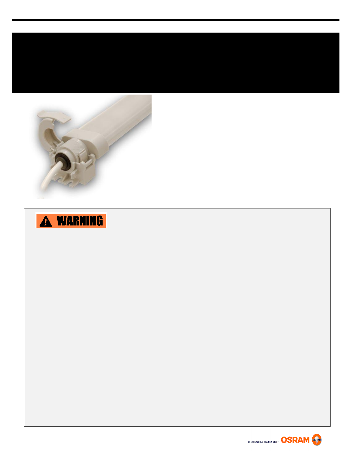
LED314
LEDstixx
®
for Horizontal Refrigeration
Lighting System for CANOPY Applications
ONLY QUALIFIED PERSONNEL SHOULD PERFORM INSTALLATION
TO AVOID ELECTRICAL SHOCK OR COMPONENT DAMAGE, DISCONNECT POWER BEFORE ATTEMPTING INSTALLATION
OF THE POWER SUPPLIES AND/OR MODULES.
Failure to install the power supplies and/or LED modules in accordance with the National Electric Code (NEC), all applicable Federal,
State and local electric codes as well as the specific Underwriters Laboratories (UL) safety standards for the installation, location and
application may cause serious personal injury, death, property damage and/or product malfunction.
These instructions are guidelines for installation of LED fixtures and power supplies. Installation requirements may vary depending on
the application. Licensed electricians should provide all installation services for connection for both primary and secondary
(input/output) of the power supplies.
“WARNING”: Risk of fire or electric shock. Luminaires, wiring, ballasts, or other electrical parts may be damaged when drilling for
installation of reflector kit hardware. Check for enclosed wiring and components.
“WARNING”: Risk of fire or electric shock. Reflector/retrofit kit installation requires knowledge of fluorescent lighting luminaires
electrical systems. If not qualified, do not attempt installation. Contact a qualified electrician.
“WARNING”: Risk of fire or electric shock. Install this kit only in luminaires that have the construction features and dimensions shown
in the “product diagram”.
“WARNING”: To prevent wiring damage or abrasion, do not expose wiring to edges of sheet metal or other sharp objects.
Identification and Warnings of Safety Hazards In accordance with ANSI Z535.4-2002 the following system of identifying the
severity of the hazards associated with the products is used:
“DANGER”: Imminently hazardous situation which, if not avoided, will result in death or serious injury.
“WARNING”: Potentially hazardous situation which, if not avoided, could result in death or serious injury.
“CAUTION”: Potentially hazardous situation which, if not avoided, may result in minor or moderate injury or property damage.
Also used to alert against unsafe practices.
IGNORING A HAZARD WILL VOID WARRANTY
Page 2
Philips and/or Flat Blade
Screwdrivers
Needle Nose Pliers
Wire Cutters/Strippers
Hex Keys
Tape Measure
Eye Protection
Work Gloves
Nominal Case Length
3-foot
4-foot
8-foot
12-foot
Case Canopy Lighting Fixture Wattage
13.0W
19.0W
38.0W
57.0W
Case Canopy Lighting System Wattage*
15.3W
22.4W
44.7W
67.1W
*Approximate system wattage including power supply losses. Assumes 85% efficient power
supply is used. A maximum of 12 feet of LEDstixx Canopy fixtures can be connected in series.
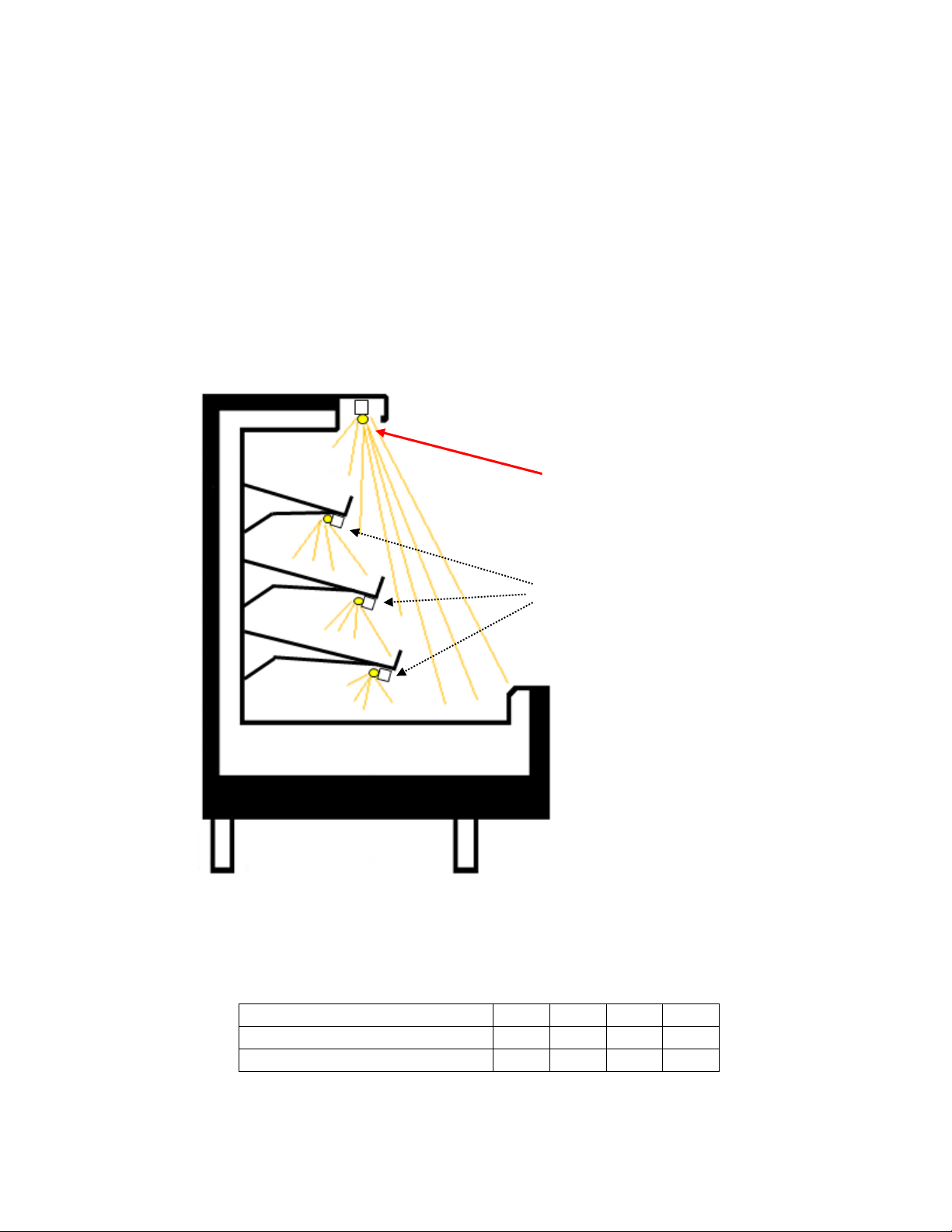
Refrigerated Case Canopy Lighting
Approximate System Wattages
Refrigerated Case Under-Shelf Lighting
1.0 MECHANICAL INSTALLATION INSTRUCTIONS
1.1 Tools Required:
1.2 Example Case Configuration:
1.3 LEDstixx Refrigeration Canopy Lighting Wattages
Page 3
1.4 Case Identification
Note: there are two mechanical methods of attaching the LEDstixx Canopy fixture
to the refrigerated case. Installer may either screw the supplied Mounting Brackets
to the existing case body OR use optionally available Tombstone Adaptors that
mount directly to existing fluorescent tombstone sockets, if available. Existing
tombstone sockets are only used for mechanical mounting and not for making any
electrical connection. If not using the optional Tombstone Adaptors, skip to section
1.5.3.
Tombstone Adaptors
Figure B
Mounting Brackets
If the installation is a replacement of an existing fluorescent system, it is recommended that the
case manufacturer be identified. Case brand labels are generally displayed near the top of the
case, at the frame header and should identify the manufacturer. Obtaining this information may
be beneficial as many case manufacturers offer specific installation, repair and replacement
documents online. This installation guide is written such that any removal or access instructions
are dictated by the manufacturer’s provisions and to instruct the installer concerning any product
specific instructions once access and provision are made.
WARNING – Turn off and disconnect the power to the case and the
ballast before proceeding with the installation.
1.5 LEDstixx Horizontal Refrigeration Canopy Fixture Installation Instructions
1.5.1 If not using the Tombstone Adaptors, start at section 1.5.3. If using the optional
Tombstone Adaptors, snap the Tombstone Adaptors on to the press fit clips on outer
ends of the Mounting Brackets as shown in Figure B.
1.5.2 Snap the Tombstone Adaptors on to the existing fluorescent tombstone sockets as
shown in Figures C and E and skip to section 1.5.6.
Page 4

Figure C
Existing
Tombstone
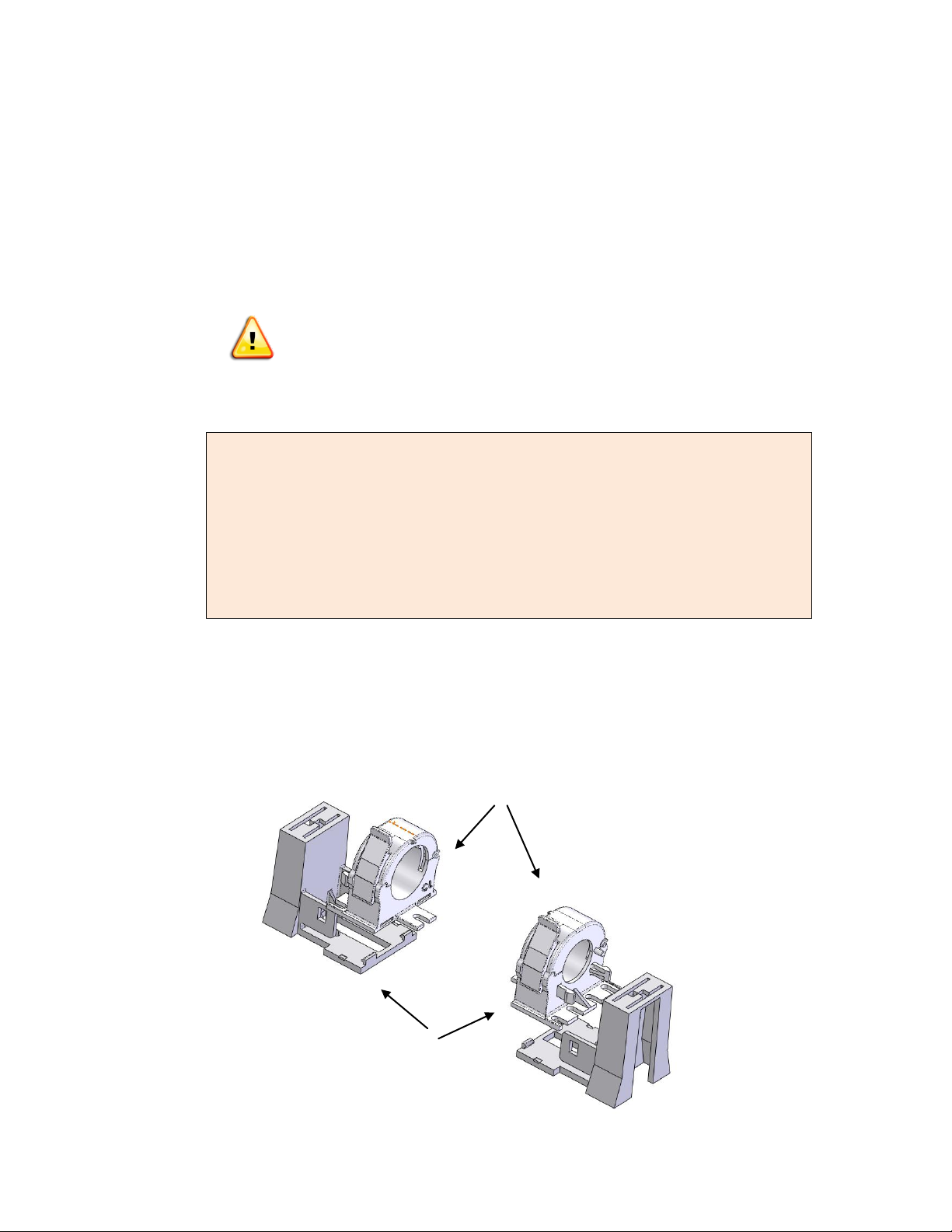
1.5.3 The fixture includes two Mounting Brackets (Figure B), one per each end.
Attach one to each end of the fixture with the screw slots facing outwards.
Be sure they are attached such that the screw slots face outwards and such
that the side of the Mounting Bracket with larger inside diameter opening
faces the LEDstixx fixture body. The release clip on the Mounting Bracket
allows for opening up the bracket to install the fixture body and for
rotational aiming of the fixture body after it is installed.
1.5.4 Mark mounting hole locations.
1.5.5 Secure each Mounting Bracket to the horizontal surface of the refrigerated
case using two self tapping 3mm screws in each bracket.
1.5.6 Install the LEDstixx Canopy fixture body into the Mounting Brackets such that
the arrows on the back of the ends of the fixture body point into the case
when mounted up against the underside of the canopy. The angled reflector
surface of the fixture should face into the refrigerated case. See Figures D
and F.
1.5.7 Close the release clip on the left side Mounting Bracket.
1.5.8 Rotate LEDstixx Canopy fixture body for aiming.
1.5.9 Close the release clip on the right side Mounting Bracket to lock fixture in
place. The Release Clip and be opened later for future aiming once units are
energized.
1.5.10 The LEDstixx Canopy fixture is rotatable in 2.5° increments. If the fixture
body needs to be aimed, open the right side release clip, rotate the fixture
body, and snap the release clip closed to secure the fixture in the desired
position.
Page 5

Figure E – Showing use of Mounting Bracket and optional Tombstone Adaptor
Figure F – Showing use of Mounting Bracket WITHOUT use of optional Tombstone Adaptor
Figure G- Use the Figure G template to drill for M3 Sheet Metal Screws and secure holders to fixture before
\
Page 6

2.0 ELECTRICAL INSTRUCTIONS
2.1 General Instructions:
If additional wiring becomes necessary, it is the responsibility of the installer to provide this wiring
and ensure that the wiring meets all applicable Class 2 requirements as pertains to the installation.
Pay attention to standard Electrostatic Discharge (ESD) precautions when installing the system.
2.1 Wiring Instructions and Power Supply Installation Instructions
2.1.1 When retrofitting an existing refrigerated case, access the existing
fluorescent ballast.
2.1.2 Disconnect the line and load side connectors from the ballast. Unscrew the
ballast mounting screws and remove the ballast.
2.1.3 Install the new Optotronic OT75 power supply and re-use the previous
ballast’s screws to secure the OT75 into the existing mounting holes.
2.1.4 The LEDstixx Canopy fixtures can be wired in parallel to the power supply or
connected in daisy chain series. Up to 12 feet of the LEDstixx Canopy fixtures
can be daisy chained together in series. See wiring diagrams in Figure G and
Figure H for wiring options.
2.1.5 Connect 24V output leads from power supply to existing wiring used
previously for the removed fluorescent system making connections for
multiple fixtures as shown in Figures G or Figure H.
Note:
Depending on the size of the ballast removed, it may become necessary to drill an
additional mounting hole to match the foot print of the LED Power supply. The AC
ground wire from the line side wiring must be firmly bonded to the case of the LED
power supply.
2.2 Wiring Diagrams
3.0 Figure G – Basic Wiring Diagram Showing Parallel Connection
Page 7

Figure H – Basic Wiring Diagram Showing Series Connection
LED 314 07/13
OSRAM is a registered trademark of OSRAM GmBH
Specifications subject to change without notice
© 2013 OSRAM SYLVANIA Inc. 1/13
Notes:
1. The wiring diagram is purely diagrammatic. The power supply DC output wiring must be
kept separate from any AC wiring. Therefore the orientation of the LEDstixx and
subsequent wiring schemes to maintain this separation must be determined in the field.
2. Contractor is responsible for providing any additional wiring necessary to feed from the
output of the power supply to the “Input Connector” noted in the diagram. Contractor is
responsible for the connection of said “Input Connector” to additional wiring.
4.0 CLEANING and CARE
To avoid product damage do not use chemical solutions to clean the lens
Keep the outside clean. Wipe with gentle liquid dish detergent. Dry with a soft cloth
Do not wipe the lens with a wet towel. This could leave a residue that can cause damage
The lens and the housing need to be cleaned from time to time with a gentle liquid detergent
Do not use scouring pads, bleach or cleaners containing bleach because this can scrape and
harm the finish
5.0 RELATED INFORMATION
5.1 List of Applicable and Related Documents:
Document LED313 – LEDstixx Product Information Bulletin (PIB)
Document LED315 – LEDstixx for Horizontal Refrigeration Under-Shelf Lighting
Installation Guide
Document ECS050 – Power Supply Product Information Bulletin (PIB)
Document LED093 – Electrostatic Discharge Protection for LED Systems
Document LED157 - LEDstixx® Lighting System Warranty
5.2 Responsibilities and Considerations
5.2.1 Owner/User Responsibilities:
It is the responsibility of the contractor, installer, purchaser, owner, and user to
install, maintain, and operate LEDstixx and components in such a manner as to
comply with all state and local laws, ordinances, regulation, and the American
National Standards Institutes Safety Code.
5.2.2 Installation Configurations:
When planning a LEDstixx installation, OSRAM SYLVANIA suggests the following:
Consult and Electrical Inspector to approve all wiring plans.
Refer to local and state codes for installation compliance.
Consult OSRAM SYLVANIA Customer Service Center @ 1-800-LIGHTBULB
 Loading...