

Page 1
SYLVANIA LED 2x2 RETROFIT KIT INSTALLATION INSTRUCTIONS
INSTALLATION SAFETY INFORMATION
The SYLVANIA LED 2x2 Retrofit Kit uses self-drilling hardware for ground straps and power supply installation. Check for electrical wiring and
components above luminaire housing prior to installation to avoid damage to A/C, sprinkler or other electrical systems.
WARNING—Risk of fire or electric shock. Luminaires wiring, ballasts, or other electrical parts may be damaged when drilling for installation of
reflector kit hardware. Check for enclosed wiring and components.
WARNING—Risk of fire or electric shock. LED Retrofit Kit installation requires knowledge of fluorescent lighting luminaires electrical systems. If
not qualified, do not attempt installation. Contact a qualified electrician.
WARNING—Risk of fire or electric shock. Install this kit only in the luminaires that has the construction features and dimensions shown in the
enclosed photographs and/or drawings.
WARNING—To prevent wiring damage or abrasion, do not expose wiring to edges of sheet metal or other sharp objects.
WARNING—Do not make or alter any open holes in an enclosure of wiring or electrical components during kit installation.
INSTALLATION OF THIS LED RETROFIT KIT ASSEMBLY REQUIRES A PERSON FAMILIAR WITH THE CONSTRUCTION AND OPERATION OF LOW
VOLTAGE LUMINAIRE ELECTRICAL SYSTEMS AND THE HAZARD INVOLVED.
Contact your local OSRAM SYLVANIA representative for any assistance needed with this installation.
LED262 1/2012
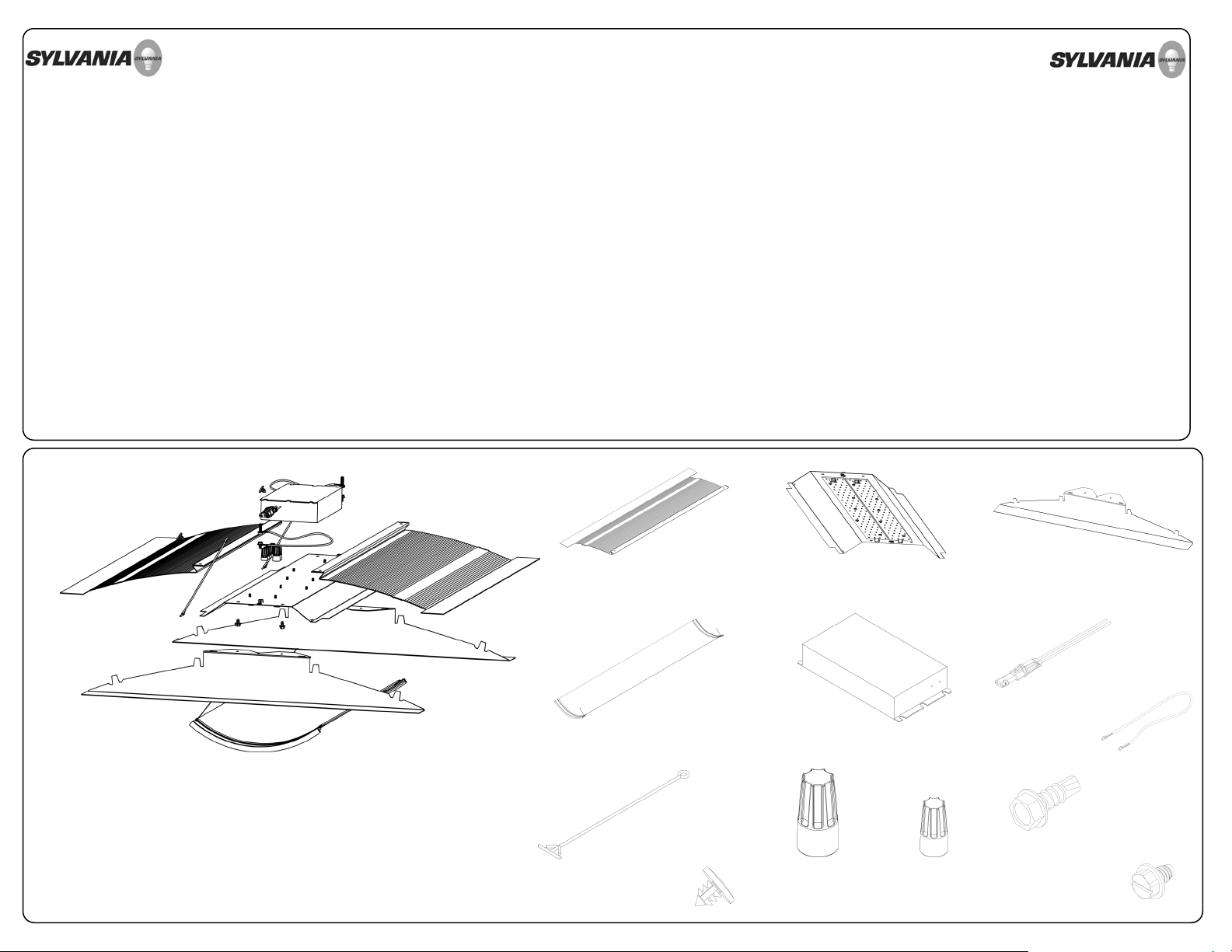
LED RETROFIT KIT EXPLODED VIEW
REFLECTOR BRACKET
QUANTITY: 2
LIGHT ENGINE PANEL
QUANTITY: 1
DIFFUSER LENS ASSEMBLY
QUANTITY: 1
SYLVANIA LED DRIVER
QUANTITY: 4
LED SUB ASSEMBLY
SAFETY TETHER
QUANTITY: 2
PUSH FASTENER
QUANTITY: 2
ORANGE WIRE NUT
QUANTITY: 2
BLUE WIRE NUT
QUANTITY: 5
END BRACKET
QUANTITY: 2
DRIVER QUICK
DISCONNECT
12” 18 GA GREEN
GOUND STRAP
QUANTITY: 2
#8-32 1/2”
HEX HEAD
SELF DRILLING SCREW
QUANTITY: 3
#8-32 3/8”
SLOTTED HEX HEAD
SELF THREADING SCREW
QUANTITY: 7
QUANTITY: 1
Page 2

PREPARE EXISTING FIXTURE FOR INSTALLATION
1
REMOVE EXISTING:
LENS / LENS FRAME
PARABOLIC LOUVER
REFLECTORS / BALLAST COVERS
BRACKETS
LAMPS / LAMP HOLDERS
Prior to installation, remove all electrical parts and the
ballast compartment cover leaving only the supply and
grounding leads.
INSTALL LED DRIVER AND DRIVER DISCONNECT
2 3
2X
DANGER—RISK OF SHOCK—DISCONNECT POWER BEFORE
INSTALLATION.
Using the provided self-drilling screws, properly affix specified
LED Driver to fixture. When drilling for installation of retrofit kit
hardware, please check for enclosed wiring and
components. Properly install Driver Disconnect to driver; black
to black and white to white.
NOTE: LED driver location will depend on troffer depth. The LED
driver may need to be off centered when installing in a
shallow troffer.
INSTALL REFLECTOR BRACKETS INTO EXISTING FIXTURE
2X
The LED Retrofit Kit is designed to rest between the existing
fixture body and the T-grid. Remove protective coating from
brackets before installing. Lift one side of the existing fixture
and place Reflector Bracket between the existing Fixture
body and T-grid . Lower the fixture body onto the Reflector
Bracket. Repeat procedure to install the second Reflector
Bracket.
INSTALL GROUND STRAPS & END BRACKETS
4 5
2X
2X
2X
+
Remove PVC film from End Brackets before installing. Use
3/8” slotted screws to secure one end of the green ground
strap to the small hole found on End Bracket. Lift one end
of the existing fixture and place End Bracket between the Tgrid and the existing Fixture body. Position the Reflector
Bracket so that the slots on the Reflector Bracket mate with
the tabs on the End Brackets. Repeat the procedure for the
second End Bracket. DO NOT bend the tabs yet.
Bond the retrofit assembly to the existing fixture by
connecting a Green Ground Strap directly to mains ground.
BEND TABS TO SECURE ASSEMBLY GROUND & SECURE RETROFIT KIT INTO EXISTING FIXTURE
6
+
With both Reflector Brackets and both End Brackets installed
and correctly positioned, secure the assembly by folding over
the two inner locking tabs applying finger pressure. The
remaining outer tabs are for alignment only. There should be
Four tabs in total that are folded over.
Page 3

ASSEMBLE SAFETY TETHERS TO LIGHT ENGINE PANEL
7
+
ASSEMBLE LIGHT ENGINE PANEL TO FIXUTRE
8
WIRE LIGHT ENGINE PANEL TO LED DRIVER
9
2X
Locate the rectangular slots on the edge of the Light Engine
Panel. Insert the circular end of the Light Engine Panel Safety
Tethers into the slots and pull until the barbs fasten. Verify
that the tethers are locked into place.
INSTALL LIGHT ENGINE PANEL TO FIXTURE
10
+
4X
Install the Light Engine Panel to the fixture buy setting the end
flanges into the ‘Z’ shaped recesses in the Reflector Brackets.
The Light Engine Panel should positively snap into place.
Secure the Light Engine Panel to the fixture by using the
provided self drilling screws.
2X
To assemble the Light Engine Panel to the fixture, locate
the rectangular slots on the End Brackets. Insert the
circular end of the Light Engine Panel Safety Tether into the
rectangular slots. Using the black plastic Push Fastener,
lock the circular end of the Light Engine Panel Safety
Tether into the End Bracket. Repeat the steps for the
second Light Engine Panel Safety Tether.
INSTALL DIFFUSER LENS ASSEMBLY
11
A
A Prior to installing the Diffuser Lens Assembly, pinch the ends
of the nylon tethers so that the fastening ends form a barb.
Refer to corresponding image A.
B With the nylon tethers ready to install, locate the two slots on
the Reflector Brackets where the nylon tethers will insert. Push
the end of the nylon tether into the slot and check that the
tethers secure into the Reflector Brackets. This is shown in B.
C With the nylon tethers secure into the Reflector Bracket,
insert one edge of the lens assembly into the lens groove in
the Reflector Bracket. Refer to image C for lens groove
location.
5X
2X
Using the provided Wire nuts, correctly wire the driver leads
to the LED input connector harnesses.
NOTE: Above image and all images with wires are for
illustration purposes only. Please follow driver wiring
instructions.
B
D When the first edge of the lens assembly is properly seated
into the lens groove, place the second edge of the lens
assembly into the other Reflector Bracket’s lens groove. The
lens groove locations are visible in image D. The gasket will
expand to fit the lens groove. Outward pressure from the
lens and friction from the gasket expanding will serve to
secure the lens assembly into the retrofit kit.
E Image E shows the finished assembly of the retrofit kit.
C
D E
 Loading...