

Page 1
www.sylvania.com/LED
LED297
Chain X2 LED Lighting System
INSTALLATION GUIDE
WARNING: ONLY QUALIFIED PERSONNEL SHOULD PERFORM INSTALLATION
TO AVOID ELECTRICAL SHOCK OR COMPONENT DAMAGE, DISCONNECT POWER BEFORE PERFORMING INSTALLATION OF THE POWER
SUPPLIES, MODULES, AND/OR RGB CONTROLLERS.
Failure to install the power supplies and/or LED modules in accordance with the National Electric Code (NEC), all applicable Federal, State, and local
electric codes as well as the specific Underwriters Laboratories (UL) safety standards for the installation, location and application may cause serious
personal injury, death, property damage and/or product malfunction.
These instructions are guidelines for installation of LED modules and power supplies. Installation requirements may vary depending on the application.
Licensed electricians should provide all installation services for connection for both primary and secondary (input/output) of the power supplies.
Note: For sign retrofits, Chain X2 modules and associated 12V power supplies must only be installed in UL Listed Signs.
1.0 Prepare for Installation
1.1 Tools Required:
- Wire stripper/cutter
- Screwdriver
- Measuring tape
1.2 Supplies Required:
- PLTC Cable
- Wire nuts
- #8 hex/pan head type screws or rivets
1.3 Carefully remove existing neon or fluorescent tubes, HID or incandescent light sources and power
supplies and/or ballasts if necessary.
1.3.1 Make sure power is turned off.
1.3.2 Remove all existing screws, sockets and wiring.
1.3.3 Dispose of all old sign components in the proper manner.
1.3.4 Clean the inside of the sign ensuring it is free of dirt.
2.0 Mechanical Installation
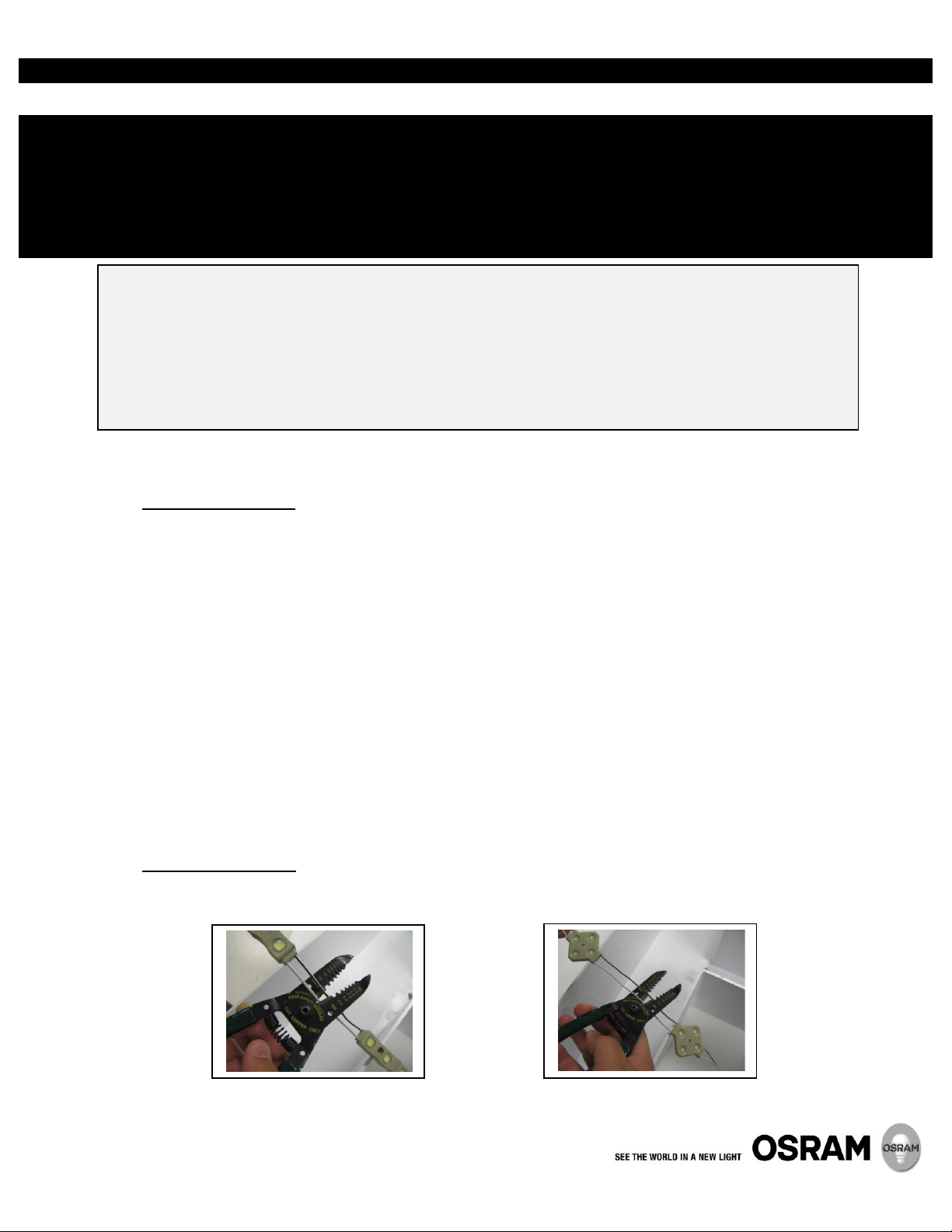
2.1 Measure the appropriate amount of product for the length of the application and cut. Cuts can be made
between any two modules.
Page 2
2
2.2 Peel plastic tape backing to expose double sided tape and place modules in desired
location.
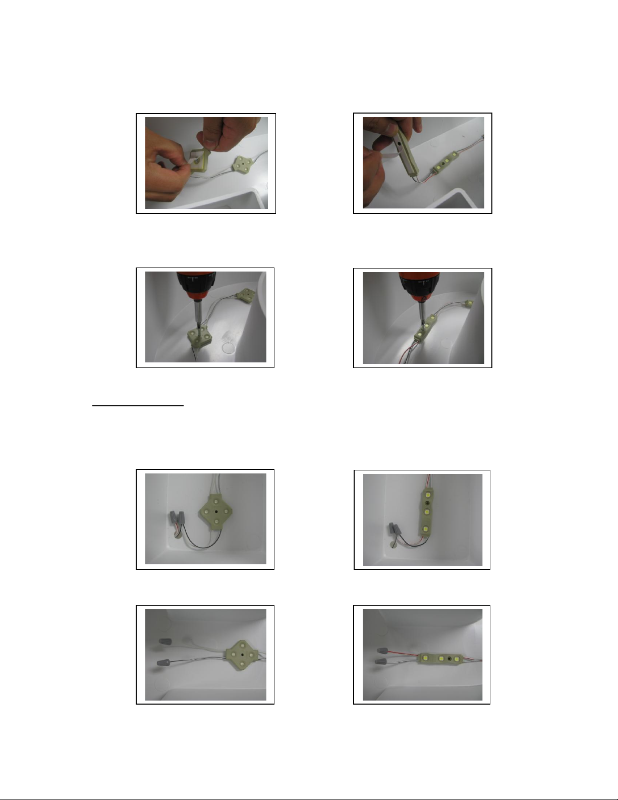
2.3 Secure the modules through the mounting hole using screws or rivets.
Do not overtighten.
3.0 Electrical Installation
3.1 Use wire nuts to connect the red striped (+) input wire of the modules to the red (+) output
wire of the 12V power supply.
Connect the black striped (-) input wire of the modules to the blk (-) output wire of the 12V
power supply.
3.2 Cap off any unused connection wires when finished.
Page 3

3
3.3 Power Supply Information:
Problem
Possible Cause
Corrective Action
Entire sign does not light
No input power
Check AC connection to power supply.
Entire sign/one or more LED
runs do not light
No power to LED modules
Check power supply connection to modules.
Check DC polarity- power supply red output wires must be connected
to red striped module wires, power supply blue output wires must be
connected to gray striped module wires.
Verify power supply output voltage is 12V +/- 1.0V
Part of an LED run does not light
No power to that run
Check module to module connection for correct polarity.
One module does not light
Module has been
damaged
Replace the module. Observe correct polarity.
Chain X2-L150
Cool White/ Warm White
Chain X2-L125
Red / Orange / Yellow
Chain X2-L200
Blue / Green
Item
Number
Ordering Abbreviation
Total Feet
per
Power Supply
Max Modules
per
Power Supply
Total Feet
per
Power Supply
Max Modules
per
Power Supply
Total Feet
per
Power Supply
Max Modules
per
Power Supply
51601
OT10/120-240/12E
6.5
13 8 16 5 10
51602
OT25/120-277/12E
16.5
33
20
40
12.5
25
51603
OT60/120-277/12E
40
80
48
96
30
60
51633
OT60W/12V/UNV/DIM
40
80
48
96
30
60
NAED
Ordering Description
Power Supply
Wattage
Input Voltage
(VAC)
Input Current
(A)
Output
Voltage (V)
Minimum Loading Chain
X2
51601
OT10/120-277/12E
10W
120/240
0.18/0.09
12 +/- 1.0
2 Modules
51602
OT25/120-277/12E
25W
120/277
0.26/0.12
12 +/- 1.0
2 Modules
51603
OT60/120-277/12E
60W
120/277
0.64/0.28
12 +/- 1.0
2 Modules
51633
OT60W/12V/UNV/DIM
60W
120/277
0.60/0.26
12 +/- 1.0
2 Modules
OSRAM and OPTOTRONIC are registered trademarks of OSRAM GmbH
Specifications subject to change without notice
© 2013 OSRAM SYLVANIA Inc. 3/2013
NOTE: Power supply spacing to other heat producing components shall be minimum 2 inches spacing to
sidewalls, and minumum 2 inches spacing to top of enclosure.
4.0 Troubleshooting Guide
 Loading...