

Page 1
TOUCH DIM LS/PD LI
Description
A B C
Function and application
The TOUCH DIM LS/PD LI sensor regulates the brightness
at the workplace and in ofce areas to increase the working
comfort and to save energy.
The sensor can be installed in luminaires (e.g. oor standing
luminaires) or in false ceilings.
Function
The sensor measures the brightness in the area to be regulated
and keeps this to an adjustable set value by introducing articial
light according to the amount of daylight available.
The sensor also detects the movements of people.
As daylight increases the articial light is reduced . The sensor
no longer detects any motions, it switches the luminaires off.
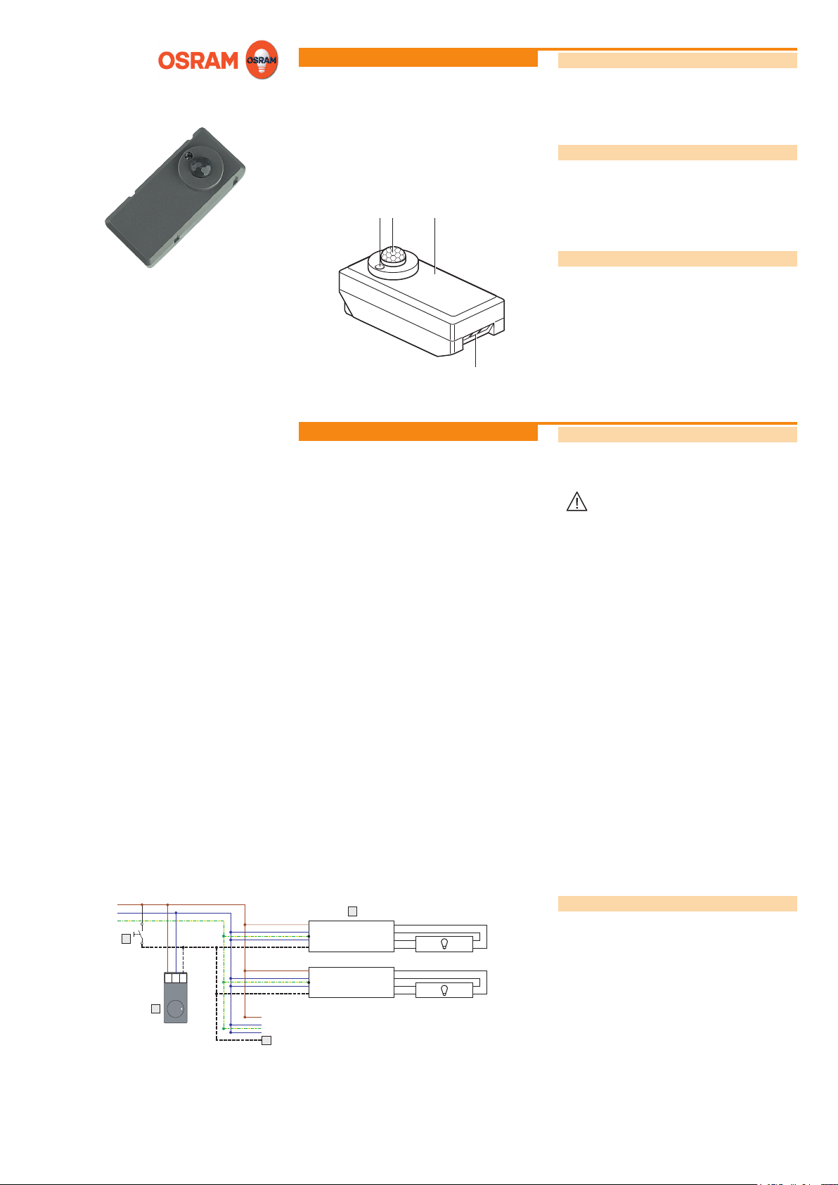
Construction
The sensor is made up of the following components:
• Light sensor (A)
• Motion sensor (B)
• Housing (C)
• Connections (D) for signal line, zero line and phase
Light and motion sensor
Fitting instructions
Installation
D
Safety instructions
The sensor must only be installed and put into operation by
a qualied electrician. The applicable safety regulations and
accident prevention regulations must be observed.
WARNING!
Exposed, live cables or damaged housing.
Danger of electric shock!
• Only work on the sensor when it is deenergized.
• Disconnect the sensor or luminaire from the
power supply if the housing or plastic lens is
damaged.
CAUTION!
Destruction of the sensor and other devices
through incorrect mounting!
• Only use electronic OSRAM ballast coils of the
type QUICKTRONIC INTELLIGENT DALI (QTi
DALI…DIM), HALOTRONIC INTELLIGENT
DALI (HTi DALI…DIM) or OPTOTRONIC
INTELLIGENT DALI (OT…DIM).
• Do not operate any other other control units on
the control line.
• Do not exceed the maximum number of
ballast coils and maximum overall cable length
between the operating button, sensor and
ballast coil.
• Do not connect control line with external
voltage.
• Only supply sensor with an AC operating voltage, especially in networks with UPS systems.
L
N
PE
E
N S
L
H
Touch DIM
Sensor
G
~
~
DA
DA
~
~
DA
DA
F
EVG QTi DALI
EVG QTi DALI
1
2
3
4
1
2
3
4
Connecting the sensor
E Operating pushbutton: Same phase as sensor.
F Electronic ballast coil (EVG): Connect max. 4 ballast coils.
G Signal line: Max. 10 m.
H Sensor: Cable connection via 3-wires permitted for mains
voltage. Do not switch the sensors in parallel.
Continued on the back page!
Page 2
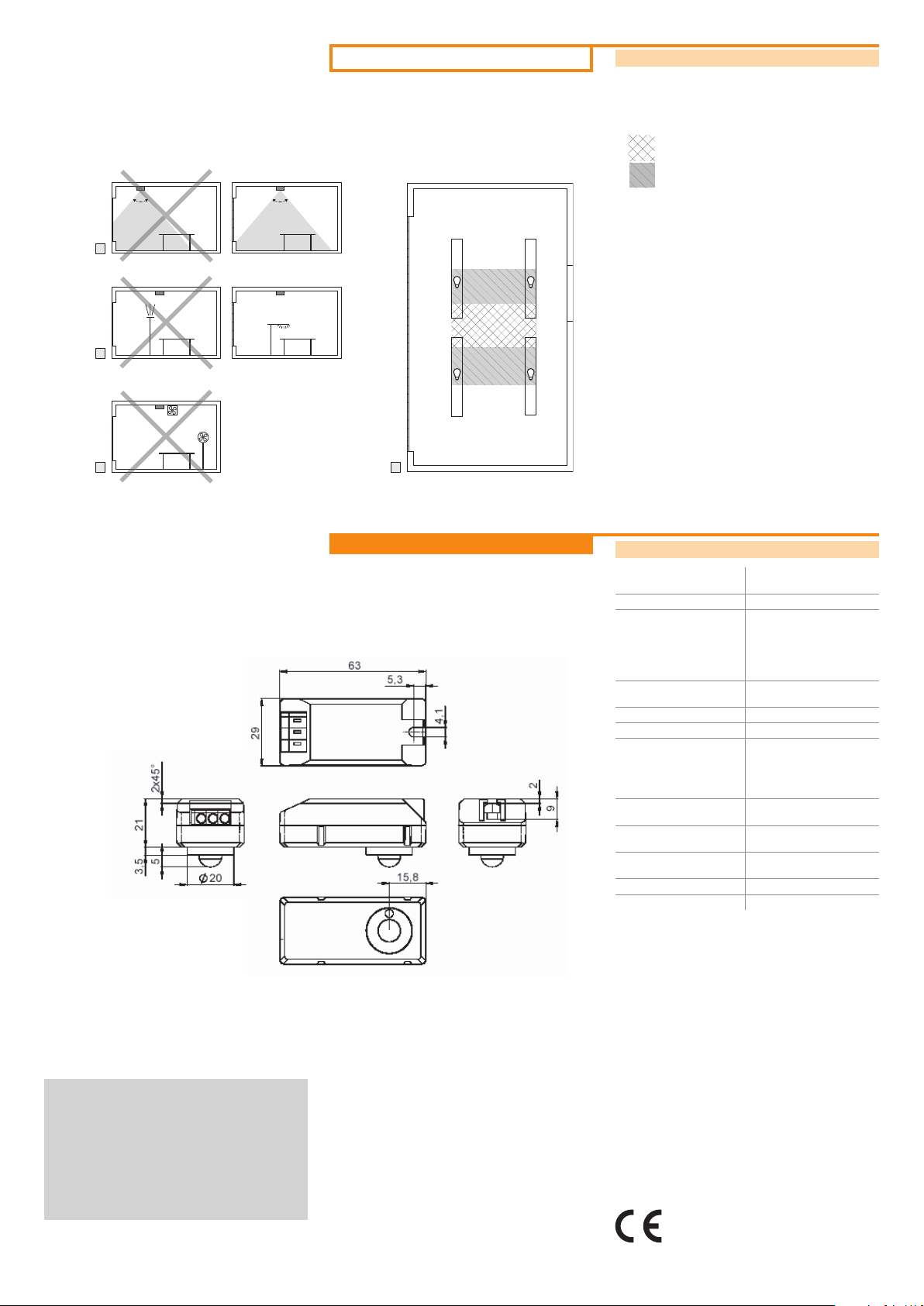
Fitting (cont.)
80° – 100°
Touch DIM Sensor
80° – 100°
Touch DIM Sensor
Selecting the installation location
I Surveillance cone: entire workplace; not on window surfaces
K Avoid direct light irradiation
L Avoid drafts (e.g. from ventilators or fans)
M Place centrally.
Optimum installation location
Possible installation location
80° – 100°
I
K
L M
80° – 100°
Appendix
Technical data
Operating voltage 220-240 V / 50-60 Hz (no DC
Connections L, N, S (signal)
Interface Osram-specic, maximum
Maximum overall length of
the signal line
Power consumption approx. 0.5 W
Operating temperature 0 °C ... +50 °C
Adjustable light value approx. 0-300 lx measured
operation)
4 QTi DALI coil ballast
or 4 HTi transformers or
4 OTi LED dimmers can be
connected
10 m
on the sensor (corresponds
to approx. 10-1200 lx on the
work surface)
VII 2008
TouchDIM-LSPD-LI_ma0807en_we1.02.indd
OSRAM GmbH
Kunden Service Center
Customer-Service-Center (CSC)
Steinerne Furt 62
86167 Augsburg
Germany
Tel : +49 (0) 1803 677 - 200
(kostenpichtig / charges apply)
Fax.: +49 (0) 1803 677 - 202
www.osram.com
www.osram.de
40083210230250
4008321023025
Motion detection area conical, approx. 80° ... 100°
Pollution severity 2 (dry, not conductive to
Dimensions 63 x 29 x 21 mm
Protection class II
Protection type IP 20
The EMC requirements to EN 61547 are fullled.
Conformity with the relevant EU directives is
conrmed by the CE symbol.
aperture angle
IEC 664)
(L x W x H)
 Loading...