

查询SPLMN81G2供应商
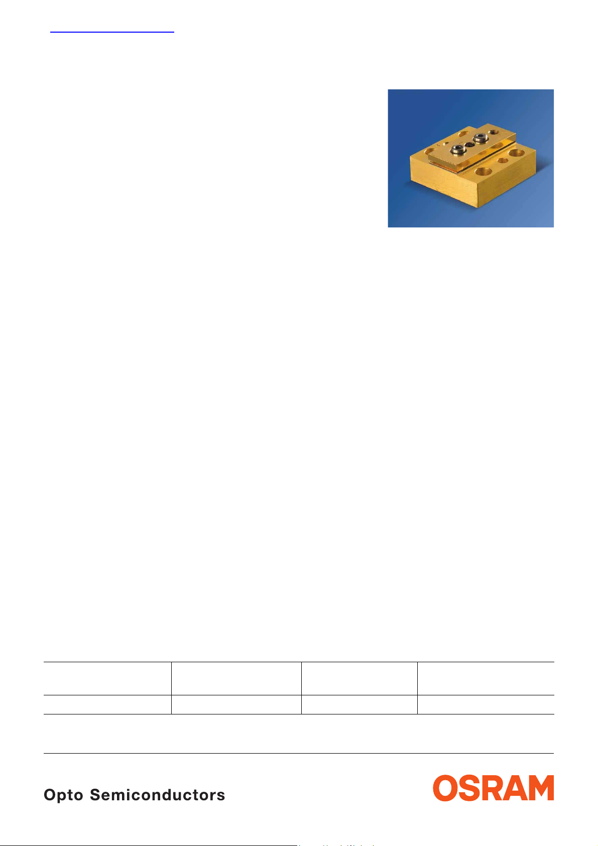
Passiv gekühlter Diodenlaser-Barren, 50 W cw bei 808 nm
Passively Cooled Diode Laser Bar, 50 W cw at 808 nm
SPL MN81G2
Vorläufiges Datenblatt / Preliminary Data Sheet
Besondere Merkmale
• Laserbarren auf passiv gekühlter
Wärmesenke, kein Kühlwasser erforderlich
• Für Dauerstrich- (CW) und
quasi-kontinuierlichen Betrieb (QCW)
• Zuverlässiges Halbleiter-Material mit
Mindest-Lebensdauer von 10.000 h,
typischerweise >50.000 h
• Geringer thermischer Widerstand
• Geringer smile (< 2,5 µm), geringe
mechanische Toleranzen
Anwendungen
• Pumpen von Festkörperlasern
• Direkte industielle Anwendungen (Löten,
Oberflächenbehandlung,...)
• Medizinische Anwendungen
• Druckanwendungen
Sicherheitshinweise
Je nach Betriebsart emittieren diese Bauteile
hochkonzentrierte, nicht sichtbare InfrarotStrahlung, die gefährlich für das menschliche
Auge sein kann. Produkte, die diese Bauteile
enthalten, müssen gemäß den Sicherheitsrichtlinien der IEC-Norm 60825-1 behandelt
werden
Features
• Laser bar mounted on passive mount, no water
required
• For continuous wave (cw) and quasi continuous
wave (qcw) operation
• Highly reliable semiconductor material with
minimum life time of 10,000 h,
typically >50,000 h
• Low thermal resistance
• Low smile (< 2.5 μm) and low mechanical
tolerances
Applications
• Pumping of solid state lasers
• Direct industrial applications (soldering, surface
treatment,…)
• Medical applications
• Printing applications
Safety Advices
Depending on the mode of operation, these
devices emit highly concentrated non visible
infrared light which can be hazardous to the
human eye. Products which incorporate these
devices have to follow the safety precautions
given in IEC 60825-1 “Safety of laser products”.
Typ
Type
SPL MN81G2 1 808 nm Q65110A4154
2007-07-18 1
Anzahl Barren
Bar count
Wellenlänge
Wavelength
Bestellnummer
Ordering Code
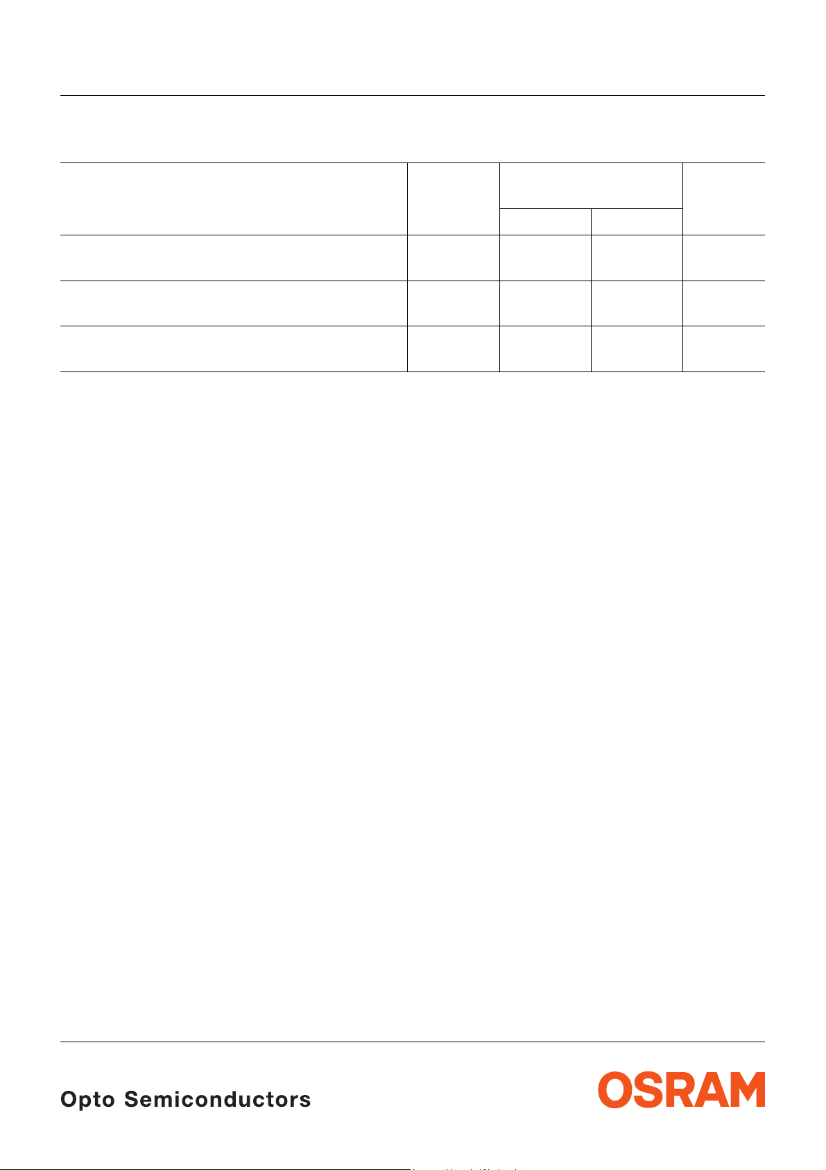
Grenzwerte
Maximum Ratings
SPL MN81G2
Parameter
Parameter
Ausgangsleistung
Optical output power
Tastverhältnis
Duty cycle
Wärmesenkentemperatur
Mount temperature
1)
Betauung des Moduls muss ausgeschlossen werden.
Prevent moisture on the module.
1)
1)
Symbol
Symbol
Werte
Values
min. max.
P
max
– 55 W
dc – 100 %
T
op
5 40 °C
Einheit
Unit
2007-07-18 2
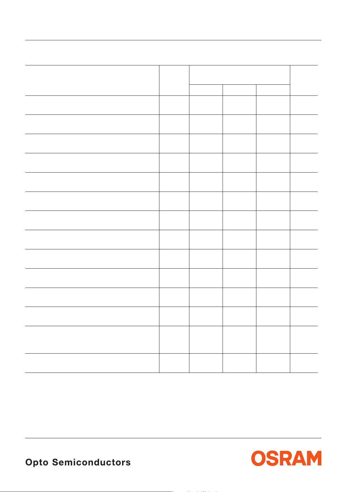
Dioden-Kennwerte (25 °C Wärmesenkentemperatur)
Diode Characteristics (25 °C mount temperature)
SPL MN81G2
Parameter
Parameter
1) 2)
1)
1)
1)
Optische Ausgangsleistung
Optical output power
1)
Emissonswellenlänge
Emission wavelength
1) 2)
Spektrale Breite (Halbwertsbreite)
Spectral width (FWHM)
Schwellstrom
Threshold current
Kennliniensteigung
Slope efficiency
Betriebsstrom
Operating current
Betriebsspannung
Operating voltage
1)
1) 3)
1) 3)
Konversionseffizienz (elektrisch zu optisch)
Conversion efficiency (electrical to optical)
Temperaturkoeffizient der Wellenlänge
Temperature coefficient of wavelength
1) 2)
1) 2)
Symbol
Symbol
Werte
Values
min. typ. max.
P
opt
– 50 – W
λ 805 808 811 nm
Δλ – 3 5 nm
I
th
– 13 16 A
ΔP/ΔΙ – 1.15 – W/A
I
op
V
op
1)
η
1)
con
– 58 – A
– 1.7 – V
48 51 – %
Δλ/ΔT – 0.28 – nm/K
Einheit
Unit
Strahldivergenz senkrecht (Vollwinkel,1/e2)
θ
⊥
– 70 – deg
Beam divergence fast axis (full angle,1/e2)
Strahldivergenz parallel (Vollwinkel,1/e2)
θ
||
– 8 – deg
Beam divergence slow axis (full angle,1/e2)
TE Polarisation
P
TE
90 – – %
TE Polarization
Thermischer Widerstand
R
th
– 0.5 – K/W
(pn-Übergang - Wärmesenke)
Thermal resistance (junction to mount)
Strahlabmessungen am optischen Austritt
h x w – 0.001x10 – mm
2
Beam dimensions at optical output
1)
Werte beziehen sich auf die Standardbetriebsbedingung 50 W cw Ausgangsleistung, 25°C
Wärmesenkentemperatur..
Values refer to standard operating conditions of 50 W cw output power, 25°C mount temperature.
2007-07-18 3

SPL MN81G2
2)
Die zentrale Emissionswellenlänge muss beim spezifizierten Strom kontrolliert werden. Liegt die Wellenlänge
höher als im Testprotokoll spezifiziert, so weist dies auf einen schlechten thermische n Kontakt und eine thermische
Überlastung der Laserdiode hin. Bevor der Laserbetrieb weitergeführt wird, muss der thermische Kontakt
verbessert werden. Die zentrale Emissionswellenlänge schiebt mit 0,28 nm/K.
Check the emission wavelength at the specified current. A much longer wavelength than specified in the test
protocol indicates inefficient or inadequate cooling and thermal overload of the diode laser. Then the cooling has
to be improved before continuing laser operation. The emission wavelength shifts with 0.2 8 nm/K.
3)
Das Anlegen einer Spannung in Sperrrichtung der Laserdiode muss ausgeschlossen werden.
Reverse voltage has to be excluded.
2007-07-18 4

Optische Kennwerte (cw, 25°C Wärmesenkentemperatur)
Optical Characteristics (cw, 25°C mount temperature)
SPL MN81G2
Optical power P
V
V
2.0
1.5
1.0
0.5
0
0A
10 20 30 40 50 70
and voltage V vs. current I
opt
OHW03962
V
P
opt
70
W
60
50
40
30
20
10
0
I
Optical Spectrum @ 50 W
120
P
opt
%
I
rel
100
80
60
40
20
0
780
790 800 810 830
OHW03959
nm
λ
Wallplug efficiency
60
%
η
con
50
40
30
20
10
0
0A
10 20 30 40 50 70
η
vs. current I
con
OHW03963
I
2007-07-18 5

Maßzeichnung
Package Outlines
7.4 (0.291)
M2
(Shorting place)
M2
SPL MN81G2
11.7 (0.461)
10.6 (0.417)
12.45 (0.490)M3 (Cathode)
4 x ø4.4 (0.173)
ø2.8 (0.110)
depth 2.4 (0.094)
Anode
24.9 (0.980)
21.3 (0.839)
12.3 (0.484)
6.1 (0.240) 14 (0.551)
Maße in mm (Zoll) / Dimensions in mm (inch).
Allgemeintoleranz / General Tolerance: +/- 0.2 mm (0.008 inch)
+
-
18.5 (0.728)
24.9 (0.980)
3.2 (0.126)
14.2 (0.559)
7.9 (0.311)
Optical beam
GDOY7030
2007-07-18 6

SPL MN81G2
Published by
OSRAM Opto Semiconductors GmbH
Wernerwerkstrasse 2, D-93049 Regensburg
www.osram-os.com
© All Rights Reserved.
The information describes the type of component and shall not be considered as assured chara cteristics.
Terms of delivery and rights to change design reserved. Due to technical requirements components may contain
dangerous substances. For information on the types in question please contact our Sales Organization.
Packing
Please use the recycling operators known to you. We can also help you – get in touch with your nearest sales office.
By agreement we will take packing material back, if it is sorted. You must bear the costs of transport. For packing
material that is returned to us unsorted or wh ich we are not obliged to accept, we shall hav e to invoice you for any costs
incurred.
Components used in life-support devices or systems must be expressly authorized for such purpose! Critical
components 1 , may only be used in life-support devices or systems 2 with the express written approval of OSRAM OS.
1
A critical component is a component used in a life-support device or sys tem whose failure can reasonably be expected
to cause the failure of that life-support device or system, or to affec t its safety or e ffectiveness of that dev ice or system.
2
Life support devices or systems are intended (a) to be implanted in the h uman body, or (b) to support and/or maintain
and sustain human life. If they fail, it is reasonable to assume that the health of the user may be endangered.
2007-07-18 7
 Loading...