

查询SFH9300供应商查询SFH9300供应商
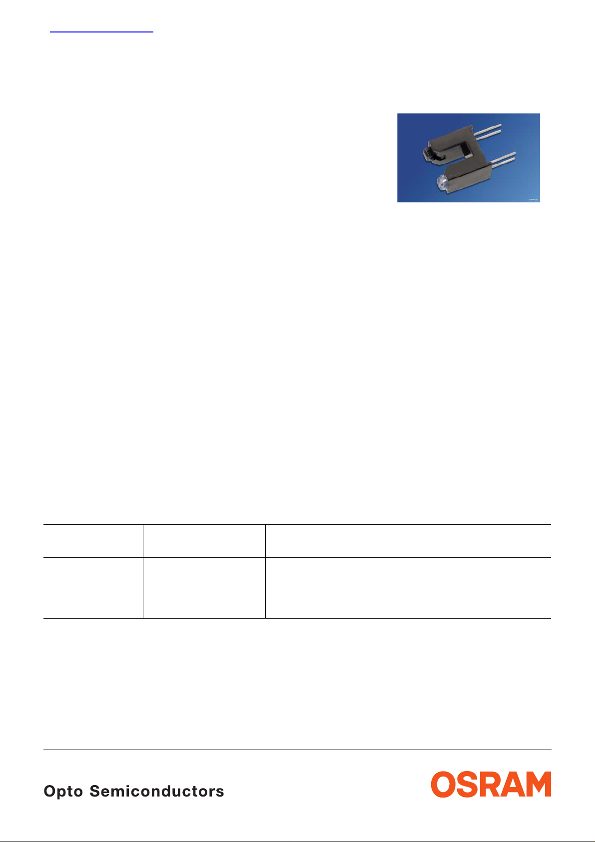
Gabellichtschranke
Slotted Interrupter
SFH 9300
Wesentliche Merkmale
• Kompaktes Gehäuse
• GaAs-IR-Sendediode (950 nm)
• Si-Fototransistor mit Tageslichtsperrfilter
• Einfache Unterscheidbarkeit von Sender
(transparentes Gehäuse) und Empfänger
(schwarzes Gehäuse)
Anwendungen
• Geschwindigkeitsüberwachung
• Motorsteuerung
• Überwachung des Papiervorschubs in
Druckern, Kopier- und Faxgeräten
• Speicherlaufwerke
• Steuerung des Druckkopfes in Druckern
• Münzdetektion
• Optoelektronische Schalter
Typ
Type
Bestellnummer
Ordering Code
Features
• Compact type
• GaAs infrared emitter (950 nm)
• Silicon phototransistor detector with
daylight-cutoff filter
• Easy identification of emitter (clear component
package) and transistor (black component
package)
Applications
• Speed control
• Motor control
• Monitoring of paper feed in printers, copiers,
facsimiles
• Disk drives
• Control of print head in printers
• Coin detection
• Optoelectronic switches
Gehäuse
Package
SFH 9300 Q62702-P5019 Schwarzes Polykarbonat Plastikgehäuse, Anschlüsse
im 2,54-mm Raster
Polycarbonate plastic material housing, solder tabs
2.54-mm (1/10”) spacing
2001-02-22 1
Grenzwerte TA = 25 °C
Maximum Ratings
SFH 9300
Bezeichnung
Parameter
Sender (GaAs-Diode)
Emitter (GaAs Diode)
Sperrspannung
Reverse voltage
Durchlaßstrom
Forward current
Verlustleistung
Power dissipation
Wärmewiderstand
Thermal resistance
Empfänger (Si-Fototransistor)
Detector (Silicon Phototransistor)
Kollektor-Emitter-Spannung
Collector-emitter voltage
Symbol
Symbol
V
R
I
(DC) 60 mA
F
P
tot
R
thJA
V
CE
Wert
Value
5V
100 mW
280 K/W
30 V
Einheit
Unit
Kollektor-Emitter-Spannung, (
Collector-emitter voltage, (
t ≤ 2 min)
Emitter-Kollektor-Spannung
Emitter-collector voltage
Kollektorstrom
Collector current
Verlustleistung
Total power dissipation
Wärmewiderstand
Thermal resistance
t ≤ 2 min)
V
CE
V
EC
I
C
P
tot
R
thJA
70
7
50 mA
150 mW
280 K/W
2001-02-22 2
SFH 9300
Grenzwerte
T
= 25 °C
A
Maximum Ratings (cont’d)
Bezeichnung
Parameter
Gabellichtschranke
Slotted Interrupter
Lagertemperatur
Storage temperature range
Betriebstemperatur
Operating temperature range
Elektrostatische Entladung
Electrostatic discharge
Kennwerte
T
= 25 °C
A
Characteristics
Bezeichnung
Parameter
Symbol
Symbol
T
stg
T
op
Wert
Value
Einheit
Unit
– 40 … + 85 °C
– 40 … + 85
ESD 2 kV
Symbol
Symbol
Wert
Value
Einheit
Unit
Sender (GaAs-Diode)
Emitter (GaAs Diode)
Wellenlänge der Strahlung
Wavelength of peak emission
Durchlaβspannung
Forward voltage
I
= 20 mA, tp = 20 ms
F
Sperrstrom
Reverse current
V
= 5 V
R
Kapazität
Capacitance
V
= 0 V, f = 1 MHz
R
λ
V
I
C
peak
F
R
0
950 nm
1.2 (≤ 1.4) V
0.01 (≤ 1) µA
16 pF
2001-02-22 3

T
Kennwerte
= 25 °C
A
Characteristics (cont’d)
SFH 9300
Bezeichnung
Parameter
Empfänger (Si-Fototransistor)
Detector (Silicon Phototransistor)
Wellenlänge der max. Fotoempfindlichkeit
Wavelength of max. sensitivity
Spectr. Bereich der Fotoempfindlichkeit
Spectral range of sensitivity
S = 10% of S
max
Kapazität
Capacitance
V
= 0 V, f = 1 MHz, E = 0
CE
Dunkelstrom
Dark current
V
= 20 V
CE
Gabellichtschranke
Slotted Interrupter
Symbol
Symbol
λ
S max
Wert
Value
Einheit
Unit
920 nm
λ 840 … 1080 nm
C
I
CEO
CE
6.5 pF
2 (≤ 50) nA
Kollektor-Emitterstrom
Collector-emitter current
I
= 20 mA; VCE = 5 V
F
Kollektor-Emitter-Sättigungsspannung
Collector-emitter-saturation voltage
I
= 20 mA; IC = 0.3 mA
F
Anstiegs- und Abfallzeit
Rise and fall time
V
= 5 V, IC = 1 mA, RL = 1 kΩ
CC
I
CE min.
I
CE typ.
V
CE sat
t
r
t
f
> 1 mA
≤ 0.4 V
13
17
µs
µs
2001-02-22 4

SFH 9300
Forward Current IF = f (VF)
Single pulse,
4
10
mA
Ι
F
3
10
2
10
1
10
0
10
-1
10
-2
10
0
t
= 20 µs
p
12340.5 1.5 2.5 V
OHF00367
V
F
Total Power Dissipation for
Emitter and Detector
160
P
Detector
tot
140
120
Emitter
100
P
tot
OHF00410
= f (TA)
Max. Permi ssible F orward Cur rent
I
= f (TA)
F
90
Ι
F
mA
70
60
50
40
30
20
10
0
0
R
thJA
20 40 60 80 120
= 280 K/W
OHF00372
C
T
A
Dark Current I
V
= 20 V, E = 0
CE
3
10
Ι
CEO
2
10
1
10
0
10
-1
10
0nA20 40 60 80 100˚C
CEO
= f (TA)
OHF00380
T
A
80
60
40
20
0
02040
60 80 100˚C
T
A
2001-02-22 5

Maßzeichnung
Package Outlines
3.78 (0.149)
3.52 (0.139)
0.5 (0.020)
0.3 (0.012)
7.82 (0.308)
7.42 (0.292)
10.80 (0.425)
10.54 (0.415)
optical axis
3.31 (0.130)
2.81 (0.111)
10.55 (0.415)
0.6 (0.024)
10.05 (0.396)
0.4 (0.016)
2.54 (0.100)
6.6 (0.260)
6.1 (0.240)
6.0 (0.236)
6.6 (0.260)
12.05 (0.474)
11.55 (0.455)
SFH 9300
Pin Configuration
2.75 (0.108)
3.25 (0.128)
LED
(clear encapsulation) (black encapsulation)
2.35 (0.093)
1.85 (0.073)
Maße werden wie folgt angegeb en: m m (inch) / Dimensions are specified as follows: mm (inch).
Anode
(top view)
Phototransistor
Emitter
CollectorCathode
GPXY6986
2001-02-22 6

Löthinweise
Soldering Conditions
SFH 9300
Bauform
Type
Tauch-, Schwalllötung
Dip, Wave Soldering
Peak Temp.
(solderbath)
Max. Time in
Peak Zone
Reflowlötung
Reflow Soldering
Peak Temp.
(package
Max. Time in
peak zone
Kolbenlötung
Iron Soldering
(Iron temp.)
temp.)
SFH 9300 260 °C 10 s n. a. – 300 °C < 5 s
Published by OSRAM Opto Semiconductors GmbH & Co. OHG
Wernerwerkstrasse 2, D-93049 Regensburg
© All Rights Reserved.
Attention please!
The information describes the type of component and shall not be c onsidered as assured characteristics.
Terms of delivery and rights to change design reserved. Due to technical requirements components may contain
dangerous substances. For information on the types in question please contact our Sales Organization.
Packing
Please use the recycling operators k nown to you . We can als o help you – get in touch wit h your near est sales offic e.
By agreement we will take p acking material back, if it is sorted. You m ust bear the costs of transport. For packing
material that is returned to us unsorted or which we are not obliged to accept, we shall have to invoice you for any costs
incurred.
Components used in life-support devices or systems must be expressly authorized for such purpose! Critical
components
1
A critical component is a co mponent usedin a l ife-support devi ce or system whose failure can re asonably be expec ted
to cause the failure of that life-support device or system, or to affect its safety or effectiveness of that device or system.
2
Life support devices or systems are intend ed (a) to be impl anted i n t he human b ody , or (b ) to supp ort a nd/or ma inta in
and sustain human life. If th ey fail , it is rea so nable to assume that the health of the user m ay be endangered.
2001-02-22 7
1
, may only be used in life-support devices or systems 2 with the express written approval of OSRAM OS.
 Loading...