

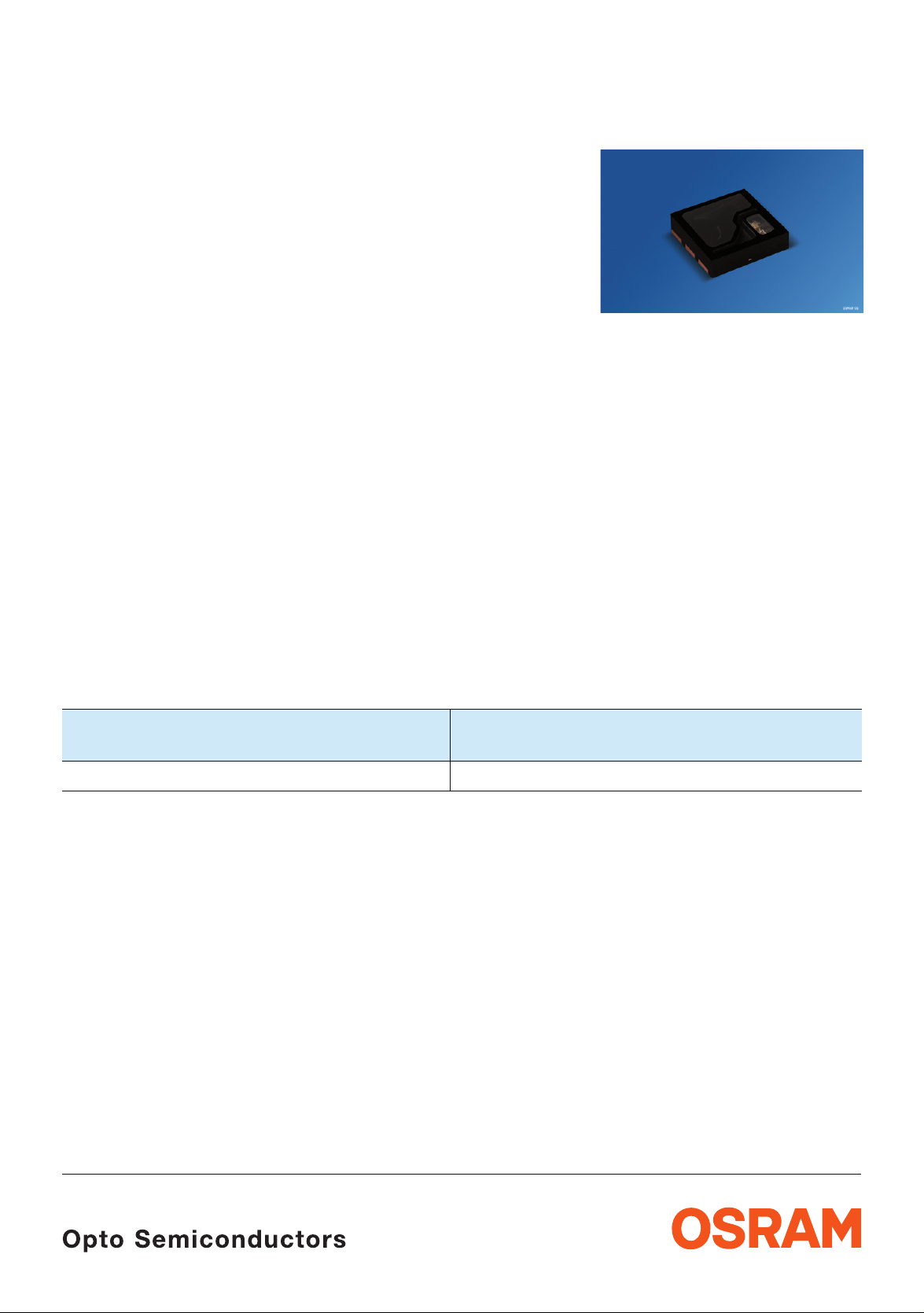
OSRAM SFH 7741 Technical data
Näherungssensor
Proximity Sensor
Lead (Pb) Free Product - RoHS Compliant
SFH 7741
Wesentliche Merkmale
• Typ. Arbeitsabstand: 30 mm
• Optohybrid mit Schmitt-Trigger Ausgang, open
drain
• Extrem niedriger Stromverbrauch
• Sehr kleines SMD Gehäuse
• Hohe Umgebungslicht Unterdrückung
• Ohne externe Linse ist der SFH 7741
augensicher entsprechend der IEC 62471
Norm
Anwendungen
• Näherungssensor für kurze Entfernungen
Typ
Type
SFH 7741 Q65110A7073
Features
• Typ. Working distance: 30 mm
• Opto hybrid with Schmitt trigger output, open
drain
• Extremly low power consumption
• Very small SMD package
• High ambient light suppression
• Without external lenses the SFH 7741 is Eye
Safe according to the IEC 62471 standard
Applications
• Short range proximity sensor
Bestellnummer
Ordering Code
An application note is available for this product.
Please contact your appropriate OSRAM sales partner
2010-02-04 1
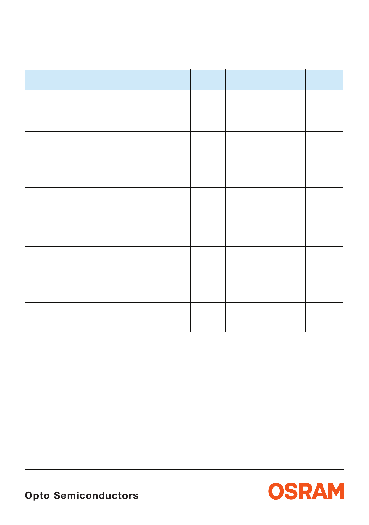
Grenzwerte Maximum Ratings
SFH 7741
Bezeichnung
Parameter
Lagertemperatur
Storage temperature
Versorgungsspannung
Supply voltage
Externe Spannung an Pin
External voltage at pin
Out
Prog
Test
Anode LED
Sink current durch den Ausgangstransistor
Sink current through output transistor
(please see figure 1)
Vorwärtsstrom
1)
Forward current
(please see figure 1)
Elektrostatische Entladung
Electrostatic discharge
- Human Body Model
(according to: JESD22-A114E; Class2)
- Machine Model
(according to: JESD22-A115A; Class B)
Symbol
Symbol
T
stg
V
dd
V
out
I
sink
I
f
ESD
Wert
Value
min: – 40
Einheit
Unit
°C
max: + 85
0 - 6 V
V
0 - 4.5
0 - 4.5
0 - 4.5
0 - 1.5
10 mA
60 mA
2
200
kV
V
latch up protection
latch up protection
(according to: EIA/JESD78 Class 1)
1)
Der Vorwärtsstrom If durch die LED ist abhängig von Vdd und R
* The forward current If depends on Vdd and R
2010-02-04 2
as in the following formula:
prog
wie folgt:
prog
20 mA
V
dd
⎛⎞
------------------
If10mA
+=
⎝⎠
R
prog
6×
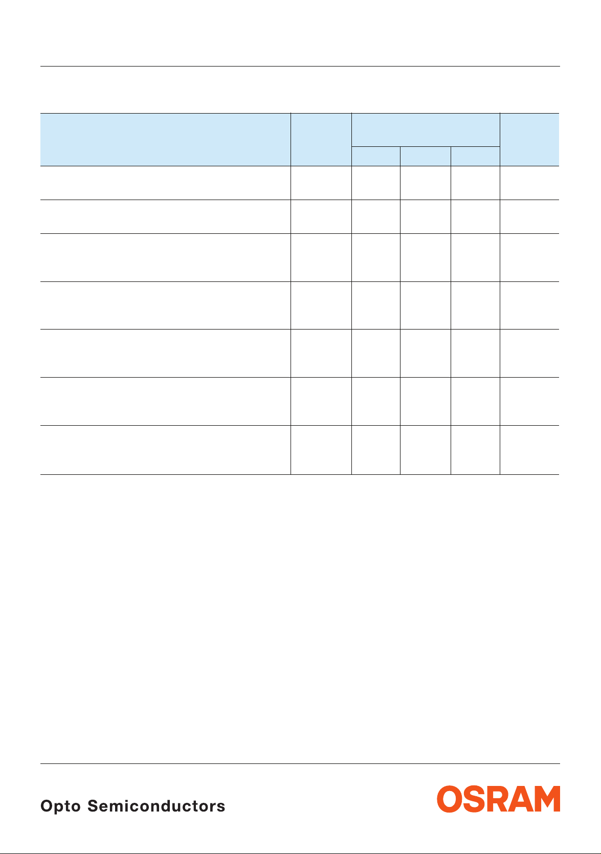
Empfohlene Betriebsbedingungen Recommended Operating Conditions
SFH 7741
Bezeichnung
Parameter
Betriebstemperatur
Operating temperature
Versorgungsspannung
Supply voltage
Ausgangsspannung
Output voltage
(please see figure 1)
Rauschen der Versorgungsspannung
Supply voltage ripple
frequency range 0...20kHz
Pull-up Widerstand
Pull-up resistor
(please see figure 1)
Abblock Kondensatoren
Bypass capacitors
(please see figure 1)
Symbol
Symbol
Wert
Value
Einheit
Unit
min. typ. max.
T
op
V
dd
DV
dd
1)
dV
dd
R
pull-up
C
bypass
- stabilisation
- HF
– 20 + 85 °C
2.4 3.6 V
1.7 3.6 V
200 mV
10 1000 kΩ
>1
10 - 100
µF
nF
Max. Umgebungslicht
Max. ambient light
Normlicht / Standard light A
1)
Der Emitter wird mit 10mA bis 60mA gepulst betrieben; das bedeutet, dass jeder Widerstand in Serie zu V
Spannungsabfall in der Versorgungsleitung verursacht. Es wird empfohlen, diesen Serienwiderstand so klein zu
halten, dass max dV
Labor ist vom Einsatz geregelter Spannungsversorgungen abzusehen. Durch das Einschalten der IRED wird die
Quelle kurzzeitig belastet. Diese Belastung kann zu Spannungsschwankungen der Quelle führen, die wiederum die
Funktion des SFH 7741 beeinträchtigen können. Im Normalbetrieb (Akku, Batterie, stabilisierte Netzteile) tritt dieser
Effekt nicht auf.
The emitter is driven with 10 mA to 60 mA in pulsed mode; this means, that any series resistance on the Vdd line
causes a voltage drop at the power pin. It is recommended to keep the series resistance low, so that max dV
exceeded. When testing the SFH 7741 sensor in the lab, please do not use regulated voltage supplies. The IR
emitter pulse is a high, short load for the power supply. This load can influence the stability of the output voltage; this
instability will influence the operation of the SFH 7741. This effect does not occur during normal operation of the
sensor with batteries, storage batteries, or stabilized voltage supplies.
nicht überschritten und min Vdd nicht unterschritten wird. Beim Betrieb des SFH 7741 im
dd
E
V
Vdd < 3V
Vdd > 3V
1000
2000
lux
einen
dd
is not
dd
2010-02-04 3
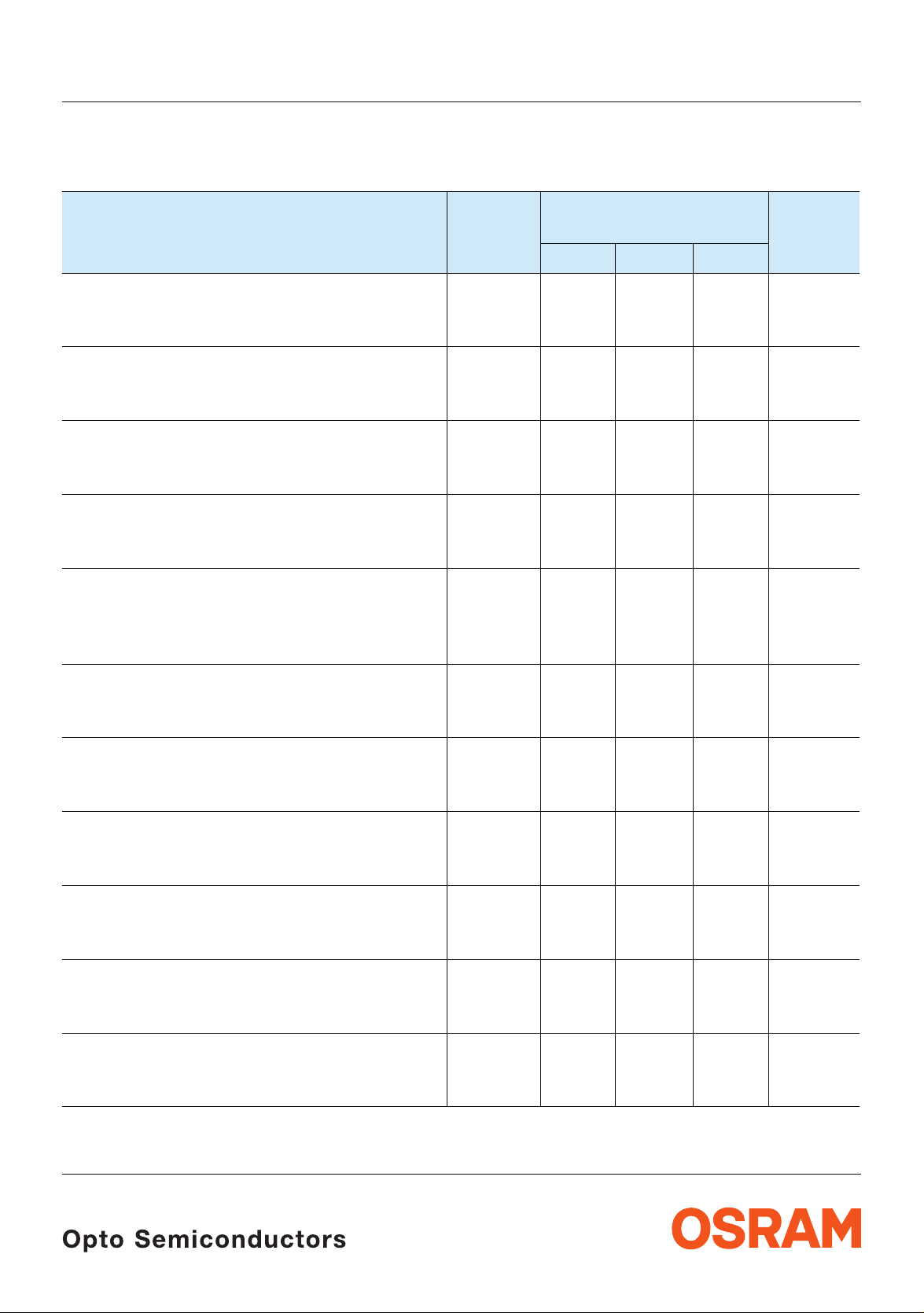
Kennwerte (Ta = 25°C)
Characteristics
SFH 7741
Bezeichnung
Parameter
Minimale Betriebsspannung für Startphase
Minimum required supply voltage for start-up
(please see figure 2)
Länge der Startphase
Start-up time
(please see figure 2)
Mess-Wiederholzeit
Measurement refresh time
(please see figure 3)
LED „An“ Zeit
LED „ON“ Time
(please see figure 3)
Schaltabstand
Operating distance
(R
= 470 Ω, Vdd = 3V,
Prog
KODAK White Paper R=90%)
Symbol
Symbol
Wert
Value
Einheit
Unit
min. typ. max.
V
dd, start
t
start
t
refresh
t
pulse
0.8 2.0 V
60 90 120 ms
60 90 120 ms
30 45 60 µs
d 30 mm
Durchschnittliche Stromaufnahme1)
Mean current consumption
(R
= h, Vdd = 3V)
Prog
1)
Maximale Stromaufnahme
Maximum current consumption
(R
= h, Vdd = 3V)
Prog
Durchschnittliche Stromaufnahme
Mean current consumption
(R
= 470 Ω, Vdd = 3V)
Prog
1)
1)
Maximale Stromaufnahme
Maximum current consumption
(R
= 470 Ω, Vdd = 3V)
Prog
Ausgangsleckstrom „high“
Output leakage current „high“
DVdd = 2.2V
Ausgangsspannung „low“
Output voltage „low“
DVdd = 2.2V; R
pullup
= 270 Ω
I
dd, mean
I
dd, max
I
dd, mean
I
dd, max
I
out, H
V
out, L
25 50 μA
10 20 mA
45 75 μA
50 65 mA
5 400 nA
0.1 0.5 V
2010-02-04 4
Kennwerte (Ta = 25°C)
Characteristics
SFH 7741
Bezeichnung
Parameter
Symbol
Symbol
min. typ. max.
Wellenlänge der max. Fotoempfindlichkeit
λ
S, max
Wavelength of max. sensitivity
Spektraler Bereich der Fotoempfindlichkeit
S = 10% von S
max
λ 730 1080 nm
Spectral range of sensitivity
S = 10% of S
Wellenlänge der Strahlung des Emitters
max
λ
peak
Wavelength at peak emission
I
= 10 mA
F
Spektrale Bandbreite des Emitters bei 50% von
I
max
Spectral bandwidth of the emitter at 50% of I
Δλ 30 nm
max
IF = 10 mA
1)
gepulster Betrieb: Dauer LED an: ~44µs / Dauer LED aus: ~90ms
pulsed operating mode: LED on time: ~44µs / LED off time: ~90ms
Wert
Value
Einheit
Unit
880 nm
850 nm
2010-02-04 5
 Loading...