

Page 1

www.osram.dewww.osram.com June 2009
QUICKTRONIC® DALI/DIM Technical Guide.
Dimmable Electronic Control Gears for Fluorescent Lamps.
•
DALI/1…10 V Basics
•
Product Overview and Features
•
Installation and Operation Instructions
Page 2

Contents
1 Introduction .................................................................4
1.1 Dimmable lighting systems ..............................................4
1.1.1 Economy .........................................................................4
1.1.2 Lighting comfort ..............................................................5
1.1.3 Reliability/Safety .............................................................. 6
1.1.4 The right control unit for every application ....................... 6
2 Overview of dimmable control gear ........................... 7
2.1 Block diagrams of a digital/analog dimmable ECG .......... 7
2.2 DALI in comparison to 1…10 V and EIB/LON..................8
2.2.1 DALI and 1…10 V characteristics ....................................8
2.3 DALI installation & features ............................................ 10
2.3.1 Simplified installation .....................................................10
2.3.2 Construction site mode ................................................. 10
2.3.3 Benefits of DALI ECG in group assignment....................10
2.3.4 Integrated scene memory ..............................................10
2.3.5 Status report from the ECG ........................................... 10
2.3.6 No more switching relays ..............................................11
2.3.7 Addressing is not essential ............................................11
2.4 Installation and wiring instructions ................................. 11
2.4.1 Burning-in instructions/Cable insulation .........................11
2.4.2 Safety instructions .........................................................13
2.4.3
2.4.4 Operation of multiple ECGs in a luminaire ......................16
2.4.5 Wiring examples of dimmable electronic control gear: ...17
2.5 The DALI interface – technical details ............................ 18
2.5.1 The principle of the DALI system ...................................18
2.5.2 DALI topology ...............................................................19
2.5.3 DALI parameters in the ECG ......................................... 19
2.5.4 Requirements to be met by the transmission cable .......20
2.5.5 Wiring diagram for DALI ECGs ...................................... 20
2.6 DALI data transmission .................................................22
2.6.1 Behavior in the event of a fault.......................................23
2.7 The DALI dimming curve ...............................................23
2.7.1 Brief overview of the most important dimming values ....24
2.8 Features of the digital interface ......................................25
2.9 Characteristics of the 1…10 V interface ........................26
2.9.1 The 1…10 V dimming curve ..........................................28
Radio interference suppression of dimmable luminaires
...14
3 Additional characteristics of dimmable electronic
control gear from OSRAM ......................................... 29
3.1 OSRAM DALI/1…10 V ECGs: Added-value through
intelligent features .........................................................29
3.2 OSRAM DALI ECGs and TouchDIM interface ................ 30
3.2.1 Wiring and line compensation .......................................31
3.2.2 Operating parameters for TouchDIM..............................32
3.2.3 Compensation of interference........................................32
3.2.4 TouchDIM operation ......................................................33
1
Page 3

3.2.5 Operating modes with TouchDIM .................................. 33
3.2.6 Asynchronism/Automation of the system .......................36
3.2.6.1 Prevention/remedying of asynchronism ......................... 36
3.2.6.2 Synchronization .............................................................36
3.2.7 Behavior after mains voltage failure ...............................37
3.3
3.3.1 Mains failure at the sub-distributor (UV) .........................39
3.3.2 Mains failure at the main distributor (HV) ........................ 40
3.3.4 Emergency DC operation of the lighting system without
3.3.5 QTi DALI: Advantages in emergency lighting
3.4 OSRAM DALI LUMINAIRE TOOL (DLT) ..........................40
3.5 Basic circuits of 1…10 V control gear ............................42
3.5.1 1…10 V: Staircase operating modes ............................. 43
3.5.1.1 Applications ..................................................................43
3.5.1.2 Control via analog output .............................................. 45
3.5.1.3 Interface circuit ..............................................................45
3.5.1.4 Control via instabus EIB ................................................ 46
3.6 Special wiring diagrams, tips and tricks .........................46
3.6.1 Temperature-dependent control ....................................46
3.6.2 Limits of the control voltage ...........................................47
3.6.3 Cable length of the 1…10 V control line ........................48
3.6.4 1…10 V DIM ECGs and emergency lighting ..................48
3.7 Terminals/Cable cross sections/Wire stripping lengths ...49
3.7.1 Inserting and releasing the connection cables ...............50
3.7.2 Cable cross sections ....................................................51
3.7.3 Basic insulation .............................................................51
3.7.4 Holders ......................................................................... 51
3.7.5 Master-slave circuit .......................................................51
3.7.6 Minimum reflector gaps .................................................51
3.8 Temperature response of dimmable ECGs from
3.8.1 Intelligent thermal management in hot luminaires ........... 52
3.8.2 Color temperature .........................................................56
3.8.3 Outdoor applications .....................................................56
3.8.4 Functional test of luminaires ..........................................57
3.9 Dimming of amalgam lamps ..........................................57
3.9.1
3.9.2 The benefits of amalgam technology ............................. 61
OSRAM DALI ECGs in emergency lighting applications ....
monitoring module ........................................................ 40
applications ...................................................................40
OSRAM .........................................................................52
Dynamic dimming procedures with amalgam lamps ....... 60
37
4
5 Dimming of compact fluorescent lamps .................64
5.1 Unique features of the new OSRAM CFL ECGs .............65
6 The DALI Activity Group (AG DALI) ...........................67
System energy consumption and dimmer setting ...
2
63
Page 4

7 Tender documents .....................................................68
8 Frequently asked questions (FAQ) ........................... 72
8.1 Part of DALI ..................................................................72
8.1.1 TouchDIM .....................................................................72
8.1.2 DALI in general ..............................................................73
8.1.3 DALI to 1…10 V converter ............................................76
8.1.4 Troubleshooting TouchDIM mode .................................. 76
8.1.5 Troubleshooting DALI controllers ................................... 77
8.1.6 DALI to 1…10 V converter ............................................77
8.2 Part of 1…10 V DIM ECGs ............................................77
8.2.1 Troubleshooting 1…10 V ...............................................79
9 Appendix .....................................................................80
9.1 Starting currents and max. number of ECGs in
automatic cutouts ......................................................... 80
9.1.1 Minimum triggering levels for B/C characteristic ............ 80
9.2 DALI fade time and fade rate .........................................81
9.3 Lamp wiring ..................................................................81
9.4 Operating parameters of the ECG lamp combinations ...84
9.5 Energy classifications ....................................................85
9.6 The DALI standard (IEC 62386) at a glance ................... 86
Index .....................................................................................87
3
Page 5
1 Introduction
1.1 Dimmable lighting systems
Dimmable electronic control gears (DIM ECGs) are playing an
increasingly important role in all areas of application of modern
lighting technology. Dimmable ECGs from OSRAM, integrated in a
building management system, form the heart of intelligent lighting systems which save up to 80 % of energy compared to conventional
electronic control gears. The reason for this is that many requirements
of a lighting system are simple and elegant to realize by means of light
control. Economy, lighting comfort, reliability and safety are the driving
forces here.
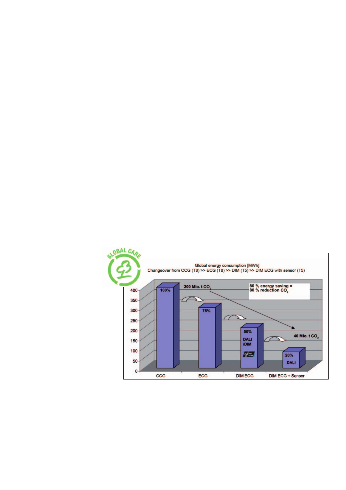
1.1.1 Economy
Intelligent energy-saving concepts in building management lower the
lighting costs many times over:
• Up to 50 % less power consumption compared to operation with
magnetic, conventional electronic control gears (CCG)
• More than 50 % longer lamp lifetime compared to operation with
ECG and low-loss electronic control gears (LLG) through defined
lamp operation ! Lower maintenance costs
• Lowering of energy costs for air conditioning systems by reducing
the cooling load
Figure 1: Global energy saving potential with dimmable electronic
control gear
4
Page 6
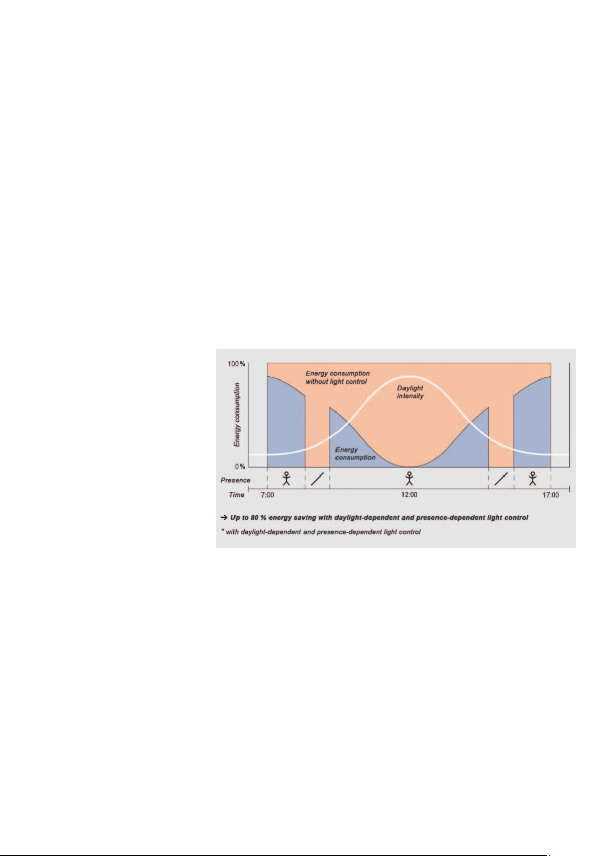
1.1.2 Lighting comfort
Lighting situations at the touch of a button (lighting scenes), also with
integrated presence detection and daylight/time-dependent control,
increase lighting comfort. The features of a high-quality dimmable
ECG also include:
• Flicker-free ignition
• Comfortable, continuously dimmable (1(3)…100 %) and flicker-free
lighting without stroboscopic effects
• Virtually noise-free, no irritating humming of chokes (CCG/LLG)
• No flashing of defective lamps
• Automatic restart after lamp replacement
• Easy-to-use, feedback messages to the control unit and configuration of personal lighting values create individuality
Figure 2: Energy saving and increased lighting comfort through inte-
grated presence detection with daylight/time-dependent control
This has been made possible mostly thanks to technical develop-
ments. Modern dimmable ECGs with digital (DALI = Digital Address-
able Lighting Interface) or analog (1…10 V) interface in combination
with corresponding control elements, control units and sensors create
the preconditions for simple and low-cost realization of more efficient
and convenient lighting systems.
5
Page 7

1.1.3 Reliability/Safety
•
•
•
•
•
Reliability and safety play a crucial role in the use of electronic control
gear. Key features of high-quality ECGs include:
• Preheating of both lamp filaments
• Dependable lamp ignition to an ambient temperature of -20 °C
• Dependable lamp operation in the temperature range of -20 °C to
1
75 °C
• Dependable shutdown of the ECG in the event of a fault and at
"End of Life" (EoL)
• Compliance with all current applicable ECG standards:
• Safety (EN61347)
• Performance (EN60929)
• Harmonic current emissions (EN61000-3-2)
• Radio interference suppression from 9 kHz to 300 MHz
(EN55015: 2006 + A1:2007)/CDN measurement
• Immunity (EN61547)
1.1.4 The right control unit for every application
Dimmable ECGs have a very wide range of uses. Some examples of
applications are offices and industrial buildings with light-dependent
control, conference and assembly rooms with lighting for the particular situation or CAD offices and switch rooms with individually adjustable light levels. The core of the lighting system are the dimmable
QUICKTRONIC Intelligent
®
ECGs from OSRAM with DALI or 1…10 V
interface (QTi DALI/DIM) for the operation of compact and fluorescent
lamps. These are controlled by a control unit, a sensor or a simple
button/rotary dimmer switch. The choice of the right dimming components for controlling the lighting depends on the desired application.
The requirement profile of the dimmable lighting system must, therefore, be defined in detail.
1
at a dimming setting of 100 % → max. ECG output to the lamp
6
Page 8

2 Overview of dimmable
electronic control gears
2.1 Block diagrams of a digital/analog dimmable ECGs
2
a) Digital dimmable ECG with DALI interface
b) Analog dimmable ECG with 1…10 V interface
Figure 3: EMC filters and safety shutdown are important elements of
high-quality dimmable electronic control gears.
2
• Power Factor Correction: Correction of the line current harmonics
• HF half-bridge generator (40 kHz – 120 kHz) with resonance circuit
• Safety shutdown incl. “End of Life“ detection
• Cs: Storage capacitor
• EMC filter for HF interference signals from 9 kHz to 300 MHz
7
Page 9
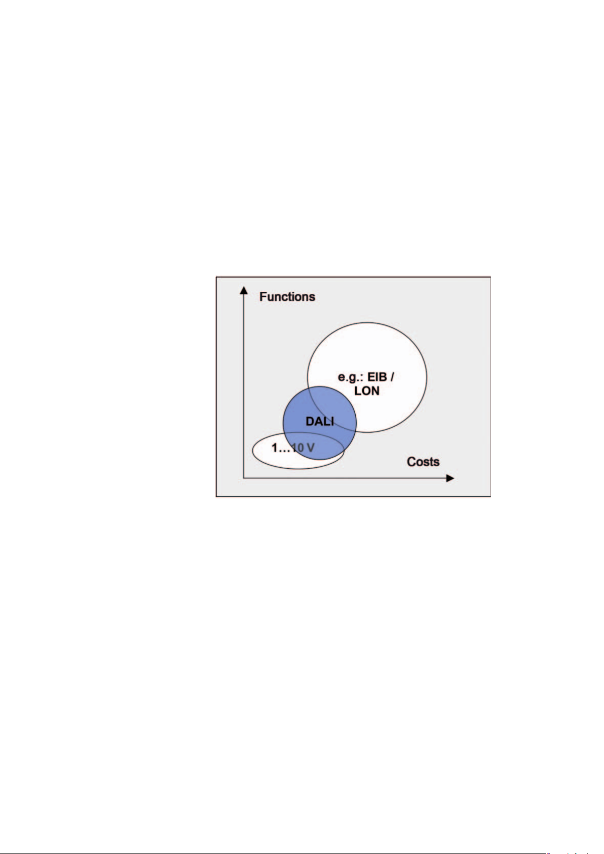
2.2 DALI in comparison to 1…10 V and EIB/LON
What modern lighting technology needs is a system that is as flexible
as it is simple, a system that focuses on room-based lighting
control with just a few low-cost components, minimal wiring and a
user-friendly operating concept. The lighting industry has therefore developed a new digital communication standard for lighting systems:
DALI closes the gap between the former 1…10 V technology and
complex bus systems. DALI can be used either as a very simple local solution or as a subsystem integrated in a building management
system.
Figure 4: Overview of 1…10 V, DALI and EIB/LON
With traditional electrical installations and even with the widely used
analog 1…10 V interface such requirements are very difficult to meet
and involve a great deal of time, effort and expense. A large number
of components have to be used to enable a programmed scene to
be changed, to provide flexible grouping at the same time and then
possibly to integrate these settings in a daylight-dependent control
system.
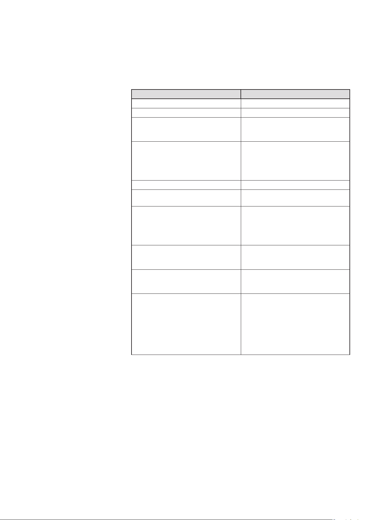
2.2.1 DALI and 1…10 V characteristics
The basis for any control system are the defined physical proper-
ties at the interface and the properties of the interface cables as the
transmission medium. Thanks to a high signal-to-noise ratio and wide
ranges for digital “low” and “high”, it is virtually impossible with DALI
for data transfer to be affected by interference. Consequently, there is
no need to use shielded control cables. As in the case of the 1...10 V
interface, the mains and control inputs in the ECGs are electrically
isolated. A conscious decision was taken not to use safety extra-low
voltage (SELV) in order to offer low-cost installation without additional
8
Page 10
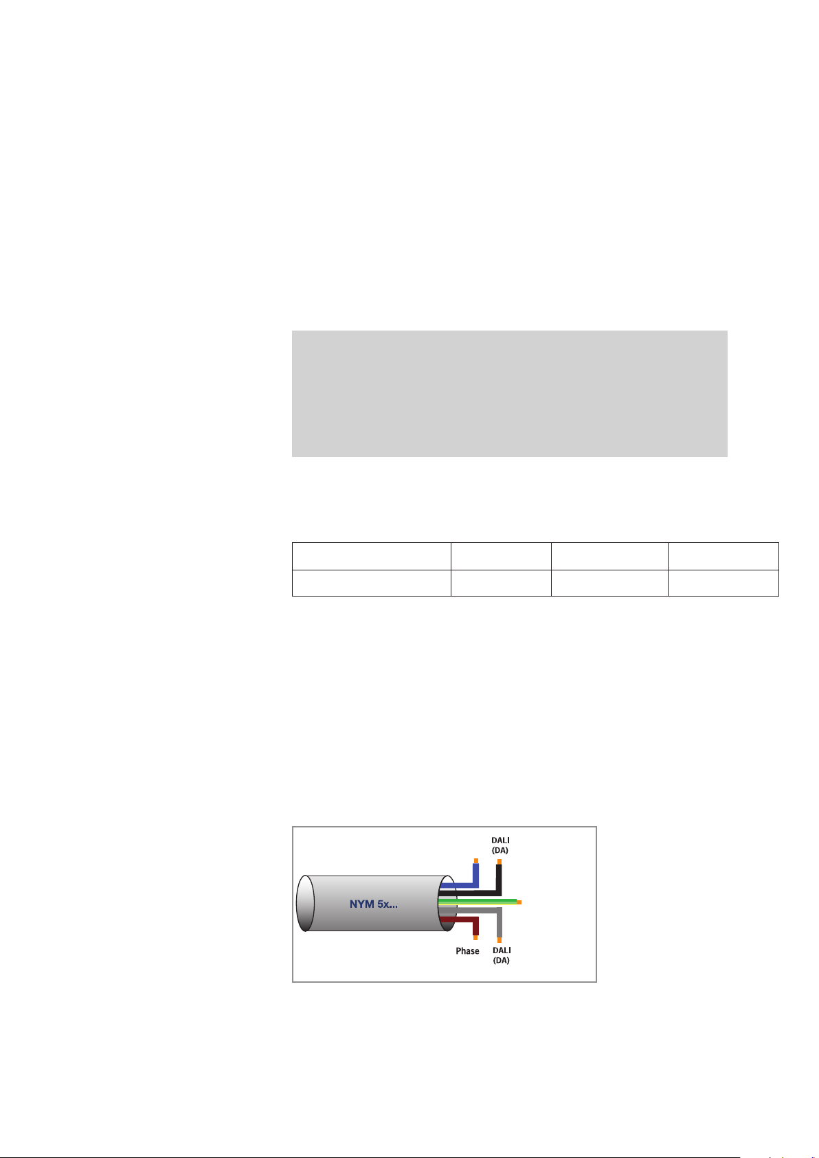
special lines or cable penetrations. A 5 x 1.5 mm2 NYM cable, for
example, can be used for the mains feed and DALI.
1…10 V DALI
Potential-free control input Potential-free control input
Two-wire line (with +/- polarity) Two-wire line (polarity-free)
Dimming curve, luminous flux linear Dimming curve, optically linear
(= logarithmic), matching the sensitivity of
the eye
Non-addressable
• Wiring acc. to groups required
Not possible Scene memory (max. 16)
Not possible
Not possible Status messages of the DALI controllers
Addressing possible:
• Individual (max. 64 addresses)
• In groups (max. 16)
• All together
! No wiring acc. to groups
Individual addressing of the DALI ECG
• Lamp faults
• Operating life
• Dimmer setting
Not possible Individual dimming options
• Storing the last dimming value as a starting value
External mains voltage switch
(e.g.: relay)
Common mains supply and control line
possible through:
Basic insulation
Integrated mains voltage switch (switchoff of the ECG via DALI interface, no relay
necessary)
Common mains supply and control line
possible through mains:
TouchDIM interface
• Control with mains voltage
vation of the mains voltage phase
! No separate bus line
• Conventional, commercially available
buttons
Table 1: Comparison between 1...10 V and DALI
without obser-
9
Page 11

2.3 DALI installation & features
2.3.1 Simplified installation
The installation of DALI is carried out with commercially available in-
stallation material for 230 V line voltage. The two wires of the five-wire
cables (e.g. NYM 5 x 1.5 mm²) that are not needed can be used for
the DALI interface - regardless of polarity. Thus, no separate bus cable is required! The ECG and control unit
line voltage phases.
2.3.2 Construction site mode
The ECGs can be switched on or off at any time via the fuse protec-
tion even if there is no controller installed or programmed (basic DALI
function). With ECGs straight from the factory the lighting is always
switched on at 100 % luminous flux.
2.3.3 Benefits of DALI ECG with group assignment
Each ECG in the DALI system can be addressed individually and digi-
tally. Each ECG is assigned an address and group association on
start-up. Each ECG may belong to as many as 16 groups – and to
several groups at the same time. The ECGs can be addressed individually, in groups or all together. The group assignment can be changed
at any time without rewiring.
can be operated on different
2.3.4 Integrated scene memory
Each ECG can store up to 16 light values, irrespective of the group
assignments. Fading from one scene to the next is synchronous. This
means that all ECGs start fading to the new scene at the same time
and finish at the same time (by varying the dimming rate).
2.3.5 Status report from the ECG
The control unit can query the status of each and every ECG. This
enables a lamp fault (or failure) or the brightness of a lamp to be determined, for example. The feedback capability of the OSRAM DALI
ECG is crucial in association with complex bus systems (EIB, LON) in
building management systems (e.g.: the OSRAM BASIC checks for
lamp faults and can forward these via a potential-free message contact; the OSRAM Advanced provides the option of analysis by
of the HPT (Hand Programming Tool, see www.osram.com/ecg-lms)
means
.
10
Page 12

2.3.6 No more switching relays
The ECGs are switched on and off via the interface. The
nal relays required for switching are therefore no longer
former exter-
needed.
2.3.7 Addressing is not essential
DALI can also be used without any addressing (groups or individual
addresses). A method known as broadcast mode is used here, which
simply means that all control units are addressed together.
2.4 Installation and wiring instructions
2.4.1 Burning-in instructions/Cable insulation
• For forming and basic stabilization new lamps must be burned in
for 100 hours at 100 % dimmer setting (undimmed). Interruptions
during the burning-in are permissible. In dimming operation without
burning-in this can result in the lamps flickering, premature endblackening and shorter operating life. For measurements based on
IEC 60081, the lamps must also be correspondingly burned in, in
order to achieve maximum luminous flux and optimum lamp stabili-
3
ty.
• Dimming is generally only possible with filament preheating. The
filament temperature must be kept constant by auxiliary heating as
this can to lead to effects such as tungsten depletion (sputtering)
or to elevated vaporization of the emitter material.
• The control input (DALI or 1…10 V) is insulated from the mains
(230 V voltage-proof) by basic insulation (not SELV). The mains
cable and control line can therefore be routed together in a 5-core
NYM cable.
4
! Solution: Intermediate reaction due to carbonate compounds from which the oxides are formed
3
The electrodes of a low pressure discharge lamp are coated with an emitter (barium, strontium and
calcium oxide) to reduce the work function of the electrons from the tungsten filament wire. These
oxides are strongly hygroscopic and interact with the humidity of the air (consequence: relatively low
light yield, high lamp voltage and short service life of the lamp)
at temperatures above 600 °C. The actual reduction of the filament work function requires atomic
barium on the emitter surface, which is only fully formed at the max. dimming setting (100 % luminous flux) and high temperatures (1900 K electrode temperature) over a time period of 100 h. If
these conditions are not fulfilled, an increased cathode voltage drop results and leads to material
deposits on the filament: Reduced service life
4
In accordance with DIN VDE 0100 Part 520 Section 528.11, main current circuits and associated
auxiliary circuits can be laid together, even if the auxiliary circuits carry a lower voltage than the main
current circuits.
11
Page 13

Note (acc. to DIN VDE 0100/11.85, T 520, Sect. 528.11):
•
•
•
• Cables or lines that are insulated for the maximum operating
voltage must be used, or each conductor of a multi-wire cable/
line must be insulated for the next voltage appearing in the
cable/line.
• When laying conductor lines in electrical installation pipes or
ducts only the conductors of a main power circuit including the
associated auxiliary power circuit may be laid together
• Several main power circuits including the associated auxiliary
power circuits can also be combined in a single cable or line
• Cables and terminals approved for use the mains voltage (230 V)
must be used for the installation
• The installation must be carried out in such a way that when the
supply voltage is switched off, all signal and control cables are also
switched off at the same time
• All components of the main power and control power circuits must
be designed for 250 V working voltage to ground
• All the luminaires must be wired with H05 cables provided U
does not exceed 430 V
and also be subjected to an insulation
eff,
OUT
test (in accordance with VDE) in conjunction with OSRAM DALI/
DIM ECGs. OSRAM QUICKTRONIC DALI/DIM ECGs do not exceed 430 V
even for T5-Ø 16 mm HE and HO florescent lamps.
eff
12
Page 14
2.4.2 Safety instructions
Electronic control gear should be installed and maintained by qualified
electricians only
Disconnect electronic control gear from the power supply before
maintenance work
Use indoors only
13
Page 15
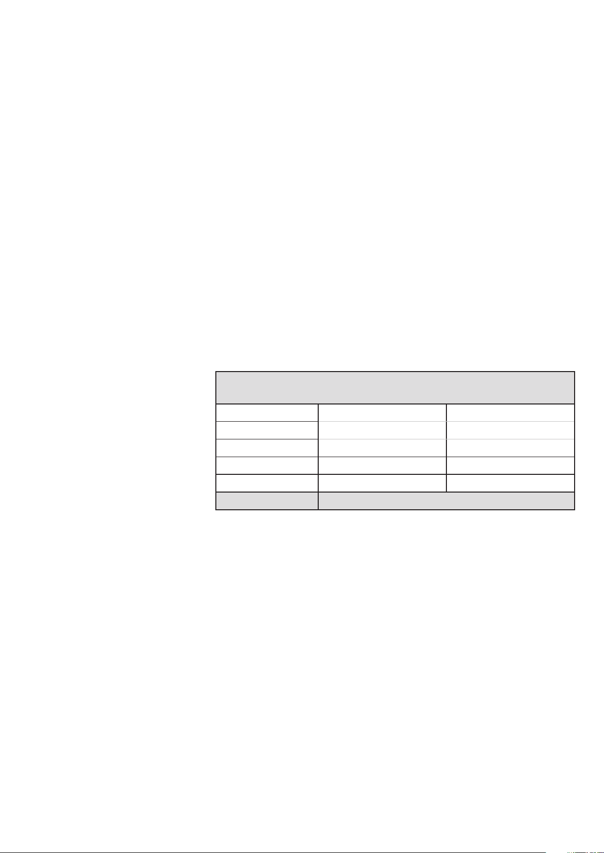
2.4.3 Radio interference suppression of dimmable luminaires
The use of dimmable ECG is only approved in luminaires of protection
class I (PC I) as only here is adequate grounding assured.
Note:
When dimming, the operating frequency of the lamp and the lamp
burning voltage increases at the same time which can lead to elevated
leakage currents. Leakage currents emerging from the lamp always
flow back into the ECG because the current circuit must be closed. To
keep cable-related interference as low as possible, the leakage current is offered a different return path, the ground conductor (=casing)
and the PE connection of the ECG.
In brief: Dimming is not possible without grounding. Dimmable ECGs
only function in PC I luminaires and not in PC II luminaires as these
have no protection contact. Connecting the dimmable ECG to the
functional ground is not permissible.
L N
L N
Radio interference suppression with PC I
R
R
Lamp
Grounded metal plate or reflector
ECG
PE
Figure 5: Protection class I luminaires
The maximum 50 Hz leakage current of the ECG via the ground fault
circuit interrupter (FI switch) is 0.5 mA.
• Mains cables and control lines may be routed together and should
be laid close to the luminaire wall
•
Mains and control cables must not be laid close to the lamp cables
• If crossovers of mains and lamp cables are unavoidable, they
should cross perpendicularly
• Do not lay the PE conductor together with the lamp cables
• Do not use shielded lamp cables (reduction of capacity leakage
currents)
• The OSRAM DALI/DIM ECG must always be installed near the
lamp(s) so that the lamp cables can be kept short in the interests of
good radio interference protection
14
Page 16
Notes:
•
•
• Max. lamp cable length of the "hot end" (higher potential to
ground): T5, T8: 1 m/T4: 0.5 m
• Excessively long lamp cables cause the following problems:
- Poor radio interference suppression
- Uncertain lamp detection (not in T8)
- Poor synchronization of 2-lamp OSRAM DALI/DIM ECGs
• Lay the lamp cables close together and close to the lamp
• Lamp cables must not be laid in metal pipes and must not be
shielded cables
• Guide the cables of the different lamp ends separately
• In the case of multi-lamp OSRAM DALI/DIM ECGs, the cables to
the respective lamp ends must be of the same length to prevent
differences in the brightness
• When dimming florescent lamps the maximum lamp voltage is
reached at the lowest dimmer setting (3 %-10 %) due to the negative current-voltage characteristic
Maximum line lengths between dimmable ECG
(QTi DALI/DIM) and lamps
Cold ends* Hot ends*
1-lamp 21, 22 1-lamp 26, 27
2-lamp 21, 22, 23 2-lamp 24, 25, 26, 27
T5
T8
1.5 m 1.0 m
1.5 m (2 m HF DIM) 1.0 m (1.5 m HF DIM)
DULUX D/E, T/E Every 0.5 m
Table 2: Maximum cable lengths between dimmable ECGs and
lamps
* "Hot ends" are the lamp cables that have the highest potential to the
switching ground or protective ground. The other "cold ends" of the
lamp cables have a lower potential to ground.
Note:
• Maximum capacitance of a filament cable pair to ground:
T5: 75 pF
T8/DL: 150 pF
• Maximum capacitance between "hot" and "cold":
T5: 15 pF
T8: 30 pF
15
Page 17

2.4.4 Operation of multiple ECGs in a luminaire
If several dimmable ECGs are operated in a luminaire, there can be
interference effects and hence to flickering, jerky dimming or even to
shutdown of the ECGs if they have not been correctly installed. The
cause for this are inductions between the lamp current circuits of several ECGs: If a lamp running at 100 % transfers just 1 % of its current
into the neighboring lamp dimmed to 1 %, this represents a fault of
100 %. The same applies to coupling between a heating current circuit, i.e. feed and return lines to one side of the lamp and the neighboring lamp circuit.
There should, therefore, be a minimum spacing of 12 cm between the
lamp circuits (lamp and cables) of different ECGs. If this is not possible, the lamp wiring must be carefully installed so coupling between
the lamp circuits is reduced to a minimum:
• Lay the lamp cables close to the appropriate lamps so that the
area covered by the lamp circuit is as small as possible. The lamp
circuits of the two ECGs must not overlap. This is particularly important for color control if adjacent ECGs are dimmed to different
levels.
• There should be a spacing of several centimeters between the
lamp cables of two ECGs
• The "short" (hot) lamp cables (see also ECG imprint) should lead to
one side of the lamp and should be as short as possible. The "long“
(cold) lamp cables to the other side of the lamp (see Table 2)
• Mains and control cables should not be laid close to the lamp ca-
bles (prevents undesired couplings into the control cable)
• All the mains and control cables may be routed together. To ensure
that radio interference suppression is not impaired, there should be
a gap of several centimeters to the lamp cables.
16
Page 18
The better these recommendations are implemented, the more stable
is the light at the lowest dimmer setting, even with a very small lamp
spacing – and, hence, the full temperature range of the ECGs can be
used.
• In the "worst case" twist the cables of the heating circuits together,
hence ensuring they lie close together. With 1-lamp ECGs these
are the 21-22 and 26-27 cables, with 2-lamp ECGs; 21-22 and
21-23, 24-25 and 26-27. This is particularly important if adjacent
ECGs are operated at the lowest dimmer setting (1(3)%).
If there still are problems: Remove all lamps except for the most
"problematic" ECG – this will eliminate possible faults from the other
lamps. If the lamp then works correctly over the entire dimming range,
the decoupling measures for the other lamps (cables) are still not adequate.
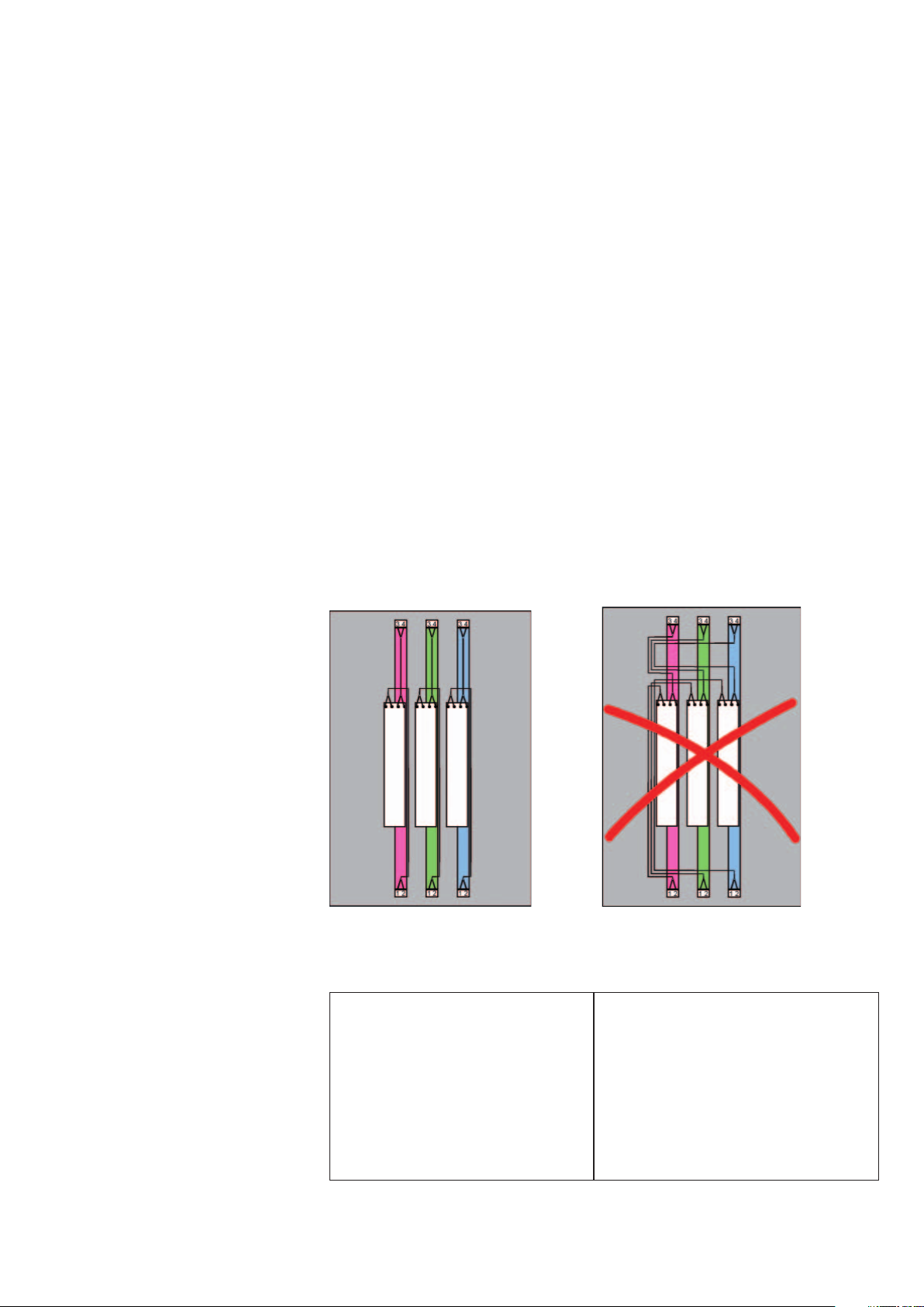
2.4.5 Wiring examples of dimmable electronic control gear
Figure 6: Three 1-lamp ECGs
Correct: Wrong:
The lamp lines are laid close to
the respective lamps.
There are no overlapping lamp
current circuits. The “hot" side
is up and the “cold" is down.
17
The lamp lines of all ECGs are laid
together, also overlapping lamp
current circuits are formed in this
way.
Page 19
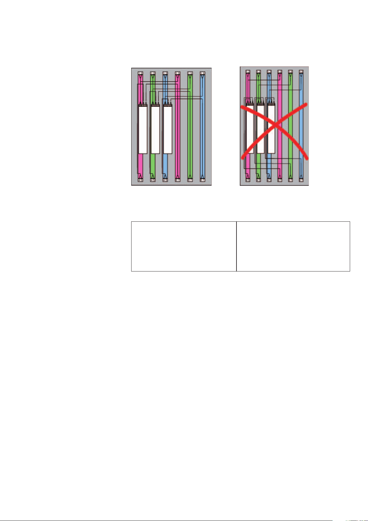
Figure 7: Three 2-lamp ECGs
Correct: Wrong:
The lamp lines are laid close
to the respective lamps. The
overlapping of the three right
lamp current circuits is minimized.
Note:
T5 florescent lamps must be used so that the lamp stamps are on
the same side. The lamp stamp must be underneath (Cold Spot) in
the upright burning position. If this is not the case, the lamp parameters will fluctuate which can lead to unstable burning behavior of the
lamp.
2.5 The DALI interface – technical details
DALI defines the digital communication between a control unit with
DALI interface and a DALI controller (ECG). The detailed specifications
of the DALI interface can be found in IEC 62386.
The lamp lines of all ECGs are laid
together, also overlapping lamp
current circuits are formed in this
way.
2.5.1 The DALI system principle
Each control unit works as a "master" and controls communication on
the control cable. ECGs, in contrast, may only respond as a "slave" to
a request of the "master".
DALI relies on consistent intelligence distributed throughout the
system, an intelligent control unit communicates with intelligent components. For example, the control unit only issues the command:
"Scene 1" and the processor in the ECG adopts the desired light
value. This way all ECGs achieve the set value at the same time.
18
Page 20

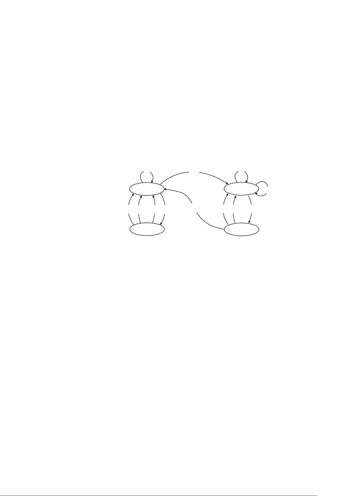
2.5.2 DALI topology
•
•
•
The DALI ECGs are wired in parallel to each other and groups are not
taken into consideration. Star configurations are also possible. Ring
wiring is not permitted (indicated by X in the diagram). There is also no
need for terminating resistors on the communication cable.
Figure 8: DALI topology
2.5.3 DALI parameters in the ECG
The following data can be stored in the DALI ECGs when a DALI
system is started up:
• Group assignment of the DALI ECG (max. 16 groups, multiple
assignment is possible)
• Individual address for accessing each ECG directly (max. 64)
• Lighting values for the individual scenes (max. 16)
• ECG parameters that determine the behavior of the ECG:
• Dimming rate
•
• Behavior when the mains voltage is restored (Power On Level)
Behavior if the voltage fails on the interface (System Failure Level)
In addition to the above-mentioned options, it is always possible to
address all the devices together, even without programming the devices beforehand (construction site function).
19
Page 21
2.5.4 Requirements to be met by the transmission cable
When selecting a cable make sure that the voltage drop on the line
does not exceed 2 V at 250 mA. As with 1…10 V systems, the power
supply and control line can be run in the same cable. This means, for
example, a 5-core NYM cable can be used to connect the DALI ECG
without any problems. The maximum permitted total length of cable
between the controller and the connected ECG is 300 m.
Cross section of the power cable:
A = L x I x 0.018
A = Line cross section in mm², L = Cable length in meters,
I = Max. current of the supply voltage in A,
0.018 = Specific resistance of copper
The following formula is used as a basis for finding the cable cross
section (transmission and power cable):
Line length
Line cross section
up to 100 m 100 to 150 m 150 to 300 m
0.5 mm
2
0.75 mm
2
1.5 mm
2
Note:
Because of the different technical properties of the DALI interface in
control units found on the market and the differing local conditions of
the installation, it is recommended to limit the overall line lengths used
in the system to 300 m.
2.5.5 Wiring diagram for DALI ECGs
For reasons of clarity it is recommended to use the black and the gray
cable for DALI.
Neutral conductor
e.g.
Protective earth
Figure 9: Wiring diagram for DALI controllers
20
Page 22
Controllers and electronic control gears may be connected to different
power supply phases.
L3
L2
L1
N
PE
LNPE DADA
DALI
controller
~
~
ECG Quicktronic DALI
DA
DA
~
~
ECG Quicktronic DALI
DA
DA
1
2
3
4
1
2
3
4
Lamp
Lamp
~
~
ECG Quicktronic DALI
DA
DA
L1NPEDA L2 L3DA
Figure 10: Wiring diagram for DALI controllers
1
2
3
4
Lamp
21
Page 23

2.6 DALI data transfer
Undefined
Undefined
"Low Level"
receiver range
22.5 V max.
9.5 V min.
20.5 V max.
11.5 V min.
16 V typ.
0 V typ.
Receiver unitSender unit
6.5 V max.
-6.5 V min.
4.5 V max.
-4.5 V min.
8 V typ.
Undefined
“High Level"
sender range
“Low Level"
sender range
“High Level"
receiver range
With DALI, data telegrams are produced by short-circuiting and re-
leasing the line in order to generate the corresponding "low" or "high"
logic states. This may be caused by either the ECG or by the controller. In the event of a short-circuit the current is limited by the interface
supply to 250 mA. In the idle state (no data transfer) approx. 16 V
on the ECG. The following figures illustrate data transfer via DALI:
DC
is
Figure 11: Voltage level on the DALI interface
22
Page 24
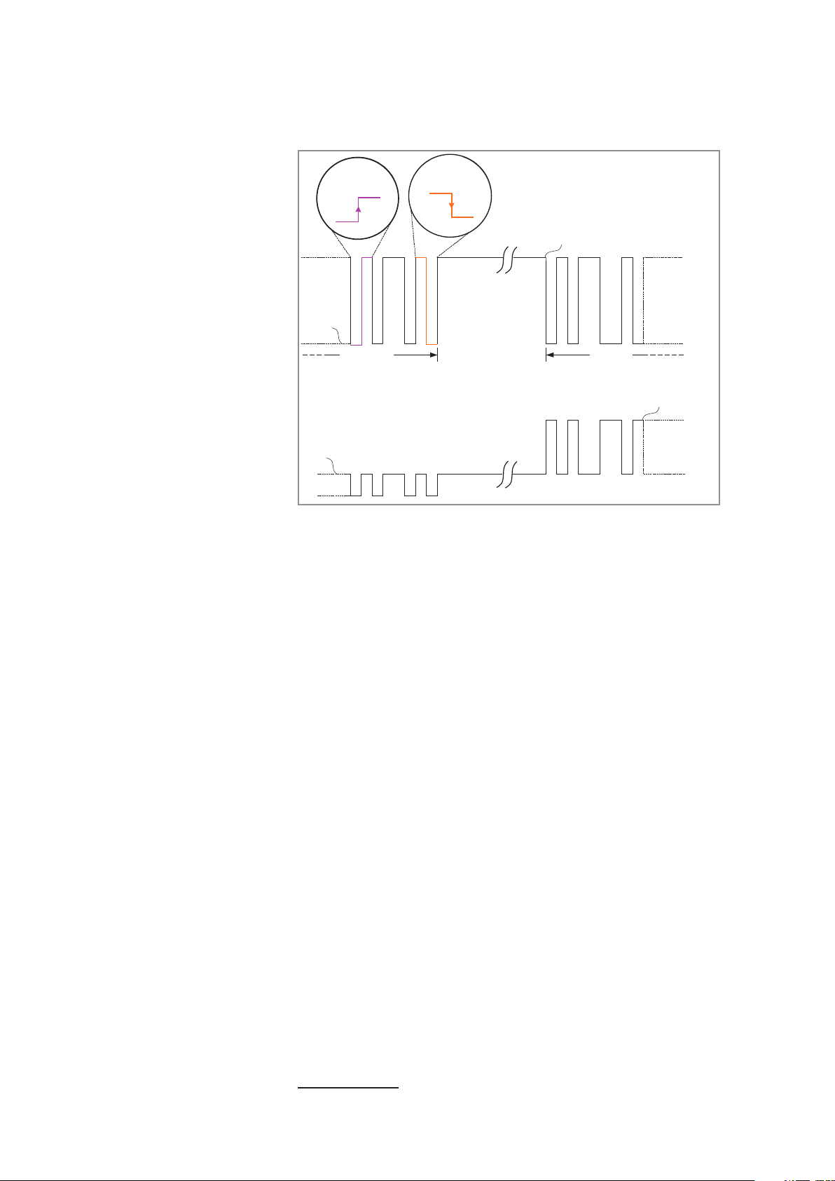
Vol tag e
Low level
“Biphase" databit
coded with value “1"
“Biphase" databit
coded with value “0"
High level (= idle state)
Incoming data
telegram
Current consumption < 2 mA
Current
ECG response
Current consumption
< 250 mA (active limit
by the DALI supply)
Figure 12: Data transfer using the Manchester code on the DALI line
Data is transferred using the Manchester code. The signal edges in
the middle of the bit carry the information here. A trailing edge indicates a logical zero and a rising edge a logical one.
2.6.1 Behavior in the event of a fault
If there is no power at the DALI interface (controller faulty or switched
off), the System Failure Level is set. The Power On Level is activated
after a mains voltage failure (230 V). The System Failure Level has the
higher priority.
Both values are set at the factory to 100 % luminous flux, but can
be individually programmed with the Dali Luminaire Tool (DLT) from
OSRAM, for example.
2.7 The DALI dimming curve
IEC 62386 defines the dimming range of a DALI controller from 0.1 to
100 %. The dimming curve is shown in the graphic below. As far as
the eye is concerned, this categorization is a linear response
5
accord-
ing to the Weber-Fechner Law.
5
The Weber-Fechner law states that the subjective strength of sensory stimuli is
logarithmically related to the objective intensity of the physical stimulus.
23
Page 25
The dependency of the relative luminous flux X (n) on the digital 8-bit
.%8 ,2
)(
)1()(
Const
nX
nXnX
==
+−
value n is described by the following correlation:
−=n
1
253
3
10)(
nX
!
This results in the following graphical association:
Figure 13: DALI dimming curve
2.7.1 Brief overview of the most important dimming values
0 0,1 0,5 1,0 3 5 10 20
0 1 60 85 126 144 170 195
30 40 50 60 70 80 90 100
210 220 229 235 241 246 250 254
percentage luminous flux
digital dimming value
percentage luminous flux
digital dimming value
Table 3: Values of digital dimming value against percentage luminous
flux
As not all DALI controllers start at 0.1 % luminous flux, the smallest
value for DALI ECG is 85 for example (corresponds to 1 % luminous
flux). All values below 85 (except for 0 = off) are interpreted as the
minimum light level. To ensure that the transitions from one digital level
to the next are not visible, DALI ECGs from OSRAM feature digital
“smoothing" (this is an additional function of the QTi for increasing
lighting comfort and is not part of the DALI standard).
24
Page 26

2.8 Features of the digital interface
• IEC 62386 – This allows the combination of units from different
manufacturers. A special feature to be noted is that the DALI man-
ufacturers represented in the AG DALI.
6
test their units together in
order to guarantee high functional security.
• Physical usable data rate of 1200 bit/s enables fault-free opera-
7
tion
• Safe interference voltage gap – the generously dimensioned inter-
ference voltage gap of the high and low level guarantee safe operation
• Data coding – the Manchester code is used; its structure allows
detection of transmission errors
• Maximum system current – the maximum current that a central in-
terface
8
supply must deliver is 250 mA. Each control unit may take
max. 2 mA. This must be taken into consideration when selecting
the interface supply.
• Limited system size – a maximum of 64 control units with an in-
dividual address can be operated differently in a single system
• Feedback of information – ON/OFF, current brightness value of the
connected lamps, lamp status etc. are possible
• Two-wire control line – there should be two basic insulations be-
tween two conductors. Hence, single-layer insulation of a conductor is adequate. Control and supply lines can be laid together; a
minimum cross section of the line must be maintained here. The
maximum line length between two connected system subscribers
must not exceed 300 meters
• Potential-free control input – the control input is electrically sepa-
rated from the mains supply. The ECGs can thus be operated on
different outer conductors (phases)
• No terminating resistors required – the interface lines do not need
to be connected to resistors
The DALI interface of the control unit also supplies the DALI interface of the
6
Every ECG manufacturer that has the DALI logo on its ECG is a member of the
AG DALI
7
40 commands/s and 16 bits ! 640 bit/s
8
DALI interface on the control unit:
connected DALI components. To ensure that the total current of max. 250 mA
permitted for DALI is not exceeded, no other DALI supplies or DALI controllers
can be connected to this system. In order not to exceed the max. permissible
voltage drop of 2 V on the interface lines, the line cross section must be chosen
according to the table in the technical details (2.5.4).
25
Page 27

• Dimming range 1 %…100 % (the lower limit depends on the lamp
and manufacturer). The progression of the characteristic is standardized and adapted to the sensitivity of the eye (logarithmic
characteristic). Because of the standardization, a similar sense of
brightness is achieved when using control units from different manufacturers
• Programmable dimming times – special settings such as light
change speeds (e.g. from 1 % to 100 % dimmer setting) are possible
• Disconnection of the data line – the specified light values are ad-
opted automatically
• Storage of light scenes (different group-dependent dimming states)
– up to 16 scenes can be stored
• Connection via converter to building management systems – the
interface is primarily conceived for room applications; it can be integrated into building management systems via gateways
• Simple system reconfiguration – once the system is set up and
configured, changes of the system function, the light scene and
light functions are only a matter of configuration and do not require
any changes to the hardware. Example: Regrouping of luminaires
in a large office building
• Simple integration of new components – if an existing illumination
system is to be extended, new components can be added anywhere within the system. Attention must be paid here to adequate
dimensioning of the system supply
• Polarity freedom of the interface
2.9 Characteristics of the 1…10 V interface
Note:
This chapter is based on OSRAM ECGs types QTi DIM and HF DIM,
abbreviated to OSRAM DIM ECGs in the following
• Control is carried out via a fail-safe DC signal of 10 V (maximum
brightness; control line open) to 1 V (minimum brightness; control
line shorted)
• The control power is generated by the ECG (max. current: 0.6 mA
per ECG)
• The voltage on the control line is voltage-insulated from the mains
line (basic insulation), but there is no safety extra-low voltage
(SELV)
• ECGs in different phases can be dimmed by the same controller
26
Page 28

Note:
•
•
Due to the characteristics of the 1…10 V interface, the following must
be noted:
• All control lines of an ECG installation must be connected with the
right polarity (+/-)
• The control line is voltage-insulated from the mains line but there is
no safety extra-low voltage (SELV). Therefore, cables and terminals
that are approved for supply voltage 230V must be used for the
installation
• The control voltage is simple to limit upwards or downwards with
resistors; several control units can be combined with one another
• The correct function of the ECG can be tested as follows:
• Switch-on of the ECG with open control line. The lamp must
ignite and burn with max. luminous flux
• Switch-on of the ECG with shorted control line (wire jumper).
The lamp must burn with min. luminous flux
• Each OSRAM DIM ECG can be used as a normally non-dimmable
ECG if there is no control unit connected to the control line
• The dimmable ECGs are only dimmed via the 1…10 V interface
and switched via the mains line
• The maximum load capacity of the control unit (switched output
and 1…10 V output) must be heeded
• The connected control unit must always be able to handle the cur-
rent supplied in the control line by the ECG (current sink) and to
reduce the control voltage. This precept is fulfilled by accordingly dimensioned potentiometers as well as by all OSRAM control
components. Normal power supplies, converter boards etc. do not
necessarily have this characteristic! To check, connect the control
unit, set to the lowest brightness and measure the voltage on the
control line. The set value is 1V or less
• OSRAM DIM ECGs cannot be dimmed via the mains line (e.g. with
phase control mode, round control pulses etc.)
27
Page 29
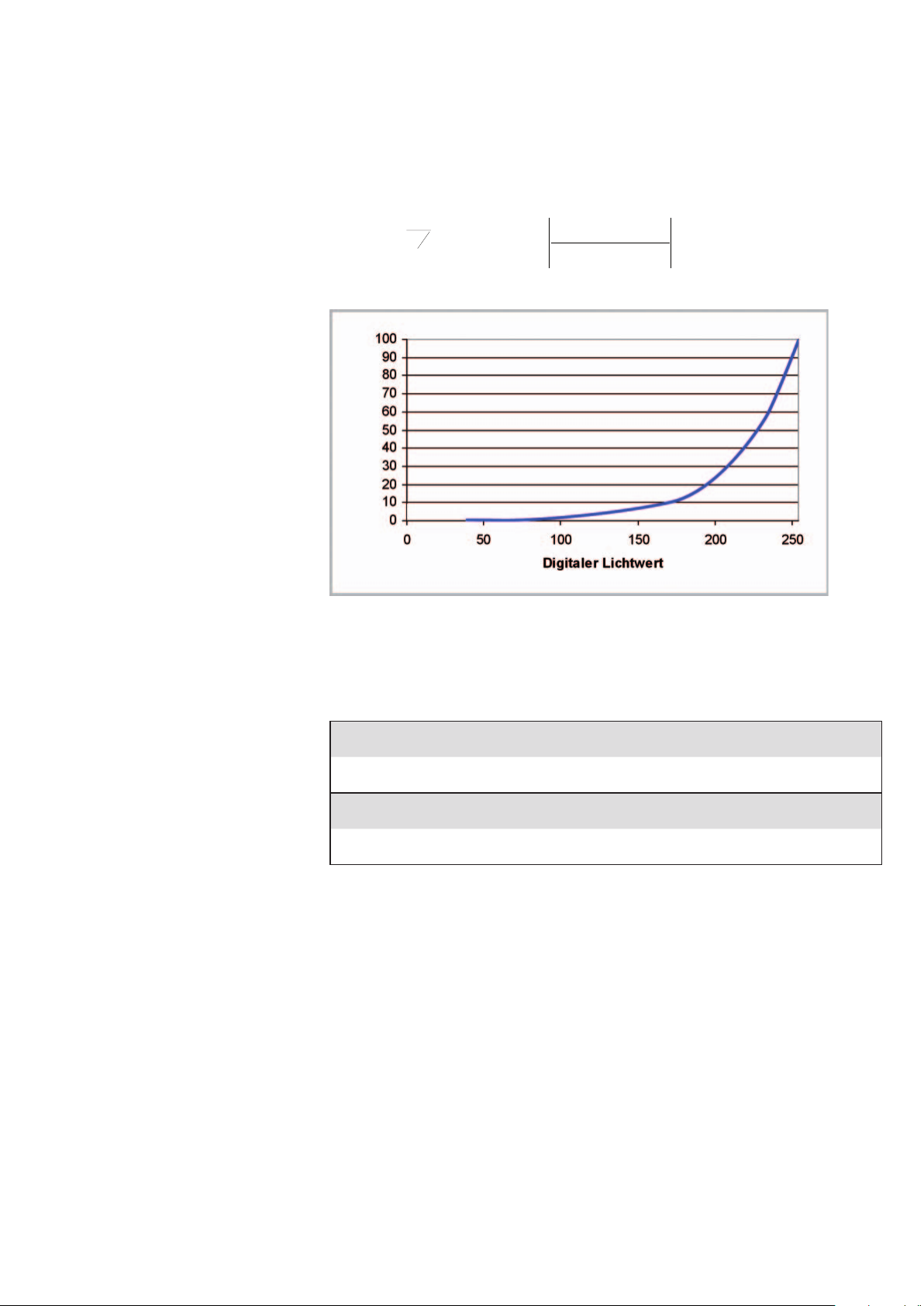
2.9.1 The 1…10 V dimming curve
The 1…10 V interface is defined in IEC 60929. In the control voltage
range of 3 V
tive luminous flux. In the 1…10 V interface, a logarithmic response
(like the DALI units) is adjusted by a logarithmic potentiometer.
Figure 14: The 1…10 V characteristic: Luminous flux against control
voltage
to 10 V there is a largely linear relationship to the rela-
luminous flux in %
Control voltage in V
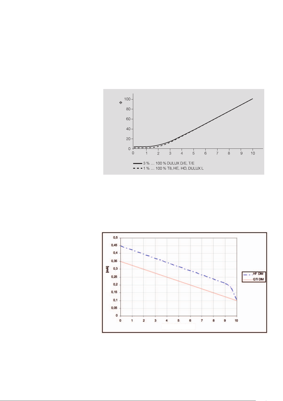
The control current in the 1…10 V interface drops with increasing
control voltage. Unlike the DALI interface, this does not therefore remain constant.
Control current
Control voltage [V]
Figure 15: Decreasing control current with increasing control voltage
28
Page 30

3 Additional characteristics of
•
•
•
dimmable electronic control
gears from OSRAM
9
3.1 OSRAM DALI/1…10 V ECG: Added-value through intelligent features
• Automatic lamp detection through intelligent multi-lamp operation
(reduction of the ECG type variety)
Lamps of the same length and different powers can be operated
on an ECG. Furthermore, there are special approvals for specific
ECG lamp combinations
10
• Dimming range to 1 % of the rated luminous flux (3 % in CFL)
• Ignition of the lamp at an ambient temperature of -25 °C
• Optimized lamp warm start within 0.6 s [including HF DIM]
• Temperature-dependent “cut-off” at dimmer settings > 80 %
Shutdown of the filament heating at dimmer settings > 80 % pre-
vents a permanent heating current through the lamp electrodes
during operation. This reduces the filament loading and the power
loss by approx. 2W
• Power reduction by the ECG at excessively high ambient tempera-
tures in order to protect the electronics ! Can be used in very
close, hot luminaires (operating life, increased light yield, simplified
safety approval)
• High T
temperatures (T
point values (Tc < 80 °C) enable operation at high ambient
c
values)
a
• Stable dimming operation also in amalgam lamps (CFL (IN) and
OSRAM T5 CONSTANT lamps) ! particularly suitable for use in
areas with low ambient temperatures (e.g. cool rooms, outdoors):
relative luminous flux > 90 % from 0 °C to 70 °C
• Intelligent power control upon detecting instabilities in the lamp circuit (amalgam lamp start) – protects lamp/ECG
• Permanent Heat Mode (PHM) for lighting effects (permanent fila-
ment heating, switch-on of the continuous lamp pre-heating by
digital command, not DALI standard): The PHM ensures that, at
a light value = 0 (switched off lamp(s)), the lamp electrodes are already heated. A delay-free lamp start is therefore possible
• > 1 s on/off switching cycle in the PHM ! No restrictions
• 0.5 s < t < 1 s on/off switching cycle in the PHM ! 30 k
switching actions with T5, 100k switching actions with T8
• < 0.5 s on/off switching cycle in the PHM ! 15 k switching
actions with T5, 50k switching actions with T8
• Optimized filament heating and lamp operation at mains undervoltage (no damage to the lamps)
9
Applies to OSRAM QUICKTRONIC Intelligent (QTi) DALI/DIM ECGs, exceptions
given in […]
10
Special releases for QTi DALI/DIM and HF DIM types of the ECG lamp
29
Page 31

• EoL shutdown after Test 2
Asymmetric power test for detecting defective lamp electrodes or
high-impedance lamp paths due to leaks in the glass tube
• Chip ID (CIN = Chip Identification Number, serial number) for simple system installation ! OSRAM DALI Luminaire Tool (DLT): Address assignment via CIN possible
• EEPROM for backing up settings/parameters even if the mains
supply fails
• Lamp replacement without mains reset (automatic lamp reactivation after lamp replacement) [including HF DIM]
• DC operation in the input voltage range of 154-276V/lamp start
above 198V [including HF DIM]
• Optimized radio interference suppression: Maintaining the requisite
EMC thresholds with a comfortable safety margin for ease of luminaire installation [including HF DIM]
• DALI standard acc. to IEC 62386 -101/-102/-201
• 1…10 V standard acc. to IEC 60929
3.2 OSRAM DALI ECGs and TouchDIM interface
To realize light controllers as economically as possible, the DALI ECGs
from OSRAM also have the integrated TouchDIM function
11
. It is there-
fore possible to dim and switch DALI ECGs directly with mains voltage on the DALI control terminals (TouchDIM Interface = TDI). Only
one commercially available switch is required, the ECG assumes the
control function.
The changeover between both operating modes – TouchDIM or
DALI operation – can only be realized after mains voltage. Hence, it is
not possible to switch between the operating modes via an integrated
safety mechanism during operation. Switching between both operating modes can take place as often as necessary. TouchDIM must
never be used at the same time with a DALI control system.
TouchDIM offens all the functions of a comfort dimmer:
• Soft starting of the lamp (lamp starting at the lowest dimmer setting
(1 % (3 %), lowest luminous flux)
• Short press: On/Off
• Long press: Dimming
• Memory function (light value stored by double-clicking)
• All settings are remained even after a power outage
11
TouchDim is not part of the DALI standard
30
Page 32
3.2.1 Wiring and line compensation
• The line lengths between buttons and the farthest away DALI ECG
should not be longer than 25 meters. Where line lengths over
25 meters are required, compensation methods (bell transformer,
resistor) must be used
• Do not use more than 6 DALI ECGs in one TouchDIM appli-
cation (up to 6 ECG can be controlled by one switch, the number
of operating points is limited to 2)
• Different lamp families should not be mixed because of the
different preheating times (e.g. HO lamps (500 ms starting time) vs.
HE lamps (700 ms starting time)
• If more than one operating point is required, a maximum of 2 buttons per TouchDIM application can be switched in parallel
• The TouchDIM wiring must be rated for mains voltage (230 V)
L 3
L 2
L 1
N
P E
~
~
DALI ECG
D A
DALI ECG with TouchDim
D A
function
1
2
3
4
L a m p
1
2
3
4
1
2
3
4
L a m p
L a m p
Control button
~
~
DALI ECG
DALI ECG with TouchDim
D A
function
D A
~
DALI ECG
~
DALI ECG with TouchDim
D A
function
D A
L 2 L 3
L 1 N P E T
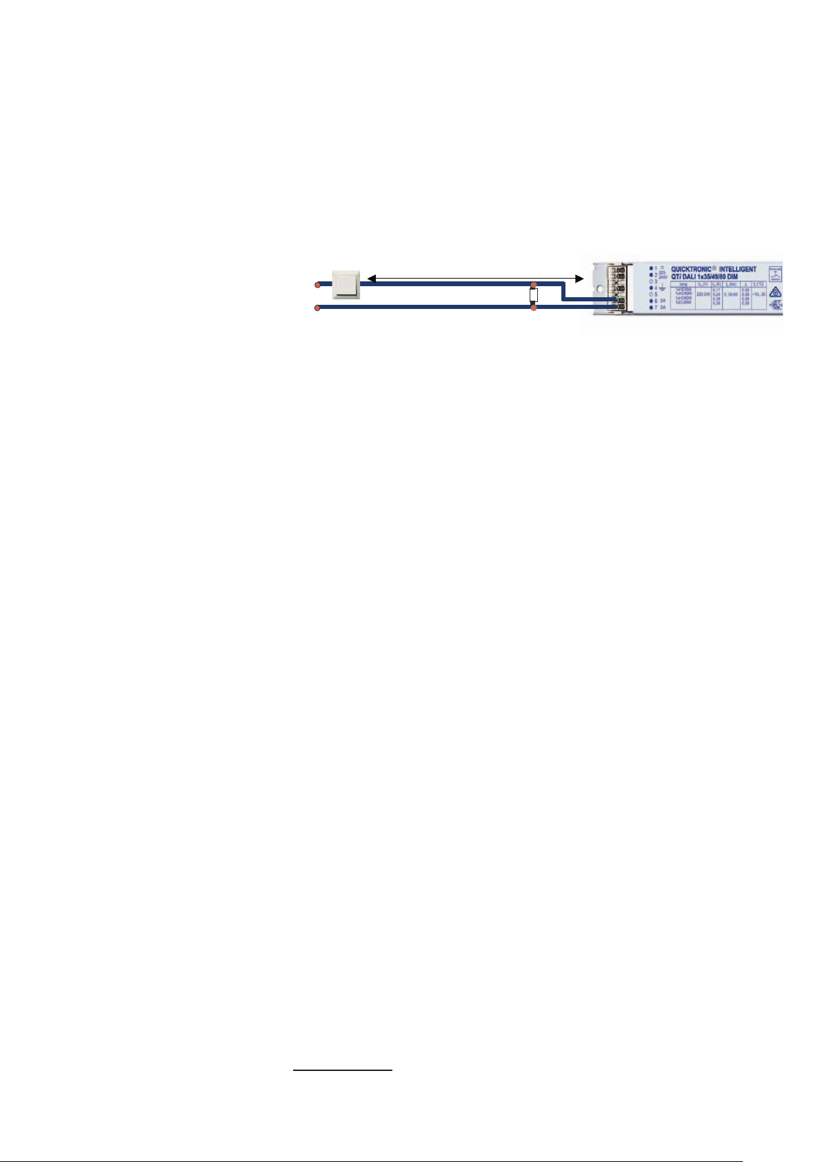
Figure 16: Operation via buttons. Another button can be connected
in parallel to the first one. Up to 6 ECGs can be controlled by one
switch, the number of operating points is limited to 2.
31
Page 33
Note:
• Only use switches without control lamp and with 230 V normallyclosed contact as the permanent current through the glow lamp
can lead to malfunctions
• TouchDIM is not part of the DALI standard (IEC 62386), but rather
an additional OSRAM function
3.2.2 Operating parameters for TouchDIM
To operate the TouchDIM, AC voltages of 10…230 V (RMS) at
a frequency of 46…66 Hz can be used – there is no DC voltage
allowed.
3.2.3 Compensation of interferences
A control transformer which complies to the following figures and val-
ues must be used with a total line length from the switch to the ECG of
25 m to 100 m in order to prevent interference (e.g. through capacitive
induction):
Primary 230 V/Secondary 12 V, transformer rating required: 25 mW
per connected ECG (i.e. 150 mW with 6 ECGs 2 mA control current
per ECG)
L
N
PE
Button
Installation line
12 V Transformer
Min. power: 25 mW x no. of ECGs
~
~
DALI ECG
DA
DA
Figure 17: Control transformer for compensation close to the ECG
(e. g. in a luminaire)
L
N
PE
Button
12 V Transformer
Min. power: 25 mW x no. of ECGs
Installation line
~
~
DA
DA
DALI ECG
Figure 18: Control transformer close to the switch (e.g. in the subdis-
tributor or in a flush-mounted socket)
32
Page 34
The option of connecting a conventional resistor is also available
(150 kΩ, 1 W) for compensating interferences (damping of the line)
between the phase and neutral conductor. The resistor can also remain in the control line during DALI operation which is not affected
(< 2 mW power loss).
L
Max. 50 m total line length for compensation
of the connection cable
N
R: 150kOhm, 1W
Figure 19: Compensation of the connection line by a resistor (150 kΩ,
12
1 W)
3.2.4 TouchDIM operation
• Switching the lamp on/off: Short button press (< 0.5 s)
• Dimming: Long button press (> 0.5 s), (dimming direction changes
each time the button is pressed)
• Save the reference value in the switched-on condition: "Doubleclick“ (press briefly 2 x within 0.4 s)
• Delete reference value: Double-click with the lamp switched off
(ECG starts with 100 % luminous flux when switched on again)
Note:
Long button press with the lamp switched off: Lamp is switched on at
the minimum dimmer setting and, hence, remains highly dimmed until
the switch is released.
3.2.5 Operating modes with TouchDIM
With the QTi DALI, OSRAM offers two modes for TouchDIM that dif-
fer in switch-on behavior (this refers to the software-controlled switching on/off and not to the switching off of the voltage supply):
Mode 1:
The electronic control gear switches with the last dimming value that
it had before being switched off. The following applies:
Short press: Switching
Long press: Dimming/Switching on at minimum dimmer setting
12
For example: Vishay Beyschlag: MBA/SMA 0204, MBB/SMA 0207, MBE/SMA
0414 - Professional
33
Page 35
Mode 2:
The electronic control gear switches on with the dimming value (pre-
set value) last stored by double-clicking. The following applies:
Short press: Switching
Long press: Dimming/Switching on at minimum dimmer setting
The following figure shows the options of both operating modes to the
user:
Mode 1
LP LP
On
LP DC SPSP
Off
DC
DC
Mode 2
On
LP SP SP
Off
DC
SP = Short Push
LP = Long Push
DC = Double Click
Figure 20: Operating modes and operating combinations by button
34
Page 36

The following table once again explains the behavior of the ECG for
different switching actions:
Action TouchDIM
Short press
(status: switched off)
Short press
(status: switched on)
TDI Mode I: switches on to last value before
switch-off
TDI Mode II: switches on to last double-click
value
Switch-off and store value for next switch-on in
TDI Mode I
Long press
(status: switched off)
Long press
(status: switched on)
Double-click
(status: switched off)
Double-click
(status: switched on
ming in the last 3 s)
Double-click
(status: switched on & no
dimming in the last 3 s)
Power failure
(status switched off)
Power failure
(status switched on)
& dim-
Switch on and fade from min upwards
Dimming as long as button is pressed
Dimming fades upwards or downwards (depending on pending toggle or logic function)
Swap to TDI Mode I ( = auto memory of the
switch-on value), confirmation: switch-on and
dimming to maximum brightness
Swap to TDI Mode II (switch-on value = doubleclick value), confirmation: flashing and dimming
to double-click value
Holiday mode; only in combination with LMS
sensors (see www.osram.com/ecg-lms)
Remains switched off
Switches on to …
TDI Mode I : last value before power outage
TDI Mode II : last value before power outage
Table 4: Behavior of the ECG for different switching actions, TDI =
TouchDIM interface
35
Page 37

3.2.6 Asynchronism/Automation of the system
The increased use of DALI ECGs in button operation shows again and
again that in systems with
• not completely sinusoidal supply voltage (e.g. electronic dimmer on
the same mains supply),
• excessively long line lengths or
• high DALI ECG count (more than 6 ECGs per TouchDIM applica-
tion)
increasing results in asynchronism of the connected DALI ECGs. To
consistently prevent asynchronously running lighting systems in practice, the permissible number of DALI ECGs is limited to 6 units.
3.2.6.1 Prevention/Remedying of asynchronism
With the aid of the DALI repeater that is described in more detail in the
context of the LMS (Light Management Systems) portfolio (see
www.osram.com/ecg-lms), up to 64 ECGs can easily be operated in
the TouchDIM function without having to be concerned about asyn-
chronism. Without the repeater, the TouchDIM application is however
only restricted to floor-standing luminaires or small offices.
3.2.6.2 Synchronization
For physical reasons a TouchDIM can work asynchronously, i.e. the
switching status and dimming direction of the separate luminaires are
different. The following steps help in the synchronization of a Touch-
DIM system:
1st. step: Longpress (> 0.5 s)
! All luminaires switch on
2nd. step: Shortpress (< 0.5 s)
! All luminaires switch off
3rd. step: Longpress (> 0.5 s)
! All luminaires switch on and dim
4th. step: Double-click
! Save dimmer setting (if required)
Note:
TouchDIM was developed for manual control and is not suitable for
After these four steps – long–short–long–double-click – the
again behave synchronously.
automation, e.g. for connecting to a PLC.
ECGs
36
Page 38

3.2.7 Behavior after mains voltage failure
If the luminaire is disconnected from the mains, the ECG saves all
set values. If the light value has been changed before being switched
off, this value is restored, i.e. after a voltage loss, exactly the last
status is reestablished (instant switch-on to the previous present
luminous flux, no "intermediate path" above 100 % luminous flux and
subsequent dimming). All settings (dimming values, lamp on/off,…)
also remain intact with a prolonged mains voltage failure. By doubleclicking, the stored reference value also remains in the ECG after a
power failure and can, if required, be called up again with the luminaire
on/off. If the luminaire was switched off at power failure, it also remains
off when the mains voltage is restored. For this reason, operation in
the TouchDIM mode is not suitable for centrally supplied emergency
lighting applications.
3.3 OSRAM DALI ECGs in emergency lighting applications
Due to the variety of emergency lighting control systems and applica-
tions, this topic cannot be described in detail in this primer.
The integration and testing of the complete emergency lighting sys-
tem acc. to VDE 0108 must always be conducted by the persons responsible for the overall system as the ECG is only one element of the
overall system. The VDE 0108 is a system standard and not an ECG
standard. There are special electronic control units on the market for
local emergency lighting applications with battery integrated in the luminaire. The instructions described here for wiring and programming
the DALI controllers are based exclusively on central battery applications and, hence, on standard DALI controllers (ECGs).
QUICKTRONIC INTELLIGENT DALI ECGs are suitable for emergency
lighting systems based on VDE 0108. All OSRAM DALI controllers detect emergency operation (system failure level) if there is an absence
of voltage on the DALI input (16V DC in normal operation). This function is part of the DALI standard and is supported by all vendors.
37
Page 39

For emergency lighting/voltage loss13 in the DALI controllers two val-
ues can be configured/programmed separately for each unit (e.g. using the OSRAM DALI Luminaire Tool DLT).
• System failure level: Emergency operation (1…100 % light), detected by switching off the control line
• Power on level: Light value after the mains voltage is restored
(1…100 % light)
The system failure level always has priority over the power on level,
especially when switching over (in the event of a brief power outage, emergency operation is therefore ensured). The factory setting
for both values is 100 % light.
Typical data for the QUICKTRONIC INTELLIGENT DALI family impor-
tant for emergency lighting systems are*:
Starting time of the lamp (max.) 0.6 s
Permissible voltage range (DC) 154…276 V
Min. voltage for lamp start (DC) 198 V
Permissible voltage range (AC) 198…264 V
Mains frequency 0, 50…60 Hz
Table 5: OSRAM ECG data for emergency operation of the lighting
system
*Further technical data of the respective ECG type can be found in the
corresponding datasheet or on our homepage at www.osram.com/qti.
The DALI or dimming function of the QTi DALI … DIM is identical in AC
and DC operation.
• During power outages > 200 ms, the ECGs go through the entire preheat-
13
• During power outages < 200 ms, the light stays on (no light failure) because
the ECGs are not preheated again.
ing cycle. The following applies to the QTi DALI/DIM and HF DIM family: The
starting time in HO lamps is 0.5 s and in HE lamps it is 0.7 s. DALI ECGs
require an additional 0.5 s for initialization
38
Page 40
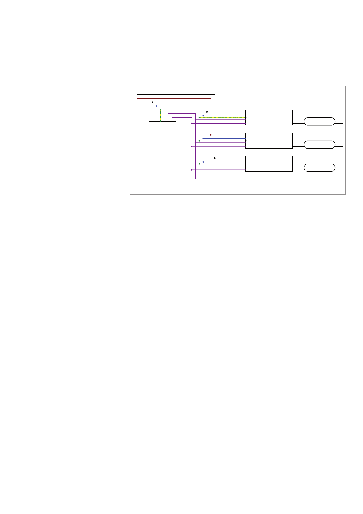
The use of OSRAM DALI electronic control gear in emergency lighting
management is explained in the following.
General UV lighting
L
N
Phase
control
Dimming
button
L
N
controller
IN
IN
DALI
3
D
D
General luminaire lighting
~
OSRAM
~
DALI
DA
ECG
DA
1
2
3
4
4
X
.
Emergency luminaire lighting
~
OSRAM
~
DALI
DA
ECG
DA
1
2
3
4
1
X
.
L
From HV
N
ZB-S
Central battery system
U
U
Monitoring module
0
0
2
D1
D2
D1
max. 1m
D2
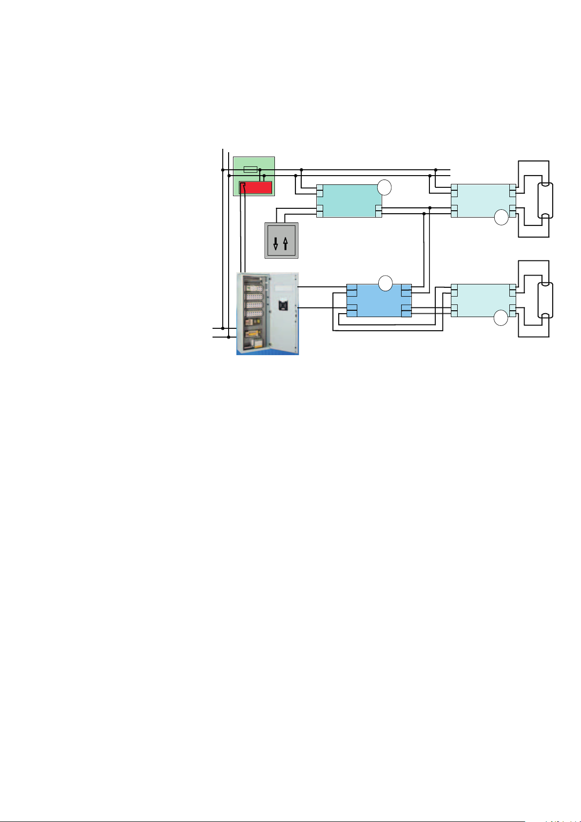
Figure 21: Circuit example of the monitoring module and OSRAM
DALI ECGs in emergency lighting management
The monitoring module (2) enables individual monitoring and control
of the DALI ECGs (1).
The following applies for normal operation:
The OSRAM DALI ECG (1) emergency lighting is supplied with AC
voltage via the central battery system. All electronic control gear can
be dimmed as usual and are controlled by the DALI controller (3).
For maintenance functions (e.g. for servicing, caretaker switching) the
OSRAM DALI ECG (1) emergency lighting can be switched to 100 %
via the monitoring module (2), the commands of the DALI controller (3)
(e.g. dimmer setting) are ignored.
A difference is now made between two cases when switching the
lighting system into emergency operation:
3.3.1 Mains failure at the subdistributor (UV)
In accordance with VDE 0108 when AC mains is present at the central
battery system (CB) in emergency operation, the system must not be
switched to battery but the security luminaires (1) must be switched to
permanent light. The external DALI controller is ignored, the OSRAM
DALI ECG (1) emergency lighting is dimmed to 100 % by the monitoring module (2) using a DALI instruction set.
39
Page 41

3.3.2 Mains failure at the main distributor (HV)
The central battery system (CB) provides DC supply voltage.
ternal DALI controller (3) is ignored, the ECG is dimmed to a previously
defined value
via a DALI instruction set. The emergency lighting level is pre-specified. OSRAM DALI ECGs (1) can communicate DALI and, hence, be
individually dimmed by applying a DC voltage supply.
3.3.4 DC emergency operation of the lighting system without monitoring module
Note:
The "System Failure Level" has priority over the Power On Level, i.e.
The "System Failure Level" can be configured individually for each
The DALI controller (3) is switched off with switchover to the emergency operation of the lighting system. Through
DALI voltage (approx. 16V DC that is always present during normal
operation
lers (4) detect that the "System Failure Level" must be set.
if the DALI voltage is absent when applying the supply voltage to the
ECG, the System Failure Level will be set.
ECG – from 0…100 % light.
by the monitoring module (1), which is DC compatible,
the absence of the
on the terminals of the DALI controllers), the DALI control-
The ex-
3.3.5 QTi DALI: Benefits in emergency lighting applications
• The luminous flux factor can be freely adjusted during battery
• Efficient utilization of the battery capacity through reduced lumi-
• Simple installation in the luminaire
• Use of DALI ECGs as emergency lighting ECGs with unrestricted
3.4 OSRAM DALI LUMINAIRE TOOL (DLT)
• Unrestricted DALI communication to the ECG even in emergency
operation of the lighting system
operation and, hence, matched to the illumination situation
nous flux maintenance
luminance flux reduction also possible without bus
The OSRAM DALI LUMINAIRE TOOL (OSRAM DLT) is a testing and
programming tool for luminaries with DALI controllers. All functions
(except for the individual OSRAM serial number Chip Identification
Number (CIN)) correspond to the DALI standard and are hence vendor-independent.
40
Page 42

The functions of the OSRAM DLT are:
• Luminaire function test (for production)
• Reading of all DALI parameters (e.g. in the event of complaints)
• Preprogramming of all DALI parameters (e.g. for projects)
• Reading and printing of the unique OSRAM operating unit ad-
dress (OSRAM-ID ! CIN (Chip Identification Number)) of each
QUICKTRONIC INTELLIGENT ECG and printing on barcode
(128-bit) for simplified system commissioning
o Placing the label on the luminaire
o Max. 4 ECGs in a luminaire
o Purpose/Advantage
- Simplified installation of a DALI system (no flashing, start-up
from outside)
- No predefined position of the luminaire (position defined with
ID in the luminaire plan)
- System integrator: Assignment of the ID to the position
Figure 22: Reading and printing of the unique OSRAM control unit
address on barcode
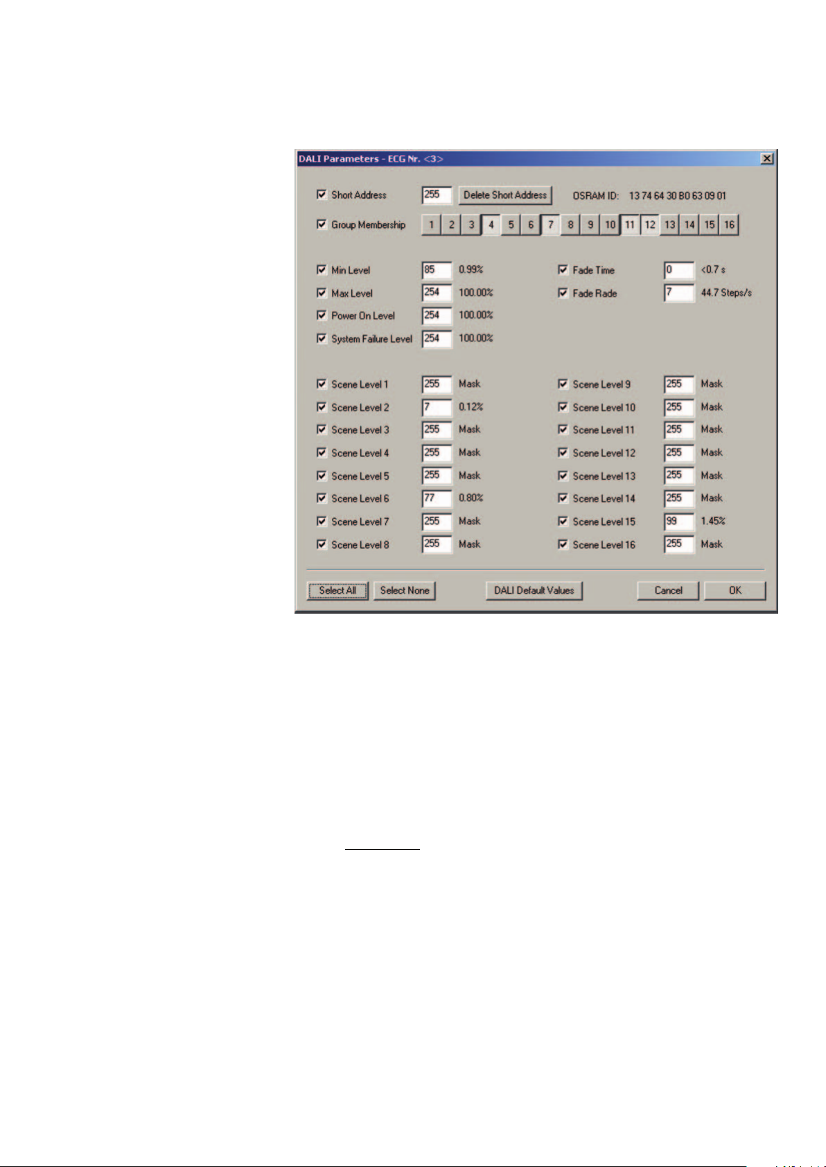
The following section of the software interface shows the DALI param-
eters that can be configured by the DLT. Special attention is drawn
here to the "System Failure Level" and "Power On Level" which come
into play for use in emergency lighting systems:
41
Page 43
n
k
R
Poti
log 100 Ω
=
Figure 23: DALI parameters that can be changed by the DLT
3.5 Basic switching actions of 1…10 V control gear
The simplest type of light control can be realized via an appropriate
logarithmically-dimensioned potentiometer (available from the electrical trade). Because the control power of the OSRAM DIM ECG is
generated by the ECG itself, the resistance value is dependent on the
number n of the connected ECG. It can be calculated according to
the formula:
If the calculated value is not contained in the resistance table, a similar
value should be selected as otherwise full modulation of the lamps is
not possible (this overdimensioning may possibly lead to the fact that
the whole rotation angle of the potentiometer for the brightness control cannot be used). The potentiometer must be designed for at least
a power of P
Potentiometer
= 2.8 mW · n.
A mains switch is also required for switching the lighting system. When
connecting the potentiometer, it is important to note that the full lighting level is reached by turning to the right. When connecting more
than 2 OSRAM DIM ECGs, it is recommended to use a DIM MCU
manual control. Detailed information on this can be found in the relevant documentation (LMS portfolio, see www.osram.com/ecg-lms).
42
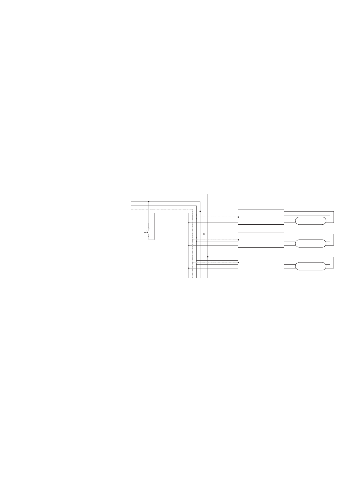
Page 44

The following figure illustrates control via a potentiometer:
N
L
On/Off
switch
Potentiometer
100 kΩ log.
R =
n
n: Number of connected ECGs
N
L
DIMM-ECG
–
+
N
L
DIMM-ECG
–
+
N
L
DIMM-ECG
–
+
–
N
+
L
1
2
3
4
1
2
3
4
1
2
3
4
Lamp
Lamp
Lamp
Figure 24: Potentiometer control of the 1…10 V interface
3.5.1 1…10 V: Staircase operating modes
As a basic principle, frequent switching is not ideal for fluores-
cent lamps and compact fluorescent lamps. Hence, bulbs are
still used in applications with extremely high switching frequency despite the high energy consumption. In staircase operation,
OSRAM DIM ECGs dim the light (1 % luminous flux) when it is not
required. This avoids unnecessary switching operations and saves
energy. Further benefits of the staircase circuit: Because the light is
not completely switched off, a certain amount of light still remains
available as an orientation light. When needed, the full light is im-
mediately present, without having to wait for a preheating period.
Typical applications of the standby circuit are all applications with high
operating cycles, such as staircase, hallway or underground car-
park, especially when the light is controlled with motion detectors or
timer switch.
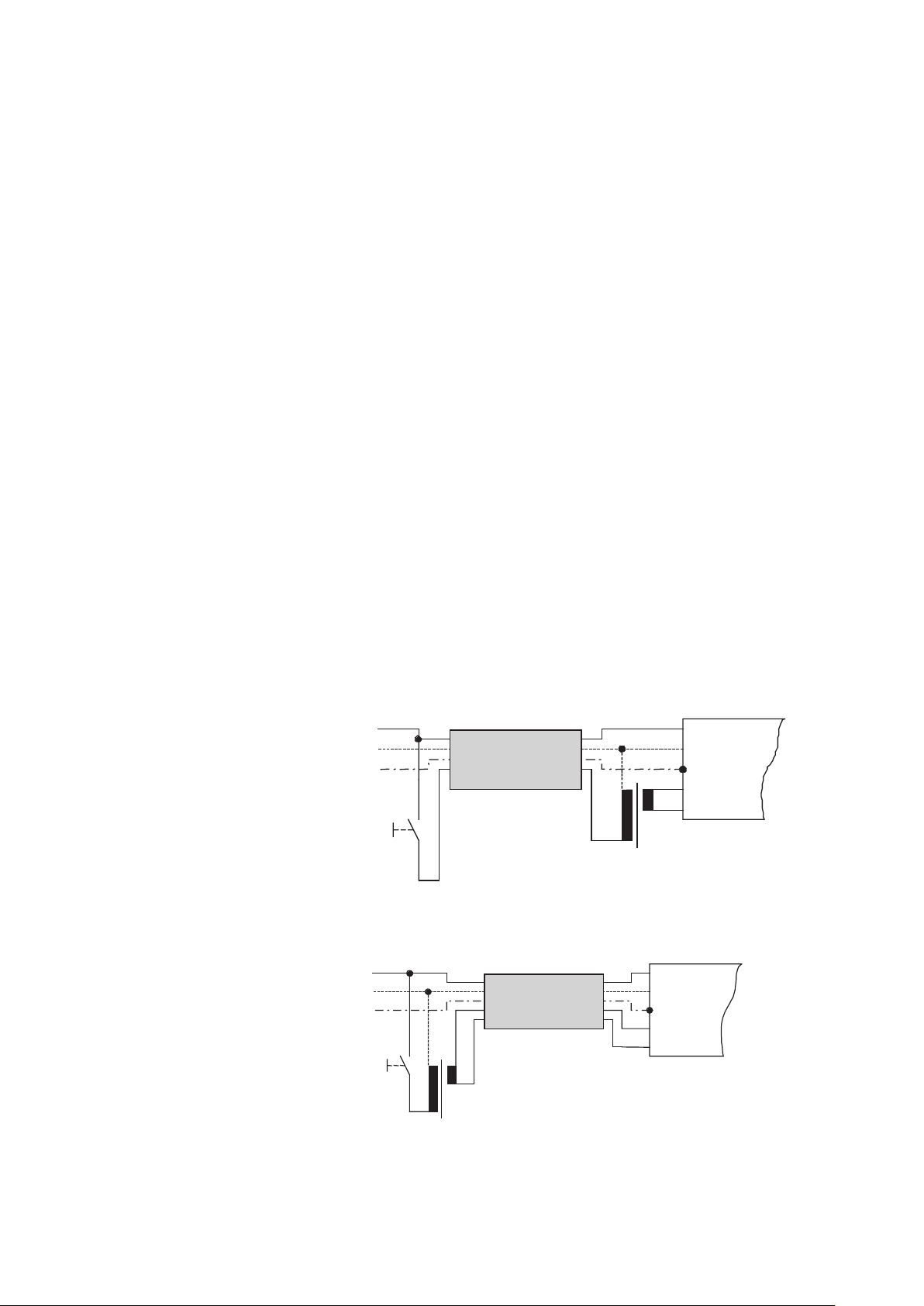
3.5.1.1 Applications
a) Stairwell lighting timer switch
Here a special stairwell lighting timer switch (e.g. Siemens: Type 5TT1
303, see Siemens Catalog) provides the readiness switching of the
OSRAM DIM ECG. Functionality: The stairlight timer switch switches
on the OSRAM DIM ECG at the push of a button (100 % light). After
max. 10 min (time can be adjusted) the light is lowered to a preselected level without intermediate stages. After a total of 30 min it is
switched off entirely. This 30-min cycle can be restarted at any time
by pressing a switch. Thus, the lamp-protecting mode is employed
in the evening hours when the staircase is used more frequently. The
light only switches between the dimmer settings, real switchings are
infrequent. At night, when the stairwell lighting is not required for prolonged periods, the remaining 13 % energy consumption are also still
stored at the lowest dimmer setting.
43
Page 45

Figure 25: Stairwell lighting timer switch
b) Stairwell lighting timer switch and motion detector
Because the button engages the line voltage (L), it can be replaced by
a motion detector. Parallel switching with the switch is also possible.
Because the switch-on time is set on the stairwell lighting time switch,
the switch-on time of the motion detector can be set to a minimum.
Figure 26: Stairwell lighting timer switch and motion detector
44
Page 46

3.5.1.2 Control via analog output
The external control with an analog output 0…10 V (e.g. PC card)
is basically possible. This control module must be capable of taking
the current supplied by the ECG in the control line and of reducing
the control voltage to at least 1 V. For that reason, however, the analog output must fulfill two requirements: It must be potential-free and
may not therefore be connected galvanically with touchable parts or
circuits that are subject to SELV requirements (test voltage 2500 V,
the test voltage to grounded parts is 1500 V). The analog output can
operate as a current sink because it must take the control current of
the OSRAM DIM ECG. Mostly, it is not known whether and how much
current an analog output can take but assistance can always be provided by an interface circuit.
3.5.1.3 Interface circuit
In the case of up to three OSRAM DIM ECGs, it is recommended to
connect the control inputs of the ECG directly with the analog output
(e.g. PC card) and, in the case of four and more OSRAM DIM ECGs,
to interconnect a signal amplifier. Then start up the system, set the
control voltage to 0 V and check with a multimeter directly at the analog output. If the measured value is less than 1 V, the situation is okay
and the system can be started. If the control voltage here is greater
than 1 V, the analog output cannot take enough current and an additional current sink is required in the form of a parallel switched resistor
R. The required value is determined as follows: At a default control
voltage of 0 V, a potentiometer (approx. 5 kΩ linear) is also set on the
analog output and a 1 V control voltage set with it. Disconnect the potentiometer and measure the resistance value (must be greater than
680 Ω), provide and connect corresponding fixed resistor (construction form 0207, power rating 0.25 W, possibly next smaller resistance
value).
+
Analog output,
e.g. PC
–
Figure 27: Control via PC
45
+
DIM SA
R
In
signal
amplifier
–
if necessary
+
Out
–
+
Dimm-ECG
–
Page 47

3.5.1.4 Control via instabus EIB
Dimmable ECG with 1…10 V interface can be easily integrated in
installations with the instabus EIB building control system. The link between EIB and the dimmable lighting system is a switching/dimming
actuator. A switching/dimming actuator is required for each lighting
group. The digital bus signal is converted by the switching/dimming
actuator into the analog 1…10 V control voltage for OSRAM DIM
ECGs. The ECG is switched on/off by an integrated relay contact.
Different functions can be parameterized: on, off, brighter, darker, as
well as a default defined control voltage. Sensors for daylight control
etc. are normally connected at the instabus level. Detailed information
is available from manufacturers of the instabus EIB.
3.6 Special wiring diagrams, tips and tricks
3.6.1 Temperature-dependent control
The recognized temperature problems in dimmed fluorescent lamps
can be resolved by a temperature-dependent lower limit of the dimmer setting.
The latest generation of the QTi DIM (as of the end of 2008) does this
automatically. For older versions, the following implementation applies:
The stability threshold (stable dimming operation at low temperatures
(< 10 °C)) depends greatly on the lamp tolerances. In control types
where the lamp starts at 100 % (e.g. stairwell switching), the temperature limit can be lower. Therefore, in an automatic control both the
response temperature and the control voltage should be adjustable.
The following circuit is recommended:
+
–
Temperature
controller
+
Main control unit
–
1
2
+
Aux. control unit
approx. 4V, e.g. DIM MCU
–
Figure 28: Temperature-dependent control
46
Page 48
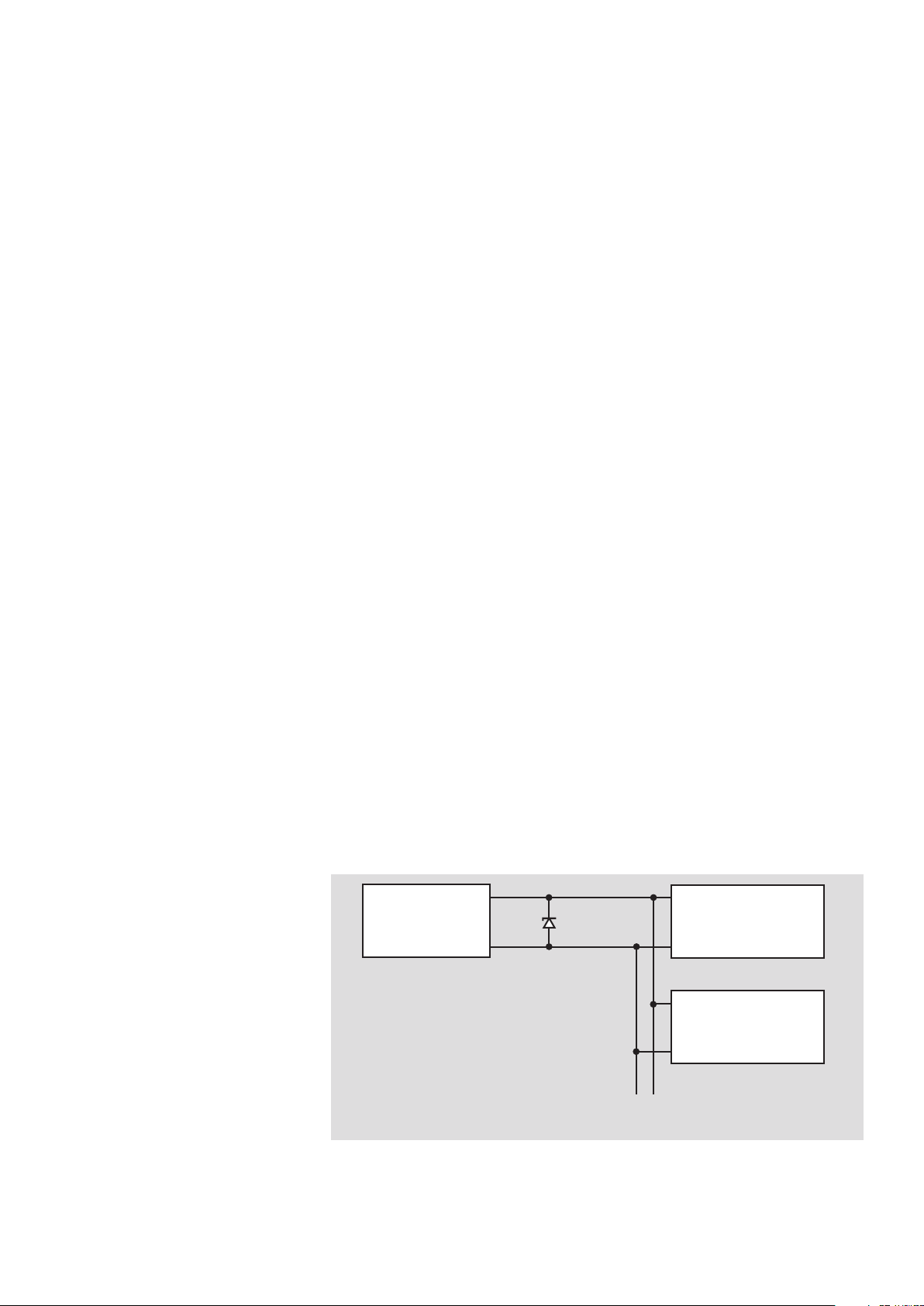
The temperature controller can be a room temperature controller for
heating control, for example. The switching temperature (e.g. 0 °C)
should be as precisely adjustable as possible. The switch must be a
closer, i.e. must be closed at high temperatures. Such appliances are
offered with a bimetal contact (e.g. 2NR9 090-1, power supply not
required) or with a temperature sensor (e.g. 2NR9 078, power supply required). Any existing heating resistors for thermal feedback (RF)
or nighttime temperature reduction (NA) are not connected. The only
power supply line is the possibly required power supply. Depending
on the application, different protection types are necessary. Further
details are available from specialist personnel for heating and air handling units.
3.6.2 Limitation of the control voltage
For certain applications, it is necessary to set an upper or lower limit
of the control voltage for the OSRAM DIM ECGs. Reasons for this can
include special lamp-ECG combinations and occurrence of flickering
at lower temperatures, for example.
a) Upper limit
The simplest option of dealing with this is the parallel switching of a
Zener diode with the corresponding value. For a limit of 7 V, for example, a Zener diode with the nominal value of 7 V or a value close to
this must be used. (Zener diodes are available as the E24 series. The
type Bzx 55C xVx is recommended. For example, for xVx a value of
7V5 = 7.5 V must be taken. At least 20 ECGs can be controlled with
this type.) As a general rule, for parallel switching of several control
units the control unit with the lowest value applies as the default for
the OSRAM DIM ECG. This applies for all passive control units, i.e.
units that acts as a current sink.
+
Control unit
–
Zener diode
+–
Other ECGs
Figure 29: Upper limit of the control voltage
47
+
DIMM-ECG
–
+
DIMM-ECG
–
Page 49

b) Lower limit
An effective lower limit can be realized by a series connection of 2
control units. The sum of the two units is effective. With one unit,
the default control voltage of the other unit cannot be undercut. Attention: In a series connection, two control units (e.g. DIM MCU) is
the smallest achievable control voltage approx. 2 V (~= 4 % luminous
flux) connections must be realized according to the diagram.
Figure 30: Lower limit of the control voltage
3.6.3 Line length of the 1…10 V control line
The control line length is only limited by the drop in voltage. It can
generally be said that a line length of 100 m is completely noncritical.
For a more precise estimate, the following formula can be used:
For example, with 1.5 mm², strip of luminaires, supply at the begin-
ning:
L
= 35 km/no. of ECGs
max
= 350 m for 100 ECGs
= 700 m for 50 ECGs
Systems of any size can be realized with DIM SA signal amplifiers.
3.6.4 1…10 V DIM ECG and emergency lighting
QUICKTRONIC DIM is suitable for emergency lighting systems in ac-
cordance with VDE 0108. If QUICKTRONIC
®
DIM are used in emergency lighting systems, the control line should be disconnected by
suitable measures at the plus pole during emergency operation. Corresponding, simple-to-wire changeover converters that pass on a
presettable control voltage to the OSRAM DIM ECG, thereby enabling
battery-saving emergency lighting operation at less than 100 % luminous flux, are commercially available.
48
Page 50
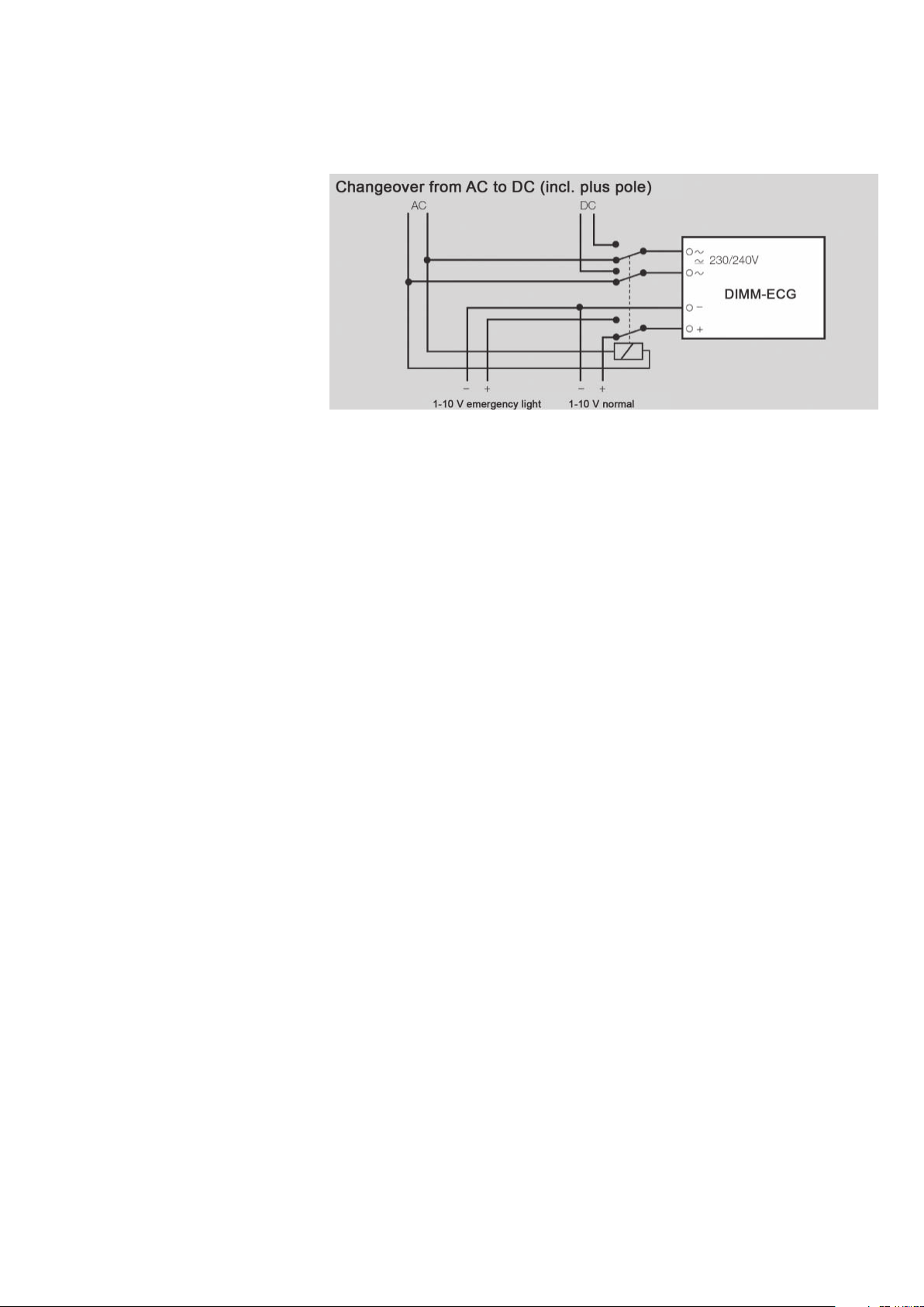
Figure 31: Emergency lighting with 1…10 V DIM ECG
It must be noted that some accessory components (e.g. DIM SA sig-
nal amplifiers) are not approved for battery operation. Therefore, it is
important to make sure that these components are never connected
to DC voltage. In this case the signal amplifier, for example, constitutes a fixed resistance that is connected to the control line. The dimmer setting of an ECG is then around 20 %, and accordingly higher
for more than one.
3.7 Terminals/Cable cross-sections/Wire stripping lengths
For the combined terminals used in the QTi DALI/DIM for T5 and T8
fluorescent lamps, both solid lines as well as flexible lines are permissible. The contacts of the terminal can be made at the top via a socalled insulation displacement contact and via a plug contact (wire
stripping length 8.5-11 mm). Likewise for ECGs with push terminals
(HF DIM, QTi T/E DALI/DIM), both solid lines (wire stripping length
8.5-9.5 mm) and flexible lines are also permitted provided these are
tinned, ultrasound welded or fitted with wire-end sleeves.
49
Page 51

3.7.1 Inserting and releasing the connection cables
Manual cabling of the insulation piercing connection device (above)
with the WAGO insertion tool, e.g. order number: 206-831
Figure 32: Wago insertion tool
Detachment of the contacts (below) with the WAGO 206-830
extraction tool.
1. Insert extraction tool into the line guide above the line
2. Pull out line
Figure 33: Wago extraction tool
Alternatively, the plug contact can be released by simultaneous twist-
ing and pulling.
Release by twisting and pulling
Release by twisting and pulling
Figure 34: Removing the plug contact
The wire stripping lengths and wire cross-sections are printed on the
equipment.
or with the aid of the extraction
tool, order no. 0206-0830
50
Page 52

3.7.2 Cable cross sections
Single-wire conductor Multi-wire conductor
Insulation displacement contact
(IDC contact)
Plug contact 0.5…1.0 mm
Push terminal 0.5…1.5 mm
max. 0.5 mm
²
²
²
max. 0.75 mm
0.5…1.0 mm²
(with wire-end sleeve)
0.5…1.5 mm
(with wire-end sleeve)
²
²
Table 6: Typical cable cross sections of plug and insulation displace-
ment contacts
3.7.3 Basic insulation
IEC 61347 demands basic insulation between the control circuit and
mains supply for control inputs. The DALI standard (IEC 62386) is
related to this. Consequently, the DALI line is “only” basically insulated
and must be treated like the mains voltage for this reason as is the
1…10 V interface.
3.7.4 Lamp holders
The lamps must be mechanically secure and make contact in the
lamp sockets. The holders must be selected according to the type of
ECG/lamp used.
3.7.5 Master/slave circuit
(2-lamp ECG for the operation of 2 single luminaires) Master/slave
operation with multilamp dimmers is not permitted. This is because of
the capacitive leakage currents that can lead to imbalances, different
luminances and unstable operation in the dimmed state (flickering).
3.7.6 Minimum reflector gaps
The reflector must never rest on the lamp, otherwise this can lead to
vibrations and noise emissions. A minimum gap of 6 mm must be
maintained between the lamp and the reflector in all luminaires. If the
gap is less, this can lead to different brightnesses along the length of
the lamp due to the capacitive leakage currents. Flickering can also
occur.
51
Page 53

3.8 Temperature response of dimmable ECGs from OSRAM
Permissible standard values for minimum ambient light tempera-
tures:
Lamp type Min. temperature
at 1 % (3 % CFL)
dimmer setting
T8/26 mm lamp*** -20 °C* 1 %*
T5/16 mm lamp*
HE 14…35
HO 49
HO 24…80
DULUX L* +10 °C 30 %
DULUX D/E, T/E, FC +10 °C** 50 %
+10 °C 60 %****
Min. dimmer setting of
-20 °C to +10 °C
50 %
30 %
Table 7
* Only with QTi…DIM ** 3…100 % *** L18 W, L36 W, L58 W, not
L70 W ****; The critical point from which the maintaining voltage
increases excessively for cold HO lamps lies just below the 30 % dimmer setting. For HE lamps, this point is reached at the same power density. Because of the 100 % power being approx. only half as
high, the dimmer setting is 60 % here. The HO49 lies between HE
14…35 W and HO 24…80 W/Dimming of the amalgam lamps T5 HO
CONSTANT (24 W, 39 W, 54 W, 80 W), CFL (DL CONSTANT 40 W,
55 W, 80 W and T/E IN PLUS 26 W, 32 W, 42 W, 57 W) is possible.
The temperature range of the luminaires can be expanded down-
wards by raising the lowest dimmer setting until the light has reached
a higher inner temperature, otherwise flickering or/and starting problems of the lamp can be expected. From the end of 2008 units do this
automatically.
3.8.1 Intelligent thermal management in hot luminaires
Intelligent thermal management enables operation in a wide ambient
temperature range through power reduction.
From the generation at the end of 2008, the QTi (DALI)…DIM ECG
from OSRAM include the feature of intelligent temperature regulation.
Features
• Notable increase in the light yield (lm/W) of hot luminaires
• Virtually no loss of luminous flux (lm) compared with uncontrolled
operation
• No reduction in the service life of the ECG within the control range
• Simplifies the safety approval of hot luminaires
• Relieves luminaire components
52
Page 54

Note:
Tc temperature [°C]
thermal management without limitation of the temperature
with thermal management
Abscissa: Luminaire ambient temperature [°C]
• Limits the t
temperature to < 80 °C (depending on installation con-
c
dition), but never switches the ECG due to excessive temperature
• Thermally problematic luminaires do not necessarily become stan-
dard conformant devices, even with these ECGs
• Power reduction is carried out up to 50 % of full load operation
Functionality
The ECG measures the ECG temperature once per minute. At the
selected limiting temperature it begins to reduce the power in order to
lower the temperature of the luminaire and to prevent the temperature
of the ECG from increasing further. The T
temperature lies between
c
75 °C and 80 °C depending on installation conditions (e.g. heat coupling into the ECG from top or bottom).
A reduction of the system power by 10 %-20 % at an ambient tem-
perature of 25 °C is sufficient in most cases even in hot luminaires,
however, only approx. 1 %-2 % light is lost because the level of efficiency of the system increases.
Dimming is always possible the temperature regulation may affect
the upper dimming level only significantly.
The regulation of the lamp power compensates the loss of light
!
output in hot luminaires.
120
110
100
90
80
70
60
50
40
30
20
10
0
0 5 10 15 20 25 30 35 40 45 50 55
Figure 35: Dimmable QTi ECG from OSRAM keep their tempera-
ture at the T
measuring point constant within wide limits and
c
thereby also the temperature in the luminaire. As a result, both the
ECG and all other luminaire components are relieved.
53
Page 55
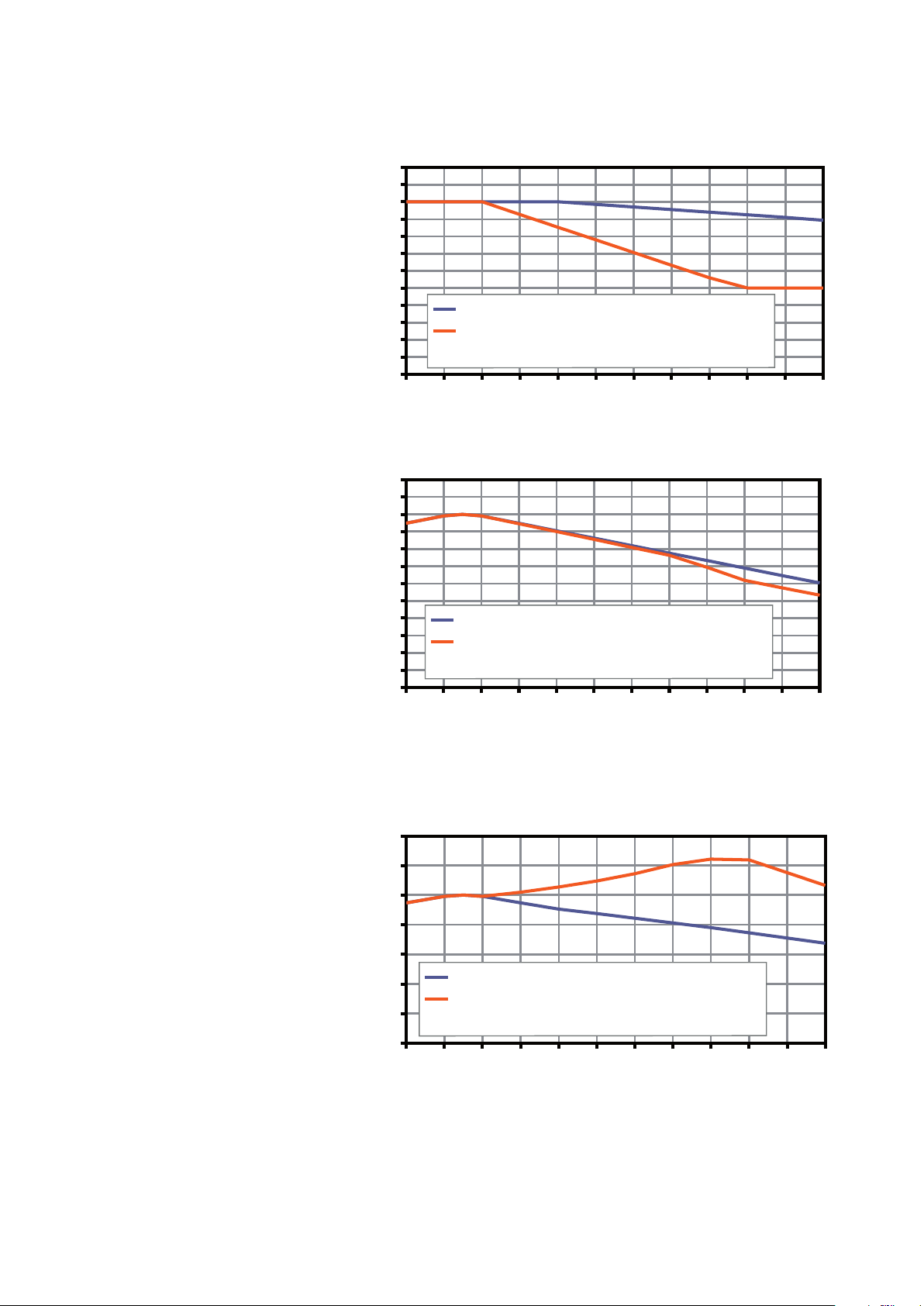
120
thermal management without limitation of the temperature
with thermal management
Abscissa: Luminaire ambient temperature [°C]
thermal management without limitation of the temperature
with thermal management
Abscissa: Luminaire ambient temperature [°C]
thermal management without limitation of the temperature
with thermal management
Abscissa: Luminaire ambient temperature [°C]
a [°C] Tc [°C] Telko [°C] Licht [%] Pn [W]
110
100
0 68 70 110 165 110 110
90
5 73 75 115 165 115 115
7,5 75,5 77,5 116 165 116
80
10 78 80 115,0 165,0 115,0 115,0 115
70
15 78 80 109,5 152,9 106,5 109,7 110
60
20 78 80 104,0 140,7 98,1 104,4 105
25 78 80 98,5 128,6 89,6 99,1 100
50
30 78 80 92,9 116,5 81,2 93,8 95
40
35 78 80 87,4 104,3 72,7 88,5 90
30
40 78 80 81,9 92,2 64,3 80,6 85
45 78 80 76,4 80,1 55,8 71,8 80
20
Rel. output [%]
50 83 85 71,4 80,1 55,8 66,8 75
10
55 88 90 66,4 80,1 61,8
0
0 5 10 15 20 25 30 35 40 45 50 55
Figure 36: This is achieved by a reduction of the system power.
120
110
100
90
80
70
60
50
40
30
20
10
Rel. luminous flux [%]
0
0 5 10 15 20 25 30 35 40 45 50 55
Figure 37: Even so the luminous flux of the luminaire hardly de-
creases because the level of efficiency of the system increases due
to the temperature limitation.
140
120
100
80
60
40
20
Rel. light output [%]
0
0 5 10 15 20 25 30 35 40 45 50 55
Figure 38: The clear rise in the relative light output shows that the
temperature limitation has a positive effect on the energy saving of
hot luminaires.
Measurements using an example of a narrow 2x80 W luminaire:
The precise scaling depends on the type of luminaire and the installa-
tion conditions of the ECG.
54
Page 56
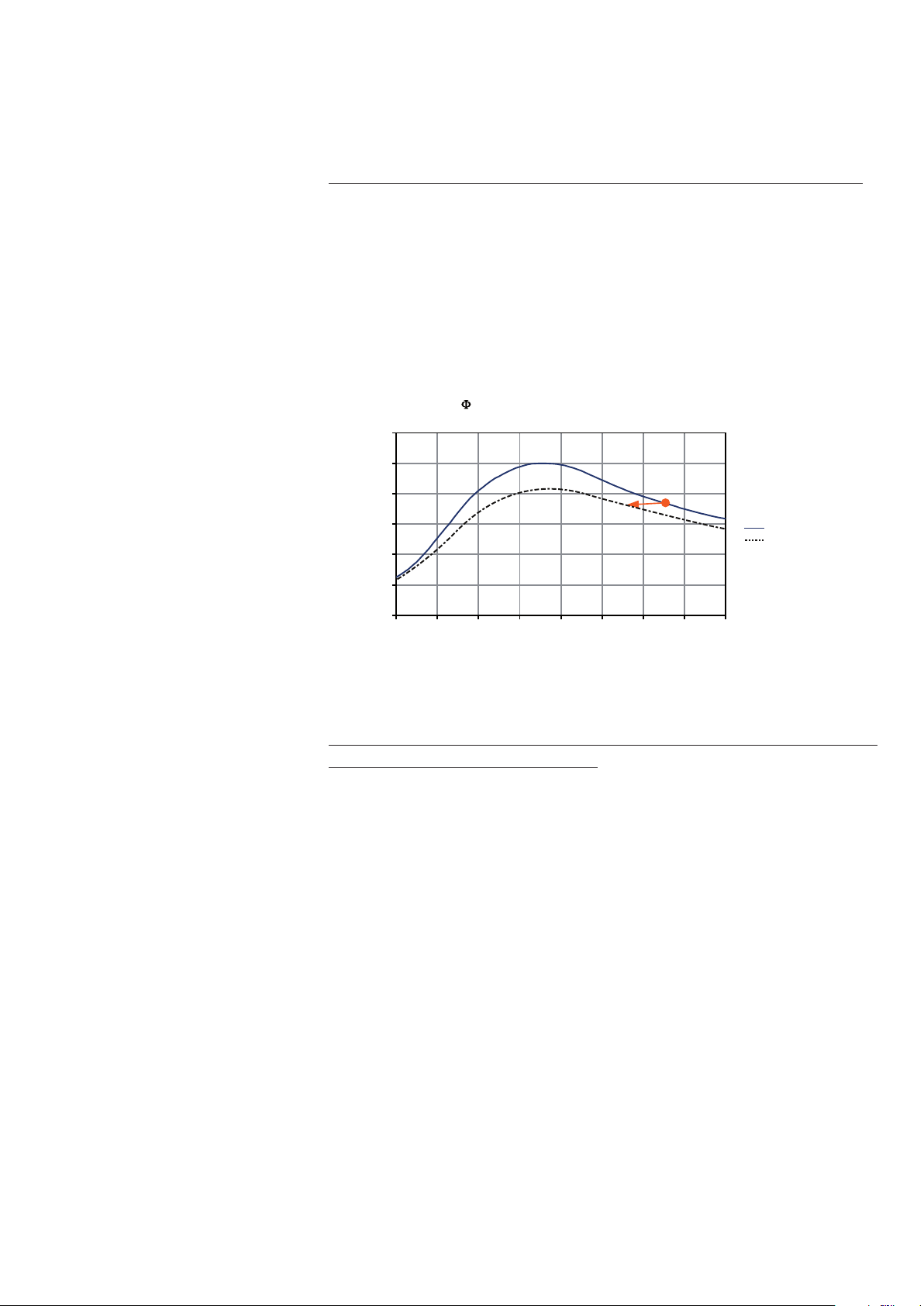
Why are the light losses so small due to the temperature limitation?
Assuming a luminaire whose inside temperature (= lamp ambient
temperature) is to be lowered from 65 °C to 55 °C. A reduction of
the system power by 20 % is required for this. The diagram shows the
Φ(T) curves of T5 lamps for 100 % and 80 % system power.
During the transition from the 100 % curve to the 80 % curve and the
lowering of the lamp ambient temperature by 10 °C, the luminous
flux remains roughly the same.
(T) curves of T5 lamps
120
100
80
60
40
20
Relative luminous flux [%]
0
0 1020304050607080
Lamp ambient temperature [°C]
temperature
regulation
10 0 % system power
80 % system power
Figure 39: Temperature regulation and relative luminous flux
QTi (DALI)…DIM never stop thinking: Instructions for the ther-
mal coupling of lamp and ECG
Temperature limitation is control engineering in the classical sense
and requires, therefore, a closed control loop: The lamps must be
able to heat the ECG. This is ensured when the ECG and lamps are
!
housed in the same luminaire space, separated by a reflector if necessary.
If the ECG is mounted outside the luminaire, it cannot exploit the ben-
efits of the thermal managment.
55
Page 57

3.8.2 Color temperature
Between the maximum and minimum luminous flux of the lamp the
color temperature of the lamp changes – in a DULUX L this is approx.
150 Kelvin. Due to the great difference in luminance density, the color
difference appears to be visually considerably greater. As a result, the
subjective perception of the human eye does not reflect the objective
color temperature change. Directly after changeover from maximum
to minimum luminous flux, a temporary color displacement of up to
400 Kelvin occurs (displacement to the red end that decreases after
approx. 30-40 minutes to the color difference mentioned above (stabilization phase)).
Figure 40: Color-phase diagram acc. to DIN 5033
Note:
Measurement of the most similar color temperature with greatly
dimmed lamps places the highest demands on the electronics and
receiver of the color measuring device. Incorrect valuations cannot be
excluded with conventional color measuring devices.
3.8.3 Outdoor applications
For applications out of doors a special OSRAM housing, the
“OUTKIT”, is available for protecting the ECG against humidity. It is
available for ECGs with a headroom of 30 mm or even 21 mm, in the
lengths of 360 mm and 423 mm. Details of this can be found in the
current light program. For outdoor applications the temperature range
of the system lamp-ECG should be examined in detail. In all outdoor
applications attention must be paid to sufficient mains quality (above
all, lightning protection) so that the ECGs are not damaged.
56
Page 58

3.8.4 Functional test of luminaires
The dimmable QTi family from OSRAM (DALI and 1…10 V) gives in
the luminaire test (with 10 Ω filaments) the following power per lamp:
1-lamp/2-lamp (T5 and T8): 32 Watts
3-lamp/4-lamp (T5 and T8): 16 Watts
This function is independent of the deployment of the actual lamp.
For special applications/luminaires, the filament detection can be
switched off – details on request.
If the end test of the luminaire is carried out in TouchDIM mode,
note that the lamp must be dimmed to 100 % light before the disconnection of the luminaire from the mains supply . Only in this way is
it ensured that the light can also be switched on with the protection
(without control unit) (DALI standard) during installation of the luminaire. If the luminaire was switched off via TouchDIM the luminaire
also remains off after a loss of voltage – the installer could mistakenly
assume a defective ECG in this case.
If the luminaire has mains voltage applied to it for the first time (without
control unit), it must be switched on with 100 % luminous flux (= DALI
factory setting). The changeover of DALI to TouchDIM mode or vice
versa, assumes a mains voltage failure of the ECG (safety interlock).
3.9 Dimming of amalgam lamps
Features
• Stable dimming operation down to 1 % (CFL 3 %)
• Considerably more light in a wide ambient temperature range
• 90 % luminous flux from 0 °C to +70 °C (temperature-dependent
• Reliable lamp ignition down to -20 °C
• Power boost stabilizes discharges in the “pink-phase"
• No service life reduction of lamp/ECG
lamp/ECG combinations
• T5: HO CONSTANT: 24 W, 39 W, 54 W, 80 W
Dimming range 1…100 %
• CFL: DULUX L CONSTANT 40 W, 55 W, 80 W
Dimming range 1…100 %
• CFL: DULUX T/E IN PLUS 26 W, 32 W, 42 W, 57 W
Dimming range 3…100 %
Since the latest generation of OSRAM QTi DALI/DIM units from the
end of 2008,
now also be dimmed without restriction.
cut-off)
amalgam lamps (provided with red stamping ink) can
57
Page 59
(
(
(
(
(
(
(
Lamp
T5 T5 T5 T5 CFL CFL CFL CFL CFL CFL CFL
ECG
QTi DALI / QTi (1…10 V) 1x14/24 DIM x
QTi DALI / QTi
QTi DALI / QTi
QTi DALI / QTi (1…10 V) 1x35/49/80 DIM
QTi DALI / QTi
QTi DALI / QTi
QTi DALI / QTi
QTi DALI / QTi (1…10 V) 2x35/49/80 DIM
QTi DALI / QTi
QTi DALI / QTi (1…10 V) 4x14/24 DIM
QTi DALI / QTi
QTi DALI / QTi (1…10 V) - T/E 2x18-42 DIM
1…10 V) 1x21/39 DIM xx
1…10 V) 1x28/54 DIM xx
1…10 V) 2x14/24 DIM x
1…10 V) 2x21/39 DIM xx
1…10 V) 2x28/54 DIM xx
1…10 V) 3x14/24 DIM x
1…10 V) - T/E 1x18-57 DIM xxxx
x
HO 24 W CONSTANT
40 W
HO 39 W CONSTANT
HO 54 W CONSTANT
HO 80 W CONSTANT
DL CONSTANT
DL CONSTANT 55 W
x*)
x*)
26 W
DL CONSTANT 80 W
D T/E IN PLUS
xxx
32 W
D T/E IN PLUS
42 W
D T/E IN PLUS
57 W
D T/E IN PLUS
*) Not for flashing operation, dimming operation only possible within the scope of a
special release
Figure 41: ECG lamp combinations (amalgam lamps)
Functionality of QTi DALI/DIM: Power boost and amalgam
lamps
The amalgam releases just as much mercury as is required for the
discharge and, as a result, considerably decreases the luminous flux
at high or low temperatures. After a change of the operational mode,
however, it takes a number of minutes until the mercury balance is
discontinued again. If the lamp is switched off for a prolonged period
– no discharge and no mercury requirement – the amalgam collects
all the mercury. On a restart, therefore, there is initially a lack of
mercury which can be detected by the "pink phase“.
If the lamp is dimmed at the same time, its maintaining voltage can
rise to non permitted values and the discharge can become instable. Here the power boost of the QTi DALI/DIM comes into play: It
automatically increases the lamp power in order to lower the
lamp voltage and to stabilize the discharge phase. Then when
the amalgam has released enough mercury, the lamp power is automatically reduced again and the lamp can be dimmed normally.
Also in normal mercury lamps the power boost takes effect and
simplifies dimming during the ignition phase of the lamps as well as for
!
very low temperatures:
When there are instabilities in the lower dimming level, the Power
Boost regulation helps to stabilize the burning conditions.
58
Page 60

Power Boost HO24 CONSTANT
10
9
8
7
6
5
4
Rel. luminous flux [%]
ECG power [W]
3
2
1
0
-20 0 20 40 60 80 100 120 140 160 180 200
Time [s]
Figure 42: Power boost and lamp start with HO 24 W CONSTANT
lamp
Functionality of QTi DALI/DIM: Relative luminous flux > 90 %
over an additional expanded temperature range from 0 °C to
+70 °C
Mercury T5 lamps reach their luminous flux optimum at an ambient
temperature of 35 °C – but only if their mercury household is not
influenced by additional electrode heating. The QTi DALI/DIM units,
therefore, have a cut-off, i.e. the electrode heating is switched
off when it is not needed.
It can be shown that, at low ambient temperatures, amalgam lamps
give off more light when the electrodes are heated somewhat.
Neu!New!
At high temperatures, however, this effect is reversed. The QTi DALI/
DIM uses its internal temperature sensor in order to switch off
the electrode heating at a sufficiently high temperature.
This means a further increase of the luminous flux of cold amalgam
lamps is achieved: The temperature at which the luminous flux
falls below the 90 % line drops from +5 °C to 0 °C.
59
Page 61
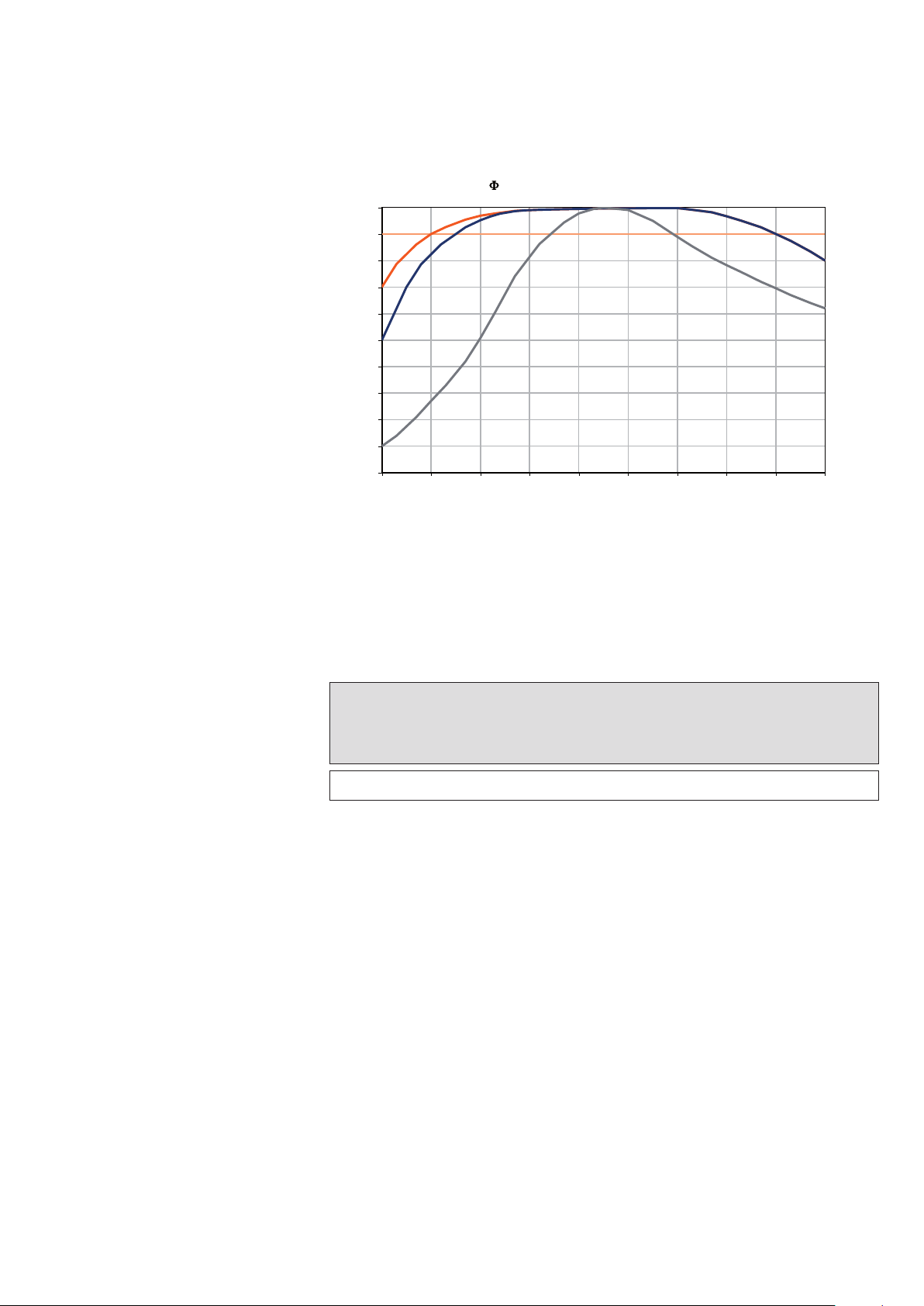
(T) curves of T5 lamps
100
90
80
70
60
50
40
30
Relative luminous flux [%]
20
10
0
-10 0 10 20 30 40 50 60 70 80
Lamp ambient [°C]
-- 90%
-- T5 Standard
-- T5 CONSTAN T
-- T5 CONSTAN T
of dimmable standard ECG
of QTI DALI/DIM
Figure 43: QTi DALI/DIM: More luminous flux over an expanded tem-
perature range
Lamp type Min.
temperature at
1 % (3 % CFL)
Min.
dimmer setting of -20 °C to
+10 °C
dimmer setting
T5, CFL* +10 °C 30 %
Table 8: *Amalgam lamps, T5 HO
CFL (DL
CONSTANT
40 W, 55 W, 80 W)
CONSTANT
(24 W, 39 W, 54 W, 80 W),
Attention: For T/E IN PLUS 26 W, 32 W, 42 W, 57 W a dimmer setting
of 50 % min. applies at -20 °C.
3.9.1
Dynamic dimming procedures with amalgam lamps
The frequency of dimmer setting changes is primarily limited by the
inertia of the control input, a passage of the dimming range takes approx. 200 ms for 1…10 V, and approx. 50 ms for DALI. Thus, rapid
flashing blurs to a middle dimmer setting. At 10 Hz, this effect is already particularly visible at 1…10 V. No damage to the lamp is to be
expected. A dimming process every 2 s is possible without any problem.
60
Page 62
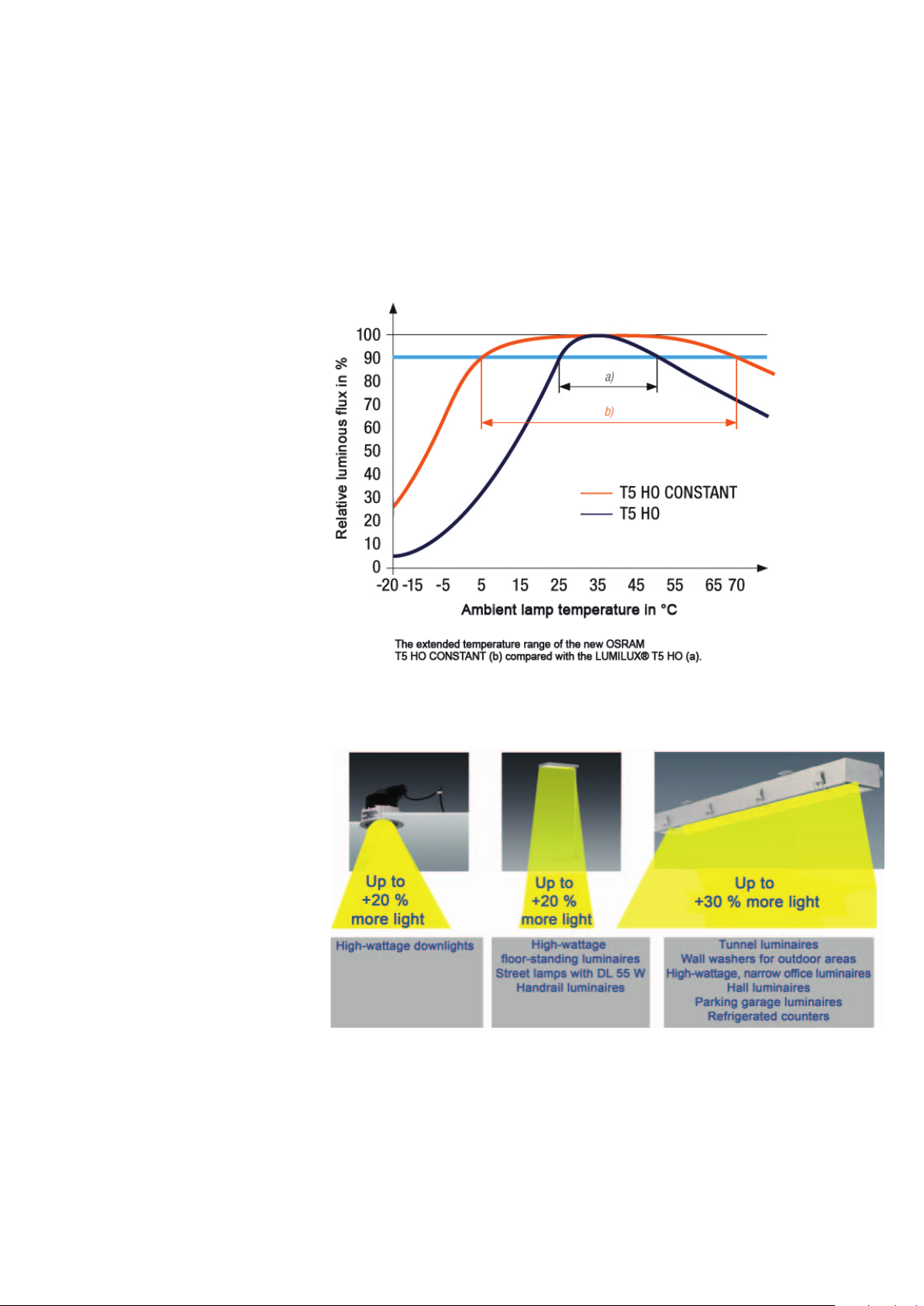
3.9.2 Benefits of amalgam technology
Dimming of amalgam lamps is also suitable for outdoor applications.
Note:
Sufficient attention should be paid that the ECG is protected against
external influences (IP67).
Figure 44: Relative luminous flux against ambient temperature in the
luminaire of T5 standard and T5 HO CONSTANT lamps
Figure 45: More light from new luminaires thanks to amalgam tech-
nology
61
Page 63

Note:
•
•
• Amalgam and mercury lamps must never be mixed in multilamp
ECGs because the power increase available in amalgam lamps
would lead to a vigorous overshooting of the light in a mercury
lamp. In addition, the synchronization in the lower dimming range
would be poor.
• No release: Dimming of a T5 amalgam lamp with predecessor
units up to the end of 2008 (DALI and 1…10 V):
- Voltage peaks arise through unwanted controller oscillations
• For dimmer settings below 30 %, the following applies:
14
- Unfavorable operating condition leads to lamp flickering and a
reduction of the lamp service life
• Recommendation: Dimming of amalgam lamps is possible,
but this is not released by OSRAM. Burning-in of the lamps
at 100 % luminous flux after each restart for approx.
2-3 minutes, then dimming. In principle, however, dimming of
T5 amalgam lamps with predecessor units is not recommended
for the reasons mentioned above.
14
Oscillations – typically in the lower third of the dimming range – can develop
when fluorescent bulbs with electronic control gear are dimmed, which are
caused by the interaction of lamp characteristic, lamp time constants, resonant
circuit and control.
62
Page 64
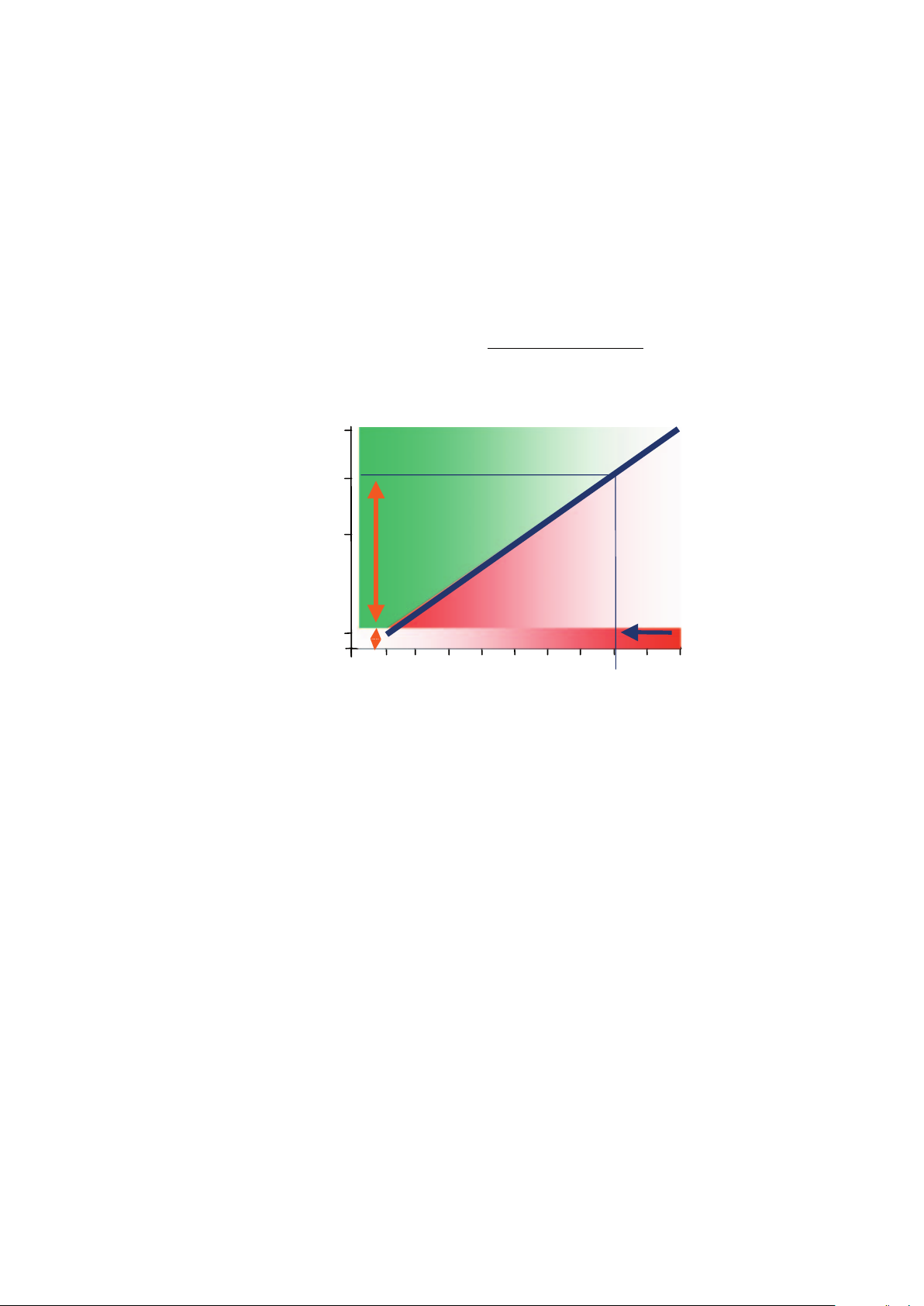
4 System energy consumption
and dimmer setting
Because there is a largely linear relationship between the power
consumption of the DALI/DIM systems (lamp and ECG) and the dimmer setting, the power consumption PN(d) can be calculated for
each dimmer setting d (in percent) from the values PN100 % (100 %
nominal power, PN = Power Nominal) and PN1 % (nominal power of
1 %) (depending on ECG lamp combination, available on request):
%1)( v
PNdPN
d
%1%100
PNPN
%)1(
%99
100 %
Additional savings
80 %
Savings
50 %
Energy consumption (system)
4-10 %
(1/3 own consumption + 2/3 lamp heating)
1 %
Figure 46: Linear relationship, dimmer setting and energy consump-
tion system
Consumption
Luminous flux
Reduction of the new
value in acc. with EN12464
100 %
63
Page 65

5 Dimming of compact fluores-
cent lamps
FC 22W
DULUX D/E 26W
DULUX D/E 18W
DULUX T/E 26W (IN)
DULUX T/E 18W
DULUX T/E 32W
(IN)
FC 40 W
DULUX T/E 42W
(IN)
DULUX T/E 57W
(IN)
Figure 47: Range of lamps with an ECG, www.osram.com/qti
With the new CFL MULTI lamp ECGs, DULUX T/E 18 W as well as T/E
57 W can be operated on one ECG. All 2-lamp downlights for 2x18,
2x26, 2x32 and 2x42 W can be fitted with only one 2-lamp QTi DIM
ECG.
Optionally, with DALI/TouchDIM or TouchDIM Sensor interface can be
ordered
15
. The user can continuously adjust the required lighting level
by dimming.
DALI MCU
Remote switch
without battery
Radio receiver
Figure 48: The QTi T/E DALI system
15
Operation with a 1…10 V interface is also possible (QTi-T/E 1x18-57 DIM and
QTi-T/E 2x18-42 DIM)
64
Page 66
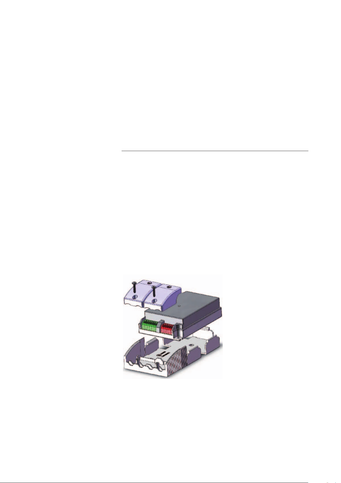
5.1 Unique features of the new OSRAM CFL ECG
• Up to 12 lamp types can be operated on 1-lamp ECG
DULUX D/E 18 W, DULUX T/E 18 W 2
DULUX D/E 26 W, DULUX T/E 26 W )
+ DULUX T/E 26 W IN (amalgam) 3
DULUX T/E 32 W, DULUX T/E 32 W IN (amalgam) 2
DULUX T/E 42 W DULUX T/E 32 W IN (amalgam) 2
DULUX T/E 57 W IN (amalgam) 1
FC 22 W 1
FC 40 W 1
Σ = 12 lamps
• For the first time, DULUX IN (amalgam) can also be operated on
the DIM ECG
• Halving of the range of ECG products from 4 to 2 types of ECG
• Lamp starting with optimized filament preheating inside 0.6 s
• 2-lamp ECGs now as small as 1-lamp ECGs (K3 housing)
• Dimming range 3…100 % luminous flux
• DALI and TouchDim interface can be operated in an ECG, e.g. on
DALI dimmer or TouchDim sensor
• Highest energy efficiency thanks to cutoff technology
• Automatic safety shutdown on lamp defect and at the end of the
lamp life (EoL T2)
• Optional cable clamps for snapping into the housing
Figure 49: Principle Optional cable clamps for snapping into the
housing
65
Page 67
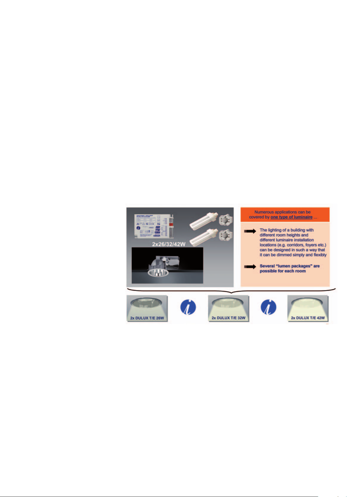
Numerous applications in the downlight sector can be covered by
one luminaire type in combination with the new QTi T/E DALI/DIM
generation from OSRAM. Thus, for example, it is possible to design
the lighting of a building with different room heights and different
luminaire installation locations (e.g. corridors, foyers etc.) so they are
simple and flexible to dim. Thus, several “lumen packages" are pos-
sible for each room. Due to optimized filament preheating, the lamp
starts inside 0.6 seconds which means the user does not have to
accept unnecessary waiting periods after switching on.
The intelligent QTi T/E DALI/DIM units automatically adjust the fila-
ment preheating for very low temperatures. Thus, amalgam lamps
can be operated in a stable way.
Intelligent power reduction at excessive temperatures ensures a
high service life and reliable operation.
Figure 50: QTi T/E 2x26-42 W DALI/DIM: Realizable in a single lumi-
naire
66
Page 68

6 The Activity Group DALI
(AG DALI)
The “DALI" workgroup was set up in 1999 under the auspices of the
ZVEI (the German Central Association of Electrical Engineering and
the Electrical Industry) with the aim of establishing this new standard
on the market. All the leading manufacturers of ECGs and controllers
are represented in this Activity group so they can develop and market
their products in accordance with the requirements of the DALI stan-
dard. The AG DALI is an open community that any company can join
for a modest annual fee.
The AG DALI has published a “DALI Handbook” and various other in-
formation brochures that can be downloaded from their home page.
See: www.dali-ag.org
Contact address:
Activity Group DALI
des ZVEI e.V., Fachverband Elektroleuchten
Lyonerstr. 9
D-60528 Frankfurt am Main
Tel.: +49 (0)69 63 02-0
Fax: +49 (0)69 63 02-317
Email: licht@zvei.org
67
Page 69

7 Tender documents
QUICKTRONIC® INTELLIGENT DALI DIM for compact fluores-
cent lamps
Ordering designation according to lamp type: QTi DALI-T/E …
DIM
• Intelligent ECG with DALI interface according to IEC 60929
• Compact fluorescent lamps, OSRAM DULUX
42 W and OSRAM DULUX
®
T/E IN 26, 32, 42 (57) W (amalgam lamps) from 3 % to 100 % can
be dimmed without any restriction
• Warm start of the lamp inside 0.6 seconds without switch-on flash
• Manual dimming operation (TouchDIM ) without any control gear
with standard installation switches, incl. memory function (doubleclick) and soft start
• Service life: 50,000 h at maximum thermal load (t
10 % failure)
• Effective excess temperature protection of the dimming ECG
through intelligent power reduction at high t
• 5-year system+ guarantee:
For every ECG that failed due to a material or production fault, a
replacement is available
• CELMA energy classification EEI = A1
• Maximum energy efficiency thanks to cut-off technology
• EoL shutdown acc. to EN/IEC 61347-2-3 Section 17
• For use in emergency lighting systems acc. to EN 50172 / DIN VDE
0108-100
• Configurable emergency current features, adjustable light value
without control signal between 100 % and 3 % luminous flux
• Test mark: ENEC, VDE, EMC
• EN 60929, EN 61347-2-3, EN 55015, EN 61000-3-2, EN 61547,
EN 61000-3-3
®
T/E 18, 26, 32,
= 75 °C, max.
c
temperatures
c
QUICKTRONIC
®
INTELLIGENT DALI DIM for T5/Ø 16 mm fluorescent lamps
Ordering designation for each type of lamp: QTi DALI … DIM
• Intelligent ECG with DALI interface according to IEC 60929
• Operation of T5/Ø 16 mm fluorescent lamps of same length in a
luminaire for the flexible adaptation of the lighting level
• Unrestrictedly dimmable from 1 % to 100 %
• Max. dimming speed for dynamic RGB color light applications of
5 ms, from 1 % to 100 % through optimized regulation of the filament preheating
• Warm start of the lamp inside 0.5 seconds without switch-on flash
• Manual dimming operation (TouchDIM) without any control gear
with standard installation buttons, incl. memory function (doubleclick) and soft start
• Service life: 50,000 h at maximum thermal load (t
= 75 °C, max. 10
c
% failure)
• Effective excess temperature protection of the dimming ECG
68
Page 70

through intelligent power reduction at high tc temperatures
• 5-year system+ guarantee:
For every ECG that failed due to a material or production fault, a
replacement is available
• CELMA energy classification EEI = A1
• Maximum energy efficiency thanks to cut-off technology
• EoL shutdown acc. to EN/IEC 61347-2-3 Section 17
• For use in emergency lighting systems acc. to EN 50172 / DIN VDE
0108-100
• Configurable emergency current features
• Light value without control signal adjustable between 100 % and
1 % luminous flux
• Test mark: ENEC, VDE, EMC
• EN 60929, EN 61347-2-3, EN 55015, EN 61000-3-2, EN 61547,
EN 61000-3-3
QUICKTRONIC
®
INTELLIGENT DALI DIM for T8/Ø 26 mm fluorescent lamps
Ordering designation for each type of lamp: QTi DALI … DIM
• Intelligent ECG with DALI interface according to IEC 60929
• Commercial T8/Ø 26 mm fluorescent lamps unrestrictedly dim-
mable from 1 % to 100 %
• Max. dimming speed for dynamic RGB color light applications of
5 ms, from 1 % to 100 % through optimized regulation of the filament preheating
• Warm start of the lamp inside 0.5 seconds without switch-on
flash
• Manual dimming operation (TouchDIM ) without any control gear
with standard installation buttons, incl. memory function (doubleclick) and soft start
• Service life: 50,000 h at maximum thermal load (t
= 75 °C, max.
c
10 % failure)
• Effective excess temperature protection of the dimming ECG
through intelligent power reduction at high t
temperatures
c
• 5-year system+ guarantee:
For every ECG that failed due to a material or production fault, a
replacement is available
• CELMA energy classification EEI = A1
• Maximum energy efficiency thanks to cut-off technology
• EoL shutdown acc. to EN/IEC 61347-2-3 Section 17
• For use in emergency lighting systems acc. to EN 50172 / DIN VDE
0108-100
• Configurable emergency current features, light value without con-
trol signal adjustable between 100 % and 1 % luminous flux
• Test mark: ENEC, VDE, EMC
• EN 60929, EN 61347-2-3, EN 55015, EN 61000-3-2, EN 61547,
EN 61000-3-3
69
Page 71

QUICKTRONIC® INTELLIGENT DIM (1…10 V) for compact fluorescent lamps
Ordering designation for each type of lamp: QTi-T/E…DIM
• Intelligent ECG with 1…10 V interface acc. to IEC 60929
• OSRAM DULUX compact fluorescent lamps
and OSRAM DULUX
®
T/E IN 26, 32, 42 (57) W (amalgam lamps)
®
T/E 18, 26, 32, 42 W
unrestrictedly dimmable from 3 % to 100 %
• Warm start of the lamp inside 0.6 seconds without switch-on
flash
• Service life: 50,000 h at maximum thermal load (t
= 75 °C, max.
c
10 % failure)
• Effective excess temperature protection of the dimming ECG
through intelligent power reduction at high t
temperatures
c
• 5-year system+ guarantee:
For every ECG that failed due to a material or production fault, a
replacement is available
• CELMA energy classification EEI = A1
• Maximum energy efficiency thanks to cut-off technology
• EoL shutdown acc. to EN/IEC 61347-2-3 Section 17
• For use in emergency lighting systems acc. to EN 50172 / DIN VDE
0108-100
• Test mark: ENEC, VDE, EMC
• EN 60929, EN 61347-2-3, EN 55015, EN 61000-3-2, EN 61547,
EN 61000-3-3
• Ordering designation for each type of lamp: QTi-T/E…DIM
QUICKTRONIC
®
INTELLIGENT DIM (1…10 V) for T5/Ø 16 mm
fluorescent lamps
Ordering designation for each type of lamp: QTi … DIM
• Intelligent ECG with 1…10 V interface acc. to IEC 60929
• Operation of T5 fluorescent lamps of the same length in a luminaire
for the flexible adaptation of the light level
• Unrestrictedly dimmable from 1 % to 100 %
• Max. dimming speed for dynamic RGB color light applications of
5 ms, from 1 % to 100 % through optimized regulation of the filament preheating
• Warm start of the lamp inside 0.5 seconds without switch-on
flash
• Manual dimming operation (TouchDIM) without any control gear
with standard installation buttons, incl. memory function (doubleclick) and soft start
• Service life: 50,000 h at maximum thermal load (t
= 75 °C, max.
c
10 % failure)
• 5-year system+ guarantee
For every ECG that failed due to a material or production fault,
a replacement is available
• CELMA energy classification EEI = A1
• Maximum energy efficiency thanks to cut-off technology
70
Page 72

• EoL shutdown acc. to EN/IEC 61347-2-3 Section 17
• For use in emergency lighting systems acc. to EN 50172 / DIN VDE
0108-100
• Test mark: ENEC, VDE, EMC
• EN 60929, EN 61347-2-3, EN 55015, EN 61000-3-2, EN 61547,
EN 61000-3-3
QUICKTRONIC
®
INTELLIGENT DIM (1…10 V) for T8/Ø 26 mm
fluorescent lamps
Ordering designation for each type of lamp: QTi … DIM
• Intelligent ECG with 1…10 V interface acc. to IEC 60929
• Commercial T8/Ø 26 mm fluorescent lamps unrestrictedly dim-
mable from 1 % to 100 %
• Unrestrictedly dimmable from 1 % to 100 %
• Max. dimming speed for dynamic RGB color light applications of
5 ms, from 1 % to 100 % through optimized regulation of the filament preheating
• Warm start of the lamp inside 0.5 seconds without switch-on
flash
• Manual dimming operation (TouchDIM) without any control gear
with standard installation buttons, incl. memory function (doubleclick) and soft start
• Service life: 50,000 h at maximum thermal load (t
= 75 °C, max.
c
10 % failure)
• 5-year system+ guarantee:
For every ECG that failed due to a material or production fault,
a replacement is available
• CELMA energy classification EEI = A1
• Maximum energy efficiency thanks to cut-off technology
• EoL shutdown acc. to EN/IEC 61347-2-3 Section 17
• For use in emergency lighting systems acc. to EN 50172 / DIN VDE
0108-100
• Test mark: ENEC, VDE, EMC
• EN 60929, EN 61347-2-3, EN 55015, EN 61000-3-2, EN 61547,
EN 61000-3-3
71
Page 73

8 Frequently asked questions
(FAQ)
8.1 DALI part
8.1.1 TouchDIM
• Can the TouchDIM function and a DALI controller be used at
the same time?
No. Either a DALI controller or the TouchDIM function! TouchDIM
and DALI operation are mutually exclusive.
• How do the ECGs behave after a mains voltage failure?
The DALI ECG of the QTi series automatically reestablish the previ-
ous status. Both the switching status (on/off) and the dimmer setting are taken into account here.
• Can devices that do not run synchronously be synchronized
again?
Yes. The procedure is as follows:
Press switch for long period (> 3 s) (all ECGs on).
Press switch for short period (all ECGs are switched off).
Press switch for long period (all ECGs switch on with minimum
dimmer setting and then fade up) ! Long – short – long
• Is it also possible to connect more than one DALI ECGs to a
switch?
Up to 6 ECGs can be controlled by one switch, the number of con-
trol sections is limited to 2. With one DALI repeater, up to 64 DALI
ECGs can be operated in TouchDIM mode.
• How long should the cable be between the switch and the
ECG?
The line length should not exceed 25 meters. In the case of longer
lines, additional measures must be taken in order to suppress interference (e.g. bell transformer).
• Which switches can be used?
All button can be used that are suitable for mains voltage, but no
button with glow lamps.
• Does TouchDIM only work with 230 V AC voltage?
No, TouchDIM control is possible with AC voltages between 10 V
and 230 V (effective value!).
• Can I also use DC voltage for TouchDIM?
No, it must be AC voltage with a frequency between 46 and
66 Hz.
72
Page 74

• Can a TouchDIM system be upgraded with a DALI control-
ler?
Yes, an upgrade is possible at any time. Changeover of the DALI
ECGs from TouchDIM to DALI takes place automatically after a
power outage on the ECG when the first DALI command is sent.
TouchDIM and DALI control cannot be used at the same time!
• Can the motion function of the TouchDIM sensor be
switched off (holiday mode)?
Yes, the so-called "holiday mode" prevents the lighting system be-
ing switched on by the motion sensor. It is activated by doubleclicking on the switch if the light has not been manually dimmed in
the previous 30 seconds. The motion function is active again if the
luminaire is switched on manually at the switch.
8.1.2 DALI in general
• Do the ECGs have to be addressed in DALI?
No, it can also function without addressing (broadcast mode).
• What is the difference between DSI and DALI?
DSI is a corporate solution, not a general standard like DALI. DSI
does not allow digital addressing so it is not possible to form
groups freely or check individual lamps for faults! Groups have to
be formed by wiring as well as in the case of 1…10 V systems.
• Does attention have to be paid to the group arrangement in
DALI when wiring the system?
No, the groups are generally assigned (addressed) when the sys-
tem is started up.
• Does attention have to be paid to the polarity of the DALI
control line?
When OSRAM DALI control gear is used there is no need to worry
about polarity.
• How can DALI ECGs be addressed?
They can be addressed individually, in groups or all together.
• Can I get feedback messages from DALI ECGs?
Yes, all device settings as well as the device status, such as lamp
faults, can be checked.
73
Page 75

• Can a DALI ECG belong to more than one group at the same
time?
Yes. Each DALI controller can belong to up to 16 groups.
• Where are the data for the group assignments and light
scene values stored?
They are stored directly in the internal EEPROM of the ECG.
• Are the data in the ECG lost if there is a power failure?
No, the data are permanently stored in the ECG. They are retained
even if the power failure is prolonged.
• What happens if an ECG fails?
The ECG simply has to be replaced and adjusted to the appropri-
ate settings (the procedure depends on the control unit).
• What happens if a control unit is faulty?
If the DALI interface voltage is lost, all ECGs take on the so-called
"system failure level" (ECG factory setting: 100 % light).
• Can DALI be integrated in superordinate building management systems (e.g. EIB or LON)?
Yes, by using gateways or control units with the appropriate inter-
face.
• Is DALI a competitor to EIB or LON?
No, DALI is only a subsystem of the building management system
for controling the lighting.
• Can 1…10 V components also be incorporated in a DALI
lighting control system?
Yes, by using DALI to 1…10 V converters.
• Can existing 1…10 V lighting systems be upgraded with a
DALI controller?
Yes, a DALI to 1…10 V converter is needed
naire group (e.g. DALI CON 1…10 SO).
• Can the wiring of the DALI ECG be checked on a building
site?
This depends on the control unit used. DALI ECGs that are still in
their factory setting always produce 100 % light when the mains
voltage (with protection) is applied.
for each 1…10 V lumi-
74
Page 76

• What insulation is required for the DALI control line?
The DALI control line must be approved for mains voltage (as in the
case of the 1…10 V interface).
• Can existing 1…10 V control lines be used?
Yes, provided they are rated for mains voltage.
• How long can a control line be?
A maximum of 300 m between the controller and the furthest con-
nected DALI unit.
• Can control and power cables be laid together?
Yes, a 5 x 1.5 mm
2
NYM cable can be used, for example.
• What line cross section must the control line have?
Up to 100 m: min. 0.5 mm2/from 100 m to 150 m: 1.0 mm2/from
150 m: 1.5 mm
2
.
• Can any company develop a DALI controller or DALI ECG?
Yes, there are no restrictions except that the DALI logo
may only be used by members of the DALI Activity Group.
See also http://www.dali-ag.org/.
• What happens if I use DALI ECGs from different manufacturers in the same system?
The controllers are DALI-compatible if they carry the DALI logo. It is
important to note, however, as in 1…10 V technology, ECGs from
different manufacturers can result in different filament preheating
times and different lamp starting times.
• Can controllers from different manufacturers be combined?
No, DALI ECGs are interchangeable, but the control components
cannot normally be combined.
• Is it possible to limit the maximum and minimum luminous
flux?
Yes, these values can be changed/limited with the appropriate
controller in the ECG.
75
Page 77

8.1.3 DALI to 1…10 V converter
• Is it possible to switch and dim
with DALI to 1…10 V converters?
Yes, with the converter both are possible.
• Can the converter also offer the TouchDim function?
Yes, the converter behaves like a DALI ECG here in TouchDIM-
mode 1.
• Why does the converter have characteristic changeover?
8.1.4 Troubleshooting TouchDIM mode
Before you start troubleshooting, please check each time that the
So that it is possible to compensate for the different behaviours
of incandescent lamps and fluorescent lamps. You should therefore choose between the linear characteristic (incandescent lamps)
and the logarithmic characteristic (fluorescent lamps) depending on
whether the converter is operating a fluorescent lamp ECG or a
dimmer for incandescent lamps).
controller is wired according to the operating manual and that the corresponding power supply is on. In the case of luminaires, please also
check the light sources and replace if necessary.
• The ECG are not reacting as expected to switch operations.
If the button was pressed too long (> 1 second), the lamp starts
at the lowest dimmer setting which may be difficult to see in bright
ambient surroundings.
• Individual luminaires have a different brightness level and
conflict with one another.
→ Manual synchronization of the system:
Long button (>3 s) press (all lamps on).
Short button press (all lamps are switched off).
Long button press (all lamps switch on at minimum dimmer setting
and dim upwards).
• The ECGs react without any button being pressed.
1. The line between button and luminaire (ECG) is possibly too
long.
2. A button with glow lamp was used which is not permissible.
• The motion detection function of the TouchDIM sensor is
not working.
1. The luminaire was switched off by double-clicking the switch
and this has deactivated the motion detection function (holiday
mode)
76
Page 78

2. The available daylight is sufficiently bright. Cover the sensor and
observe the response of the luminaire.
3. The motion detection is deactivated for 30 s after the lighting
system has been switched off manually. This time will only expire
if there are no more people in the detection zone.
• The luminaire is not regulating its the brightness to the setpoint value
1. After setting the brightness, you must press the button twice
inside 30 s (to store the setpoint value). If you press the button
later than that, the holiday mode will be activated.
2. The dimming was carried out manually – this deactivates the
brightness control. Switch the luminaire off and on again.
3. No setpoint value has been stored.
Set the required light value and double-click to store it.
• Holiday mode cannot be activated.
The brightness level has been changed within the past 30 seconds
– holiday mode can only be activated after this time.
8.1.5 Troubleshooting DALI controllers
• The ECGs are not reacting to commands from the controller?
Please check the wiring where approx. 16 V
should be applied to
DC
the DALI terminals of the ECG.
8.1.6 DALI to 1…10 V converter
• Not all lighting strips can be switched off.
Please check that the power supply of the relevant lighting group
has been routed via the load contact of the respective converter.
8.2 1…10 V DIM ECG part
• How long can the 1…10 V control line be?
The maximum permissible length of the control line is 100 m (also
applies to the DALI control line). (Note: Due to the low control current, a drop in voltage is only noticeable on the control line after
approx. 300-400 m)
• What line cross section should the 1…10 V control line
have?
1.5 mm² is recommended as the cross section. The insulation of
the line used must be designed for mains voltage.
77
Page 79

• Can control and supply lines be laid together?
•
•
•
Yes, control and supply lines can be laid together (VDE 0100 520
Section 528.11). The following points must be noted:
• The lines used must comply with the maximum operating volt-
age that occurs. (VDE 0100/11.85, T520 Section 528.11)
• When laying core lines in installation ducts or channels, only the
conductor of a main current circuit, including the associated
auxiliary circuits, may be laid.
• Also a number of main current circuits, including the associated
auxiliary circuits, can be laid in one line. (VDE 0100/11.85, T520
Section 528.11)
•
How can permanently selected lighting levels be controlled
simply and economically?
A simple control for preset lighting levels with 100 % or 1 % lumi-
nous flux and several values lying between is possible with fixed
resistors or Zener diodes.
• Can 1…10 V dimmable ECGs from OSRAM be used for emergency lighting?
Yes, but the use of dimmable ECGs in systems for emergency light-
ing is associated with additional expense. Components such as
signal amplifiers, ICM 10 or the light constant holding module would
be destroyed by supplying them with DC voltage. This means that,
in the case of switching over to a DC voltage supply, these components must be disconnected from the mains supply.
• Can compact fluorescent lamps with a 2-pin base be
dimmed?
No, ECG operation of 2-pin lamps is not generally allowed. The
glow igniter integrated in the base can lead to problems such as
poor, unreliable ignition, reduced lamp service life or destruction
of the ECG. Here additional heating of the lamp electrodes is not
possible in dimmed operation which would lead to a significantly
reduced lamp service life. Basically, only 4-pin base lamps with the
designation /E (e.g. DULUX S/E, D/E, T/E) can be operated on the
ECG and dimmed with this.
• Does continuous operation in the lowest dimmer setting
have an effect on the service life of fluorescent lamps?
Long-term operation of fluorescent lamps and ECG from
OSRAM in the dimmed state has no negative influence on the service life of the lamp.
78
Page 80

8.2.1 Troubleshooting 1…10 V
•
•
•
• Lamp does not burn with 100 % luminous flux
The control line is not connected or not correctly connected to the
control unit, or the control unit is not a sufficiently good current sink
and, hence, cannot reduce the control voltage.
Check the wiring. Check that the control voltage is reduced while
dimming and, if necessary, install a parallel resistor in the control
line.
Also one or more control inputs may be pole reversed:
• Disconnect control unit
• Subdivide control circuit
• Further subdivide control circuit
• Lamp always burn at minimum brightness
+ and - connectors of the control line are reversed, or short circuit
in the control line.
Connect lines with correct polarity, check wiring
• The lamp does not show the required luminous flux when
controlled with potentiometers or fixed resistors.
Potentiometers or resistors are wrongly dimensioned. Check the
values
• Insufficient brightness along the lamp
Spacing of the reflector to the lamp is too small, capacitive dis-
charge currents occur.
Increase gap between the reflector and the lamp
• Synchronous lamp flickering
Fault is outside the dimming system, e.g. N conductor disconnec-
tion, control voltage not OK
Check N conductor connection and control unit
79
Page 81
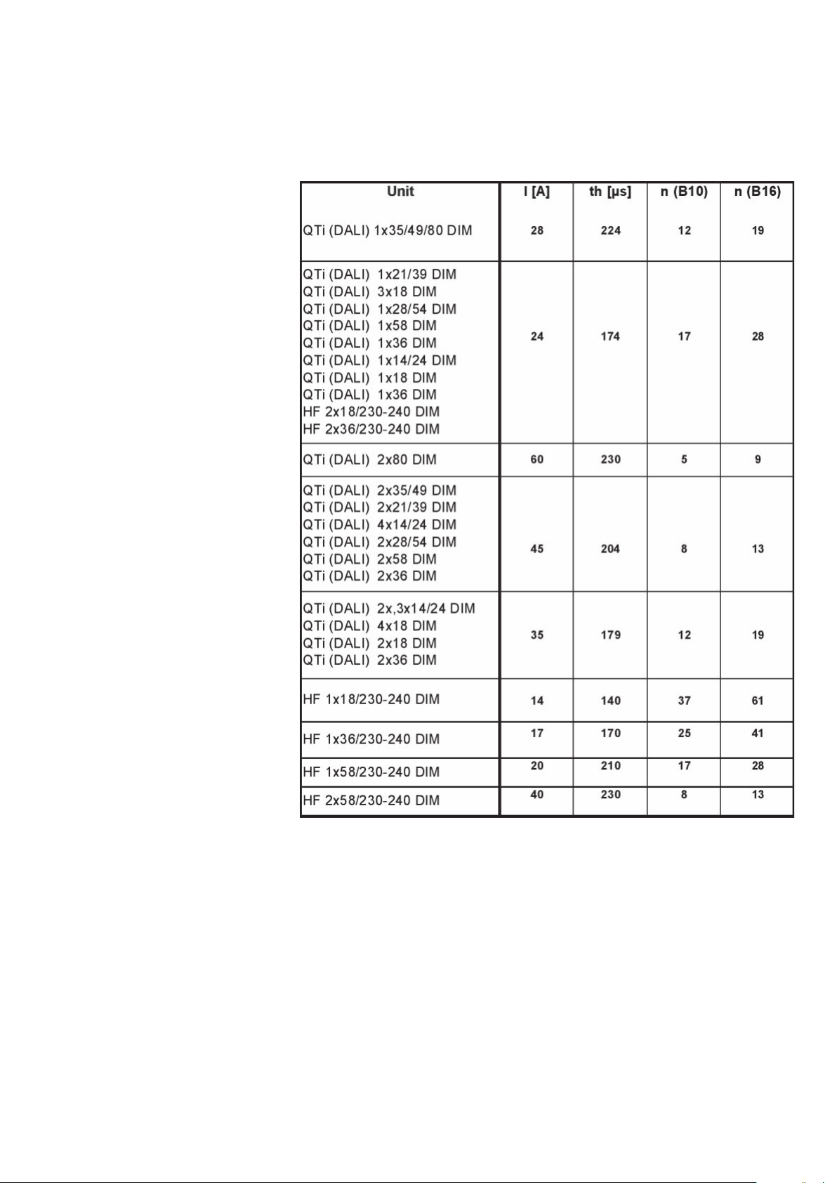
9 Appendix
9.1 Starting currents and max. number of ECGs in automatic cutouts
Figure 51: Starting currents and max. number of ECGs in automatic
cutouts (B characteristic), measurement at U
= 230 V
N
AC
9.1.1 Minimum B/C characteristic triggering levels
The minimum triggering levels increase from B to C characteristic by
the factor = 1.67, i.e. not quite a factor of 2. At the same time, however, the total current must not exceed the value of the automatic
cutouts.
80
Page 82

9.2 DALI fade time and fade rate
The fade time can be set to any of 16 different steps (0 to 15) and
denotes the fade time to go from one scene to another (room lighting
states). The fade rate, which can also be set to any of 16 settings,
is the number of fade steps per second and acts on the speed with
which the lighting is faded up or down manually.
Setting FADE TIME (s) FADE RATE (steps/s)
0 <0.7 Not possible
1 0.7 357.8
2 1.0 253.0
3 1.4 178.9
4 2.0 126.5
5 2.8 89.5
6 4.0 63.3
7 5.7 44.7
8 8.0 31.6
9 11.3 22.4
10 16.0 15.8
11 22.6 11.2
12 32.0 7.9
13 45.3 5.6
14 64.0 3.9
15 90.5 2.8
Table 9: Fade time and fade rate of dimmable OSRAM DALI control-
lers
9.3 Lamp wiring
Figure 52: QTi DALI/DIM 1x: lines 26 and 27 max. length of 1 m
81
Page 83
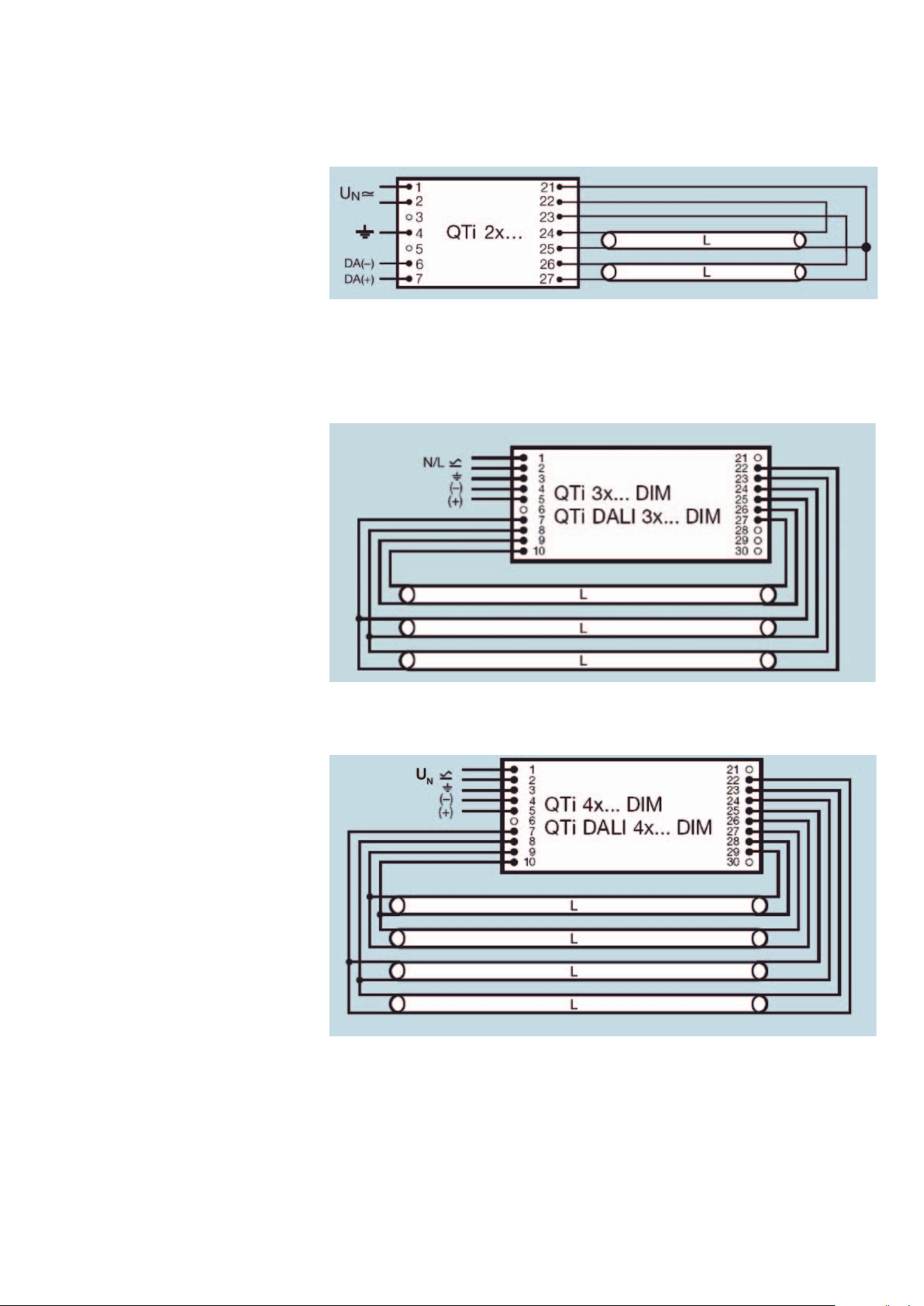
Figure 53: QTi DALI/DIM 2x: lines 24, 25 and 26, 27 max. length of
1 m
Figure 54: QTi DALI/DIM 3x
Figure 55: QTi DALI/DIM 4x
82
Page 84

Figure 56: HF DIM 1x: lines 26 and 27 max. length of 1.5 m
Figure 57: HF DIM 2x: lines 24, 25 and 26, 27 max. length of 1.5 m
83
Page 85

9.4 Operating parameters of the ECG lamp combinations
Unit
QTi DALI 1x14/24 DIM
QTi 1x14/24 DIM
QTi DALI 1x21/39 DIM
QTi 1x21/39 DIM
QTi DALI 1x28/54 DIM
QTi 1x28/54 DIM
QTi DALI 1x35/49/80 DIM
QTi 1x35/49/80 DIM
QTi DALI 2x14/24 DIM
QTi 2x14/24 DIM
QTi DALI 2x21/39 DIM
QTi 2x21/39 DIM
QTi DALI 2x28/54 DIM
QTi 2x28/54 DIM
QTi DALI 2x35/49 DIM
QTi 2x35/49 DIM
QTi DALI 2x35/49/80 DIM
QTi 2x35/49/80 DIM
QTi DALI 3x14/24 DIM
QTi 3x14/24 DIM
QTi DALI 4x14/24 DIM
QTi 4x14/24 DIM
QTi DALI 1x18 DIM
QTi 1x18 DIM
QTi DALI 1x36 DIM
QTi 1x36 DIM
QTi DALI 1x58 DIM
QTi 1x58 DIM
QTi DALI 2x18 DIM
QTi 2x18 DIM
QTi DALI 2x36 DIM
QTi 2x36 DIM
QTi DALI 2x58 DIM
QTi 2x58 DIM
HF 1x18/230-240 DIM
HF 1x36/230-240 DIM
HF 1x58/230-240 DIM
HF 2x18/230-240 DIM
HF 2x36/230-240 DIM
HF 2x58/230-240 DIM
QTi DALI-T/E 1x18-57 DIM
QTi-T/E 1x18-57 DIM
QTi DALI-T/E 2x18-42 DIM
QTi-T/E 2x18-42 DIM
1) AC mains voltage
2) Lamp-dependent values
3) At 100 % luminous flux
Lamps Umin-max 1) Ubatt min-max KHz ECG 2) Nominal
1xHE14
1xHO24
1xDL24 198…264 154…276 53…120
1xHE21
1xHO39
1xDL40 198…264 154…276 44…120
1xHE28
1xHO54
1xDL55 198…264 154…276 44…120
1xHE35
1xHO49
1xHO80 198…264 154…276 44…120
2xHE14
2xHO24
2xDL24 198…264 154…276 53…120
2xHE21
2xHO39
2xDL40 198…264 154…276 44…120
2xHE28
2xHO54
2xDL55 198…264 154…276 44…120
2xHE35
2xHO49 198…264 154…276 44…120
2xHO80
2xHO49
2xHE35 198…264 154…276 44…120
3xHE14
3xHO24
3xDL24 198…264 154…276 53…120
3xHE14
3xHO24
3xDL24 198…264 154…276 53…120
1xL18
1xDL18 198…264 154…276 51…120
1xL36
1xDL36 198…264 154…276 48…120
1xL58
2xL18
2xDL18
2xL36
2xDL36
2xL58 198…264 154…276 46…120 0.49 0.98 110 2x5200
1xL18 198…264 154…276 40…100 0.09 0.95 19 1x1300
1xL36 198…264 154…276 40…100 0.17 0.97 36 1x3200
1xL58 198…264 154…276 40…100 0.25 0.98 56 1x5000
2xL18 198…264 154…276 40…100 0.17 0.97 36 2x1300
2xL36 198…264 154…276 40…100 0.31 0.99 71 2x3200
2xL58 198…264 154…276 40…100 0.48 0.99 111 2x5000
1xT/E18
1xT/E26
1xT/E32
1xT/E42
1xT/E57 198…264 154…276 42…130
1xT/E18
1xT/E26
1xT/E32
1xT/E42 198…264 154…276 42…140
198…264 154…276 46…120
198…264 154…276 51…120 0.17
198…264 154…276 48…120 0.31
current
[A] 3)
0.08
0.12
0.12
0.11
0.20
0.20
0.14
0.27
0.27
0.18
0.24
0.38
0.15
0.24
0.24
0.22
0.39
0.39
0.28
0.54
0.54
0.36
0.48
0.78
0.48
0.36
0.20
0.32
0.32
0.27
0.43
0.43
0.09
0.09
0.16
0.16
0.24 0.99 55 1x5200
0.17
0.31
0.09
0.13
0.16
0.21
0.27
0.17
0.25
0.30
0.39
Lambda W system 3) ln 3)
0.96
0.98
0.98
0.96
0.98
0.98
0.97
0.99
0.99
0.96
0.98
0.99
0.96
0.96
0.96
0.96
0.96
0.97
0.97
0.98
0.98
0.95
0.97
0.98
0.97
0.95
0.97
0.99
0.99
0.97
0.99
0.99
0.97
0.97
0.99
0.99
0.96
0.96
0.98
0.98
0.95
0.97
0.98
0.99
0.99
0.95
0.98
0.99
0.99
17
27
27
24
44
44
31
60
60
39
54
87
34
54
54
48
88
88
62
121
121
78
108
175
108
78
45
73
73
60
98
98
19
19
35
35
38
38
70
70
20
27
39
47
62
35
56
68
90
1x1200
1x1750
1x1800
1x1900
1x3100
1x3500
1x2600
1x4450
1x4800
1x3300
1x4300
1x6150
2x1200
2x1750
2x1800
2x1900
2x3100
2x3500
2x2600
2x4450
2x4800
2x3300
2x4300
2x6150
2x4300
2x 3300
3x1200
3x1750
3x1800
4x1200
4x1750
4x1800
1x1350
1x1350
1x3350
1x2900
2x1350
2x1350
2x3350
2x2900
1x1200
1x1800
1x2400
1x3200
1x4300
2x1200
2x1800
2x2400
2x3200
Table 10: Operating parameters of ECG lamp combinations
84
Page 86

9.5 Energy classifications
In accordance with the CELMA classification scheme, the following
classes to which the typical controllers belong are available:
• Class A1: Dimmable electronic control gear
•
• Class A3: Electronic control gear (ECGs)
• Class B1: Magnetic control gear with very low losses
• Class B2: Magnetic control gear with low losses
• Class C: Magnetic control gear with moderate losses
• Class D:
Dimmable ECGs are classified as A1 if they meet the following re-
• At a light power setting of 100 %, the ECG meets at least the re-
• At a light power setting of 25 %, the total power is the same or less
• The ECG must be capable of reducing the light power to 10 % or
Class A2: Electronic control gear with reduced losses
Magnetic control gear with very high losses
quirements:
quirements according to A3 (OSRAM DIM ECG meet A2)
than 50 % of the power at the 100 % light power setting
less of the maximum power
85
Page 87

9.6 The DALI standard (IEC 62386) at a glance
• Each controller must fulfill Part 102.
• A controller can belong to a number of different device types (Part
100, 200, 300).
• Specific commands and features are defined and described in
Parts 2xx.
Table 11: IEC 62386 at a glance
86
Page 88

Index
A
Activity Group DALI ...................................................................... 67
Added-value through intelligent features ....................................... 29
Additional OSRAM function .......................................................... 32
Asynchronism............................................................................... 36
Automatic cutouts ........................................................................ 80
Automatic lamp detection ............................................................. 29
B
Basic insulation ............................................................................ 11
Block diagram ................................................................................ 7
Burning-in instructions/Cable insulation ........................................ 11
C
CFL MULTI lamp ECGs .................................................................64
Characteristics of the 1…10 V interface ........................................ 26
Chip identification number ............................................................ 30
Cold spot ..................................................................................... 18
Color-phase diagram acc. to DIN 5033 ........................................ 56
Comparison between 1...10 V and DALI ......................................... 9
Compensation methods ............................................................... 31
Compensation of interferences ..................................................... 32
Control line length ........................................................................48
Control via PC .............................................................................. 45
Cross section of the power cable ................................................. 20
D
DALI dimming curve ..................................................................... 24
DALI installation & features ........................................................... 10
DALI topology ..............................................................................19
Damping of the line ......................................................................33
Data coding.................................................................................. 25
Digital “smoothing” ....................................................................... 24
Dimmer setting and energy consumption system ......................... 63
Dimming of amalgam lamps .........................................................57
DIN VDE 0100/11.85, T 520 ......................................................... 12
Disconnection of the data line....................................................... 26
E
ECG and control unit manufacturers ............................................. 67
Economy ........................................................................................ 4
EEPROM ...................................................................................... 30
EIB/LON ......................................................................................... 8
Emergency lighting control systems and applications ................... 37
EoL shutdown after Test 2 ............................................................30
External control with an analog output .......................................... 45
87
Page 89

F
Fade time and fade rate ...............................................................81
Feedback control and relative luminous flux .................................. 55
Filament preheating ...................................................................... 11
Forming and basic stabilization ..................................................... 11
G
Ground fault interrupter ................................................................ 14
Grounded metal plate or reflector ................................................. 14
Group assignment ........................................................................ 19
H
Hot ends ...................................................................................... 15
I
IEC 60929 .................................................................................... 28
IEC 61347 .................................................................................... 51
IEC 62386 .................................................................................... 86
Ignition of the lamp ....................................................................... 29
Increase in the light yield (lm/W) of hot luminaires ......................... 52
Increased luminous flux of cold amalgam lamps ........................... 59
Individual address ......................................................................... 19
Inductions between the lamp current circuits of several ECGs ...... 16
Insulation displacement contact ...................................................49
Insulation test ............................................................................... 12
integrated safety mechanism ........................................................ 30
Integrated scene memory ............................................................. 10
Intelligent power control ...............................................................29
Interface circuit .............................................................................45
Interference effects .......................................................................16
L
Lamp wiring .................................................................................81
Leakage current ........................................................................... 14
Lighting comfort ............................................................................. 5
Limited system size ......................................................................25
Linear relation of dimmer setting and energy consumption ........... 63
Logarithmically-dimensioned potentiometer .................................. 42
“Low” or “high” logic states .......................................................... 22
Luminaire function test ................................................................. 41
Luminous flux against control voltage ........................................... 28
88
Page 90

M
Mains cable and control line ......................................................... 16
Mains voltage failure ..................................................................... 37
Maximum capacitance between “hot” and “cold” .........................15
Maximum capacitance of a filament cable pair to ground ............. 15
Maximum system current ............................................................. 25
Monitoring module and OSRAM DALI ECG in emergency lighting
management ............................................................................. 39
More light from new luminaires ..................................................... 61
N
NYM cable for connecting DALI ECGs.......................................... 20
O
Operating modes and operating combinations by button .............34
Operating parameters ............................................................32, 84
Operation at high ambient temperatures ....................................... 29
Operation in a wide ambient temperature range through power
reduction ................................................................................... 52
Optimized filament heating and lamp operation ............................ 29
Optimized lamp warm start ..........................................................29
Optimized radio interference suppression ..................................... 30
Optional cable clamps .................................................................. 65
OSRAM DALI ECG and TouchDIM interface ................................. 30
OSRAM CFL ECGs ...................................................................... 65
“OUTKIT” ..................................................................................... 56
P
Permanent Heat Mode (PHM) for lighting effects ..........................29
Phase control mode ..................................................................... 27
Physical useful data rate ............................................................... 25
Plug contact .................................................................................49
Potential-free control input ............................................................ 25
Power boost and amalgam lamps ................................................58
Power consumption of the DALI/DIM system ...............................63
Power reduction by the ECG ........................................................ 29
Power On Level ............................................................................23
Protection class I luminaires ......................................................... 14
Protection of the electronics ......................................................... 29
R
Range of lamps with an ECG........................................................ 64
Reading and printing of the unique OSRAM control unit address .. 41
Reduction of capacity leakage currents ........................................ 14
Reduction of the ECG type variety ................................................29
Reliability/Safety ............................................................................. 6
89
Page 91

S
Safe interference voltage gap ....................................................... 25
Safety instructions ........................................................................ 13
Simple integration of new components ......................................... 26
Simple system reconfiguration ...................................................... 26
Stable dimming operation also in amalgam lamps ........................ 29
Staircase operation ......................................................................43
Standard values for minimum ambient light temperatures ............. 52
Starting currents and max. number of ECGs in automatic cutouts ...
Status report from the ECG .......................................................... 10
Storage of light scenes ................................................................. 26
Switching status and dimming direction .......................................36
Synchronization of a TouchDIM system ........................................ 36
System Failure Level ..................................................................... 23
T
Temperature-dependent “cut-off” ................................................. 29
Tender documents .......................................................................68
Testing and programming tool ...................................................... 40
TouchDIM operation ..................................................................... 33
Transmission cable ....................................................................... 20
Two-wire control line ..................................................................... 25
Typical cable cross sections of plug and insulation displacement
contacts .................................................................................... 51
80
U
Unrestricted DALI communication to the ECG .............................. 40
V
Values of digital dimming value against percentage luminous flux ...
Vibrations and noise emission ......................................................51
Voltage level on the DALI interface ................................................ 22
W
Weber-Fechner law ......................................................................23
Wiring diagram for DALI controllers ..............................................21
Wiring examples of dimmable ECGs ............................................. 17
24
90
Page 92

Global presence.
OSRAM supplies customers in around 150 countries.
• 73 companies and sales offices for 111 countries
• 38 countries served by local agents or OSRAM GmbH, Munich
OSRAM associated companies and support centres.
Albania
Argentina
Asia Pacifi c Hongkong
Australia
Austria
Azerbaijan
Belarus
Benelux
Bosnia-Herzegovina
Brazil
Bulgaria
Canada
Chile
China
Croatia
Czechia
Denmark
Egypt
Estonia
Finland
France
Great Britain
Greece
Hungary
India
Indonesia
Iran
Italy
Japan
Kazakhstan
Kenya
Korea
Latvia
Lithuania
Macedonia
Malaysia
Mexico
Moldova
Norway
OSRAM Region Andina
Pakistan
Philippines
Poland
Portugal
Rumania
Russia
Serbia-Montenegro
Singapore
Slovakia
South Africa
Spain
Sweden
Switzerland
Taiwan
Thailand
Tunisia
Turkey
Ukraine
United Arab Emirates
USA
Vietnam
Printed on paper treated with chlorine-free bleach.
z
OSRAM GmbH
Head Offi ce
Hellabrunner Strasse 1
81543 MUNICH
GERMANY
Fon +49 (0)89-6213-0
Fax +49 (0)89-6213-20 20
www.osram.com
com
130T011GB OSRAM EC MK 06/09 PC-P Subject to modification without notice. Errors and omissions excepted..
 Loading...