

Page 1
www.osram.com/prevaled-core
Technical application guide
®
PrevaLED
Core Z3
LED modules
Light is OSRAM
11/ 2013
Page 2

PrevaLED® Core Z3 LED modules | Contents
Contents
1 Introduction 03
1.1 System overview 03
1.2 No men clatu re 03
2 Optical considerations 04
2.1 Light distribution 04
2.2 Refl ector design 04
2.3 Refl ector mounting 06
2.4 Color temperature 06
2.5 Color rendering 07
2.6 Spectral distribution 07
2.7 Flux behavior 08
3 Electrical considerations 09
3.1 Forward voltage as a function of temperature 09
3.2 Electronic control gear/LED module combination 09
3.3 Wiring 10
3.4 OTi electronic control gear series 12
3.5 OT FIT electronic control gear series 12
3.6 OTe electronic control gear series 12
3.7 OT LCTS electronic control gear – LEDset GEN 1 12
3.8 Maximum allowed number of control gears
per circuit breaker 13
3.9 ESD 13
4 Thermal considerations 14
4.1 Thermal power values 14
4.2 TIM and other accessories 14
4.3 Cooling system and heat sinks 14
point location and temperature measurement 15
4.4 t
c
4.5 Thermocouple 15
5 Lifet ime and thermal behavior 17
6.1 Flux as a function of temperature 17
6.2 Lifetime 17
6 Mechanical considerations 18
6.1 Outline drawing 18
6.2 3D drawing 18
6.3 Mechanical protection of the PrevaLED
LED module 18
6.4 Mounting 18
7 Norms and standards 19
®
Core Z3
Please note:
All information in this guide has been prepared with
great care. OSRAM, however, does not accept liability
for possible errors, changes and/or omissions. Please
check www.osram.com/prevaled or contact your sales
partner for an updated copy of this guide.
2
2
Page 3
PrevaLED® Core Z3 LED modules | Introduction
1 Introduction
1.1 System overview
Building an LED-based luminaire poses a new set of technical challenges, among them new optical requirements,
providing adequate thermal management for stable
operation and lastly dealing with the ever-improving
performance of LEDs. Nevertheless, LED technology also
provides an unknown wealth of possibilities, opening up unprecedented levels of performance.
This technical application guide will support you in tackling
the challenges and taking full advantage of all opportunities
PrevaLED
®
Core LED modules have to offer.
Focussing on continuous improvement of performance and
costs, OSRAM has introduced its new generation
of Zhaga spotlight LED modules: PrevaLED
together with the dedicated on/off and intelligent
OPTOTRONIC
®
electronic control gear (ECG) ranges.
®
Core Z3,
Future-proof concept
To allow for a smooth transition to this new generation
of the PrevaLED
remained the same:
— System approach with OPTOTRONIC
®
Core series, crucial features have
®
ECGs
— Form factor and mechanical/optical interfaces
— Compatibility with off-the-shelf accessories
according to Zhaga book 3.
Of course, important improvements
have been realized as well:
— Effi cacy of the modules
— 5 000-lm package
— Price position
— Power supply/LED module interface – fi t to standard
cables and standard constant-current power supplies
(on/off and intelligent)
Applications
The PrevaLED
®
Core series of LED modules is ideally
suited for use in refl ector-based, rotation-symmetric
luminaires (such as tracklights, cardans, and downlights) in
shop, hospitality, decorative or offi ce applications.
1.2 Nomenclature
PL-CORE-3000-830-Z3
®
PL: PrevaLED
LED module
Core: Round shaped module
3000: 3000 lm
830: Color rendering index (CRI) + Color
temperature (CCT) = > 80 + 3000 K
Z3: Generation 3
3
Page 4
PrevaLED® Core Z3 LED modules | Optical considerations
2 Optical considerations
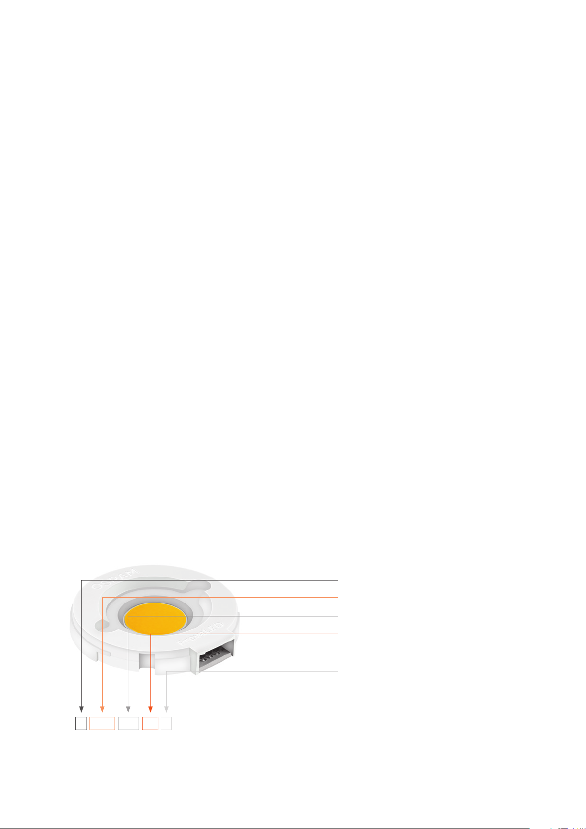
2.1 Light distribution
The light distribution of the LED module is shown in the
graph below. PrevaLED
®
Core Z3 LED modules create
a beam angle of 115° FWHM (full width at half maximum).
C 0°
75°
60°
45°
30°
15°
2.2 Refl ector design
High luminous intensities (1.5–4.5 Mcd/m2) are the key
factor for LED-based lamps and luminaires in the area of
refl ector applications such as spotlights. For this purpose,
light sources with small light-emitting surfaces and a high
luminous fl ux – as realized in the PrevaLED
®
Core Z3 – are
required, because in such combinations, the light can be
collimated especially well with refl ectors.
®
The PrevaLED
Core Z3 is equipped with a surface that
emits light evenly and makes the use of diffuser materials
unnecessary due to its high level of homogeneity. The
minimized light-emitting surface (LES) and a positioning of
the refl ector close to the LES allows for an improved optical
handling. Generally, the properties of the PrevaLED
®
Core Z3
help to avoid roughness and facets, allowing for very small
total beam angles of 10° or less.
OSRAM provides mechanical (3D fi les) and optical simulation data (ray fi les) to support customized refl ector
designs. Mechanical fi les can be downloaded at
www.osram.com/prevaled.
Ray fi le data are available upon request through your
sales partner. Available ray fi le formats are ASAP, SPEOS,
LightTools and Photopia (all bi nary).
4
Page 5

PrevaLED® Core Z3 LED modules | Optical considerations
PrevaLED® Core Z3, 1100 lm, LES 9, OCA A*
Reflector output diameter [mm]
Reflector
height [mm]
50 12°; 14000 cd;
40 14°; 10000 cd;
30 15°; 9000 cd;
20 18°; 5000 cd;
PrevaLED® Core Z3, 2000 lm, LES 19, OCA C*
Reflector
height [mm]
100 15°; 17000 cd;
80 15°; 16000 cd;
60 19°; 10000 cd;
40 19°; 8000 cd;
PrevaLED® Core Z3, 3000 lm, LES 19, OCA C*
40 50 60 70
89 %; 3400 lx;
12.5 cd/lm
12°; 13000 cd;
89 %; 2400 lx;
8.7 cd/lm
91 %; 2100 lx;
7.8 cd/lm
14°; 7000 cd;
93 %; 1300 lx;
4.7 cd/lm
Reflector output diameter [mm]
80 100 120 140
90 %; 2600 lx;
5.2 cd/lm
93 %; 2100 lx;
4.2 cd/lm
95 %; 1700 lx;
6.0 cd/lm
88 %; 4200 lx;
8.4 cd/lm
89 %; 3900 lx;
7.9 cd/lm
15°; 14000 cd;
91 %; 3500 lx;
7.0 cd/lm
14°; 11000 cd;
95 %; 2600 lx;
5.3 cd/lm
91 %; 3200 lx;
11.5 cd/lm
12°; 11000 cd;
93 %; 2700 lx;
9.9 cd/lm
11°; 7000 cd;
96 %; 1800 lx;
6.6 cd/lm
12°; 22000 cd;
89 %; 5600 lx;
11.2 cd/lm
12°; 21000 cd;
91 %; 5200 lx;
10.4 cd/lm
12°; 18000 cd;
93 %; 4400 lx;
8.9 cd/lm
11°; 12000 cd;
96 %; 3100 lx;
6.1 cd/lm
10°; 17000 cd;
90 %; 4400 lx;
15.9 cd/lm
10°; 15000 cd;
92 %; 3900 lx;
14.0 cd/lm
9°; 13000 cd;
94 %; 3100 lx;
11.4 cd/lm
9°; 7000 cd;
97 %; 1800 lx;
6.4 cd/lm
11°; 28000 cd;
90 %; 7100 lx;
14.3 cd/lm
10°; 25000 cd;
92 %; 6400 lx;
12.8 cd/lm
10°; 21000 cd;
94 %; 5200 lx;
10.5 cd/lm
8°; 13000 cd;
97 %; 3300 lx;
6.5 cd/lm
PrevaLED® Core Z3, 5000 lm, LES 23, OCA D*
Reflector output diameter [mm]
Reflector
height [mm]
100 14°; 38000 cd;
80 18°; 27000 cd;
60 18°; 24000 cd;
40 22°; 14000 cd;
*Parabolic refl ector, 85% specular refl ectance, lux in 2 m distance
80 100 120 140
12°; 48000 cd;
84 %; 3600 lx;
2.9 cd/lm
81 %; 6700 lx;
5.3 cd/lm
83 %; 6000 lx;
4.8 cd/lm
16°; 18000 cd;
85 %; 4600 lx;
3.6 cd/lm
80 %; 9500 lx;
7.6 cd/lm
15°; 35000 cd;
82 %; 8900 lx;
7.1 cd/lm
14°; 30000 cd;
84 %; 7500 lx;
6.0 cd/lm
12°; 21000 cd;
87 %; 5300 lx;
4.2 cd/lm
81 %; 12100 lx;
9.7 cd/lm
12°; 43000 cd;
83 %; 10900 lx;
8.7 cd/lm
11°; 36000 cd;
85 %; 8900 lx;
7.1 cd/lm
10°; 22000 cd;
88 %; 5600 lx;
4.5 cd/lm
— A parabolic refl ector shape is used.
— A fi ne facet structure is applied as it should always
be used for CoB LEDs. The impact on the narrowest
possible beam angle is small.
— A purly specular refl ectance of 85 % is assumed.
— The collimation strength values cd/lm refer to the
LED module fl ux.
— Data values in red correspond to a refl ector with an
extremely large diameter/height ratio D/H > 2 (cut-off
angle > 45°). This is not recommended with respect
to glare.
— Illuminance values are the maximum values in the spot
center in 2 m distance to the refl ector.
The PrevaLED® Core Z3 can be used with secondary optics.
Zhaga-compliant off-the-shelf solutions can be used with the
LED module. For optics support, you can fi nd suppliers via
OSRAM's LED Light for You network: www.ledlightforyou.com.
Moreover, off-the-shelf solutions and support for refl ector
design are available, e.g., from the following suppliers:
Reflector output diameter [mm]
Reflector
height [mm]
100 15°; 25000 cd;
80 15°; 24000 cd;
60 19°; 16000 cd;
40 19°; 13000 cd;
80 100 120 140
88 %; 6300 lx;
8.4 cd/lm
89 %; 5900 lx;
7.9 cd/lm
15°; 21000 cd;
90 %; 3900 lx;
5.2 cd/lm
93 %; 3100 lx;
4.2 cd/lm
91 %; 5200 lx;
7.0 cd/lm
14°; 16000 cd;
95 %; 4000 lx;
5.3 cd/lm
12°; 34000 cd;
89 %; 8400 lx;
11.2 cd/lm
12°; 31000 cd;
91 %; 7800 lx;
10.4 cd/lm
12°; 27000 cd;
93 %; 6600 lx;
8.9 cd/lm
11°; 18000 cd;
96 %; 4600 lx;
6.1 cd/lm
11°; 43000 cd;
90 %; 10700 lx;
14.3 cd/lm
10°; 38000 cd;
92 %; 9600 lx;
12.8 cd/lm
10°; 32000 cd;
94 %; 7900 lx;
10.5 cd/lm
8°; 20000 cd;
97 %; 4900 lx;
6.5 cd/lm
Jordan Refl ektoren GmbH & Co. KG
Schwelmer Strasse 161
42389 Wuppertal, Germany
+49 202 60720
info@jordan-refl ektoren.de
www.jordan-refl ektoren.de
ACL-Lichttechnik GmbH
Hans-Boeckler-Strasse 38 A
40764 Langenfeld, Germany
+49 2173 9753 0
info@refl ektor.com
www.refl ektor.com
5
Page 6
PrevaLED® Core Z3 LED modules | Optical considerations
Alux·Luxar GmbH & Co. KG
Schneiderstrasse 76
40764 Langenfeld, Germany
+49 2173 279 0
sales@alux-luxar.de
www.alux-luxar.de
Almeco S.p.A.
Via della Liberazione, 15
20098 San Giuliano, Milanese (Mi), Italy
+39 02 988963 1
info.it@almecogroup.com
www.almecogroup.com
Nata Lighting Co., Ltd.
380 Jinou Road, Gaoxin Zone
Jiangmen City, Guangdong, China
+86 750 377 0000
info@nata.cn
www.nata.cn
®
PrevaLED
Core Z3 3D fi les including the bayonet base for
design-in are available at:
www.osram.de/prevaled-core.
2.4 Color temperature
The PrevaLED® Core Z3 series is currently available in 2 700
K, 3 000 K, 3 500 K and 4 000 K. The color coordinates
within the CIE 1931 color space are given below.
2700 K 3000 K 3500 K 4000 K
Cx 0.4585 0.4345 0.4083 0.3828
Cy 0.4104 0.4033 0.3921 0.3803
®
Within each available color temperature, the PrevaLED
Core Z3 series provides a maximum color variation of three
threshold value units (MacAdam steps). The following diagram shows these threshold values within the CIE 1931
color space.
2.3 Refl ector mounting
The LED modules have a clearly defi ned optical contact
area (OCA), which provides a defi ned surface for attaching
the refl ector. In this confi guration, the mounting and mechanical support of the refl ector must be ensured by the luminaire body or by suitable structures for refl ector mounting.
The following has to be considered when mounting the refl ector: Due to the creepage and clearance distances specifi ed in the norm (IEC 61347-1/U935, among others), it is recommended to stay within the OCA values of the corresponding category (see PrevaLED
®
datasheet).
Additionally, a bayonet base option is provided, with the
help of which the refl ector can be attached directly to the
PrevaLED
®
Core Z3.
y
0.45
0.40
0.35
6000
0.35
3000
4000
0.40 0.45 0.50
2500
2000
x
Allowed compression: 20 N
Allowed tension: 20 N
Allowed torque: 1 Nm
6
Page 7

PrevaLED® Core Z3 LED modules | Optical considerations
2.5 Color rendering
PrevaLED® Core Z3 LED modules provide a color rendering
index (CRI) of either > 80 or >90. The table below shows the
individual R
values from R1 to R16 for the available color
a
temperatures.
R
R1 R2 R3 R4 R5 R6 R7 R8 R9 R10 R11 R12 R13 R14 R15 R16
a
2700 83 83 95 93 78 82 93 82 61 18 87 76 74 86 97 76 73
3000 85 85 96 93 80 85 93 83 65 26 89 78 73 88 97 80 77
3500 87 87 97 94 81 86 94 84 70 33 92 80 69 91 97 83 78
4000 88 89 99 93 82 88 93 84 73 41 95 81 67 93 97 86 79
3000 94 96 99 98 92 94 96 91 87 74 97 93 78 97 99 93 90
2.6 Spectral distribution
The typical spectral distribution of the PrevaLED® Core Z3
LED modules is shown in the following diagram.
Relative luminous intensity [%]
120
100
80
60
40
20
0
400
Values measured at tc = 25 °C
450 500 550
827 830 835 840 930
600 650 700 750
Wavelength [nm]
7
Page 8

PrevaLED® Core Z3 LED modules | Optical considerations
2.7 Flux behavior
The following diagrams show the luminous fl ux over
the operating current for all PrevaLED
®
Core Z3 modules.
PL-CORE-1100-8xx-Z3
PhiV typ [lm]
140 0
120 0
1000
800
600
400
100 150
PL-CORE-3000-XXX-Z3
PhiV typ [lm]
Z3 1100 lm 840 65 °C Z3 1100 lm 830 65 °C
200 250 300 350
I [mA]
Z3 3000 lm 840 65 °C Z3 3000 lm 830 65 °C
Z3 3000 lm 930 65 °C
PL-CORE-2000-XXX-Z3
PhiV typ [lm]
3000
2500
2000
150 0
1000
500
200 250 400 450350
PL-CORE-5000-XXX-Z3
PhiV typ [lm]
Z3 2000 lm 840 65 °C Z3 2000 lm 830 65 °C
Z3 2000 lm 930 65 °C
300 500 550 600
I [mA]
Z3 5000 lm 840 65 °C Z3 5000 lm 830 65 °C
Z3 5000 lm 930 65 °C
5000
4000
3000
2000
6000
5000
4000
3000
2000
1000
0
700 900 1000 1100500 600
800
I [mA]
0200
400 1200 1400 1600
800 1000600
I [mA]
8
Page 9

PrevaLED® Core Z3 LED modules | Electrical considerations
3 Electrical considerations
3.1 Forward voltage as a function of temperature
Relative forward voltage normalized at 65 °C [%]
101.5
101.0
100.5
100.0
99.5
99.0
98.5
98.0
020406080100120
110 0 l m 2000 lm 3000 lm 5000 lm
Case temperature tc [°C]
3.2 Electronic control gear/LED module combination
PrevaLED® Core Z3 LED modules can either be used with
constant-current control gears or in combination with
OSRAM OTi control gears. The OTi control gears provide a
thermal shutdown function as well as an automatic fl ux calibration. Constant- current control gears do not provide these
features. The table below shows possible combinations of
PrevaLED
®
Core Z3 LED modules and OSRAM ECGs.
Modules Drivers
Typ. current
[mA]
PL-CORE-1100-830 235
PL-CORE-1100-840 220 1210
PL-CORE-2000-830 400 2070
PL-CORE-2000-840 385 2160
PL-CORE-2000-930 490 1750 TBD
PL-CORE-3000-830 590 3035
PL-CORE-3000-840 575 3115
PL-CORE-3000-930 730 2900 2900 2900 3240 2900
PL-CORE-5000-830 950 3400 3400 TBD
PL-CORE-5000-840 885 3700 3700 TBD
PL-CORE-5000-930 1155
2300: System fi t OK nominatyp. fl ux level (lm) if deviating from nominal
: System fit OK for 1 or more current settings
Preliminary data. The fl ux levels realized with fi xed-value constant-current OTe and OT FIT drivers will change as the effi cacy of the modules evolves.
OT 35/45
LTCS
OT 45
DALI LTCS
OTe
25/CS
OTe
35/CS
OTe
50/CS
OTe 50/CS
FAN
4600 4600
OT FIT
15/CS
1160
OT FIT
25/CS
OT FIT
OTi DALI 25OTi DALI 35OTi DALI
35/CS
50 FAN
9
Page 10

PrevaLED® Core Z3 LED modules | Electrical considerations
3.3 Wiring
The input clamps used in the PrevaLED® Core Z3 can handle solid wires with a cross-section of 0.5–1.0 mm
2
(AWG 21-17).
Example: H05V-U 1x 0.5 mm2
Wire preparation
For wires with
2
(AWG17):
1 mm
5.5 mm
For wires with
0.5-0.823 mm2
(AWG21–18):
5.3 +- 0.2 mm
Please note:
— The connector is designed for three “poke-in” and
release cycles.
— The installation of LED modules needs to be carried out
in compliance with all applicable electrical and safety
standards. Only qualifi ed personnel should be allowed to
perform installations.
— If you cannot use solid wires, you can use stranded wires
with a diameter of 0.5 to 0.75 mm and tin-coat the wire
ends before inserting them into the connection clamp.
10
Page 11

PrevaLED® Core Z3 LED modules | Electrical considerations
Connect and release
Connect
Plug wire directly
Release
1 2
Use a very slim screwdriver and push gently into the release hole
Note: Push in the screwdriver below the release spring.
3
Pull out the wire and afterwards the screwdriver
11
Page 12

PrevaLED® Core Z3 LED modules | Electrical considerations
3.4 OTi electronic control gear series
If you use the PrevaLED® Core Z3 series in combination with
the OSRAM OTi control gear series, you will get the best
results and the full functionality of the LED module.
The system includes a one-wire communication interface,
using the LEDset II communication standard between the
control gear and the module. A thermal derating and a fl ux
calibration are included.
Therefore, please connect all three terminals of the module
to the control gear:
3.6 OTe electronic control gear series
If you like to use the OSRAM OTe series, please connect the
terminal LED+ to the module and select the desired current
by connecting it to only one of the output terminals 21, 22
or 23.
Select only
1 connection
terminal
3.7 OT LCTS electronic control gear – LEDset GEN 1
If you want to use PrevaLED® Core Z3 LED modules with
LCTS control gears, you need to attach a resistor to the
ECG to adjust the needed current.
3.5 OT FIT electronic control gear series
It is also possible to use the PrevaLED® Core Z3 series with
a constant-current driver. The OT FIT series offers different
available currents. To wire the module to the ECG, please
connect the ports LED+ and LED- to the module as shown
in the image below. The current is selected by a bridge
between ports 3, 4 and 5:
OT 35/220-240/700 LCTS
You can calculate the resistor using the formula:
I
out
R
1 + 9
=
set
I
set
= The value of the resistor in Ohm
R
set
= The output current desired to operate
I
out
I
[V]
nom
the LED module
= 700 mA for OT 35/700 LCTS and
I
nom
OT DALI 45/700 LCTS
= 274 μA
I
set
12
Page 13

PrevaLED® Core Z3 LED modules | Electrical considerations
The following values result for the modules which are
possible to drive with LCTS drivers:
Module I [mA] R [Ohm]
PL-CORE-2000-830 400 22419
PL-CORE-2000-840 385 21715
PL-CORE-2000-930 490 26642
PL-CORE-3000-830 590 31335
PL-CORE-3000-840 575 30631
PL-CORE-3000-930 730 Use DIP switch for 700 mA. Module is under-driven.
PL-CORE-5000-830 950 Use DIP switch for 700 mA. Module is under-driven.
PL-CORE-5000-840 885 Use DIP switch for 700 mA. Module is under-driven.
The resistor has to be placed between Vset and GNDset:
Example of wiring:
For further information on the LEDset interface, please refer
to the LEDset application note at www.osram.com.
3.8 Maximum allowed number of control gears
per circuit breaker
Please note:
To activate the LEDset interface, both DIP switches of the
LED module have to be in the “OFF” position.
DIP1 DIP2 Current
Off Off LEDset
Off On 700 mA
On Off 500 mA
On On 350 mA
B16 B10
OTe 35/700 50 30
OT 35/LCTS 84 52
OT 45 LCTS 60 40
OT 45 DALI LCTS 47 18
OTe 25/CS 50 30
OTe 35/CS S 44 28
OTe 35/CS 25 15
OTe 50/1A4 CS 25 15
OTe 50/1A0 CS 25 15
OTe 50/CS FAN 25 15
OT FIT 15CS 28 17
OT FIT 25/CS 28 17
OT FIT 35/CS 28 17
OTi DALI 25 84* 52*
OTi DALI 35 60* 40*
OTi DALI 50 FAN 13 18
* Preliminary data
3.9 ESD
It is not necessary to handle PrevaLED® Core Z3 LED
modules in electrostatic protected areas (EPAs). To protect
a PrevaLED
®
Core LED module from electrostatic damage,
do not open it. The LED module fulfi lls the requirement of
the immunity standard IEC/EN 61547.
13
Page 14

PrevaLED® Core Z3 LED modules | Thermal considerations
4 Thermal considerations
The proper thermal design of an LED luminaire is critical for
achieving the best performance and ensuring the longest
lifetime of all components. Due to the high effi cacy of Pre-
®
Core Z3 LED modules, only a partial amount of the
vaLED
introduced electrical power has to be dissipated through the
back of the LED module. The thermal power that has to be
dissipated for PrevaLED
®
Core Z3 LED modules is given
below.
4.1 Thermal power values
Max. thermal
Typ. thermal
Product
PL-CORE-1100-830-Z3 7.7 8.2 4.91
PL-CORE-1100-840-Z3 6.9 7.3 5.48
PL-CORE-2000-830-Z3 11.2 12.4 3.23
PL-CORE-2000-930-Z3 14.4 15.6 2.56
PL-CORE-2000-840-Z3 10.1 11.0 3.63
PL-CORE-3000-830-Z3 15.9 17.4 2.30
PL-CORE-3000-930-Z3 21.2 23.3 1.72
PL-CORE-3000-840-Z3 15.1 16.6 2.41
PL-CORE-5000-830-Z3 28.6 31.3 1.28
PL-CORE-5000-930-Z3 33.7 36.8 1.09
PL-CORE-5000-840-Z3 25.1 27.4 1.46
1) Value measured at the t
2) Value measured at the rear of the luminaire at an ambient temperature
of 25 °C.
power [W]
point at a reference temperature (tr) of 65 °C.
c
power [W] at
1)
nominal current1)
Max. allowable
thermal resis-
tance Rth [K/W]
2)
4.2 TIM and other accessories
When mounting a PrevaLED® Core Z3 LED module within a
luminaire, it is recommended to use thermal interface
material (TIM) between the back of the LED module and the
luminaire housing or heat sink. It is recommended to use
thermal paste, but thermal foil can also be used. In order to
balance possible unevenness, the material should be
applied as thinly as possible, but as thickly as necessary.
In this way, air inclusions, which may otherwise occur, are
replaced by TIM and the required heat conduction between
the back of the LED module and the contact surfaces of the
luminaire housing is achieved. For this purpose, the planarity
and smoothness of the surface should be optimized.
The list below is a selection of suppliers of thermal interface
materials. Additional suppliers for thermal management
support can also be found via OSRAM’s LED Light for your
network: www.ledlightforyou.com.
Thermal interface materials
Alfatec www.alfatec.de
Kerafol www.kerafol.de
Laird www.lairdtech.com
Bergquist www.bergquistcompany.com
Arctic Silver www.arcticsilver.com
Wakefield www.wakefield.com
To achieve the best possible lifetime of the module and to
save it from damage by overheating, a thermal protection
feature is added. This feature is only usable when operating
the module with an OSRAM OTi control gear.
The characteristics of the thermal protection are shown in
the following diagram:
Current [% of minimal ECG current]
100
50
0
75 105
tc [°C]
The behaviour below 50 % of the system current depends on the
nominal system current and the applied ECG.
4.3 Cooling system and heat sinks
For the selection of a suitable heat sink, several points
regarding thermal resistance have to be considered.
The selection is usually done through the following
necessary steps.
Total power dissipation of the
Defi ne boundary
conditions
Estimate heat sink
thermal resistance on
LED module level
Select heat sink
thermal resistance
Selection of a heat sink
LED module, max. ambient
temperature t
temperature t
time requirements
Rth =
tr measured at the tc point
Use the estimated Rth as a target for a possible heat sink
profi le and examine the performance curve in the heat sink
manufacturer’s catalog.
, max. reference
a
according to life-
r
t
- t
r
a
P
th
14
Page 15

PrevaLED® Core Z3 LED modules | Thermal considerations
Please note:
A thermal design must always be confi rmed by performing
a thermal measurement in steady-state condition.The whole
area of the PCB must be in contact with solid material of the
heat sink. In the following, you fi nd two examples of how to
cool a PrevaLED
®
Core Z3 LED module.
Example 1:
LED module: PL-CORE 1100-827
Heat sink: Fischer SK572 height: 37.5 mm
TIM: Kerafoil 86/82
: 25 °C
T
ambient
Temperature at the t
point: 61 °C
c
Example 2:
LED module: PL-CORE 5000-830
Heat sink: Sunon LA003-012A82DY
(active cooling solution with 12-V fan)
TIM: Kerafoil 86/82
: 25 °C
T
ambient
Temperature at the t
point: 57 °C
c
Please note that the shown solutions are just examples. A
thermal system always depends on many factors, such as
airfl ow, ambient temperature etc. Please check your entire
cooling system by performing a thermal measurement in
steady-state condition. The list below is a selection of suppliers of different cooling solutions.
Location of the tc point
tc point
2D code
To ensure a lifetime of 50000 hours (L
temperature (t
) at the tc point must not exceed 65 °C. The
r
maximum temperature reached at the t
), the reference
70B50
point must not
c
exceed 85 °C. A correct temperature measurement can,
for example, be performed with a thermocouple.
4.5 Thermocouple
Use a thermocouple that can be glued onto the LED module.
Make sure that the thermocouple is fi xed with direct contact
to the t
point. Examples of suitable thermo couples:
c
Cooling systems
Nuventix www.nuventix.com
Sunon www.sunoneurope.com
Cooler Master www.coolermaster.com
AVC www.avc-europa.de
SEPA www.sepa-europe.com
Fischer Elektronik www.fischerelektronik.de
Meccal www.meccal.com
Wakefield www.wakefield.com
R-Theta www.r-theta.com
Cool Innovations www.coolinnovations.com
K-type thermocouple with miniature connector
Different thermocouples
Illustration Description Temperature range [°C]
4.4 Tc point location and temperature measurement
The tc point is the location to check if the chosen cooling
solution (heat sink and TIM) is suffi cient to ensure the LED
module performance. The t
point is located on the back of
c
the LED module under the center of the diffuser (see image
below).
PVC-insulated
thermo couple
PFA-insulated
thermo couple
Sprung
thermo couple
-10 … +105
-75 … +260
-75 … +260
15
Page 16

PrevaLED® Core Z3 LED modules | Thermal considerations
To measure the temperature and to ensure a good thermal
coupling between the LED module and the heat sink, drill a
hole into the heat sink and push the thermocouple through
the heat sink. To ensure a direct contact between the thermocouple and the PCB, it is recommended to glue the thermocouple onto the PCB. You can, for example, use an acrylic adhesive (e.g. type Loctite 3751).
It is also possible to use a sprung thermocouple. A suitable
type is: Electronic Sensor FS TE-4-KK06/09/2m. Please note that a good thermal contact between the thermocouple
and the PCB is required. Please refer to the data sheet and
the application guideline of the manufacturer to ensure correct handling.
Note: Please keep in mind that you need a direct contact
between the thermocouple and the PCB.
Note: If you use a TIM, please cut out a small area where
the thermocouple has direct contact to the metal-core
PCB.
Another possible way is to create a small groove along the
top surface of the heat sink and run the thermocouple inside
the groove to the t
point.
c
16
Page 17

PrevaLED® Core Z3 LED modules | Lifetime and thermal behavior
5 Lifetime and thermal behavior
5.1 Flux as a function of temperature
The following diagram shows the behavior of the fl ux output
over the t
PL-CORE-2000 lm/3000 lm-Z3
Relative luminous intensity normalized at 65 °C [%]
108
106
104
102
100
98
point temperature for Prevaled Core Z3.
c
96
94
92
25 45 65 85
Case temperature tc [°C]
5.2 Lifetime
OSRAM PrevaLED® Core Z3 modules have a lifetime of
50 000 hours (L
) at a tc point temperature of 65 °C. This
70B50
means that after 50 000 hours, over 50 % of the used modules will have more than 70 % of the initial luminous fl ux. If you
operate the module at a lower t
point temperature, the life-
c
time of the module is going to rise signifi cantly.
Note: Higher t
PrevaLED
temperatures lead to a shorter lifetime of the
c
®
Core Z3 LED modules. Moreover, the failure rate
will also increase.
17
Page 18

PrevaLED® Core Z3 LED modules | Mechanical considerations
Enable 3D View
6 Mechanical considerations
The following schematic drawing provides further details on
the dimensions of PrevaLED
fi les of the LED modules, please go to: www.osram.com.
6.1 Outline drawing
1100 lm
®
Core Z3 LED modules. For 3D
2000/3000 lm
6.3 Mechanical protection of the PrevaLED® Core Z3
LED module
The housing of a PrevaLED® Core Z3 LED module should
not be exposed to strong mechanical stress. Please apply
force only to the dedicated mounting positions. Strong mechanical stress can lead to irreversible damage of
the LED module.
Note: Please do not touch or mechanically stress
the yellow chip-on-board surface. This could damage
the module.
For operation in damp, wet or dusty environments, the user
has to make sure that an adequate ingress protection is
chosen. The LED module has to be protected by a suitable
IP classifi cation of the luminaire housing. Please con sider
the luminaire standard IEC 60598-1 as well as the different
requirements.
5000 lm
6.2 3D drawing
6.4 Mounting
To fi x a PrevaLED® Core Z3 LED module to a heat sink, you
can use M3 cylinder head screws according to DIN 7984. If
you cannot use DIN screws, please use the following specifi cation: Height of head not more than 2.6 mm, diameter of
head below 5.5 mm. The allowed torque is0.4 to 0.6 Nm.
18
Page 19

PrevaLED® Core Z3 LED modules | Norms and standards
7 Norms and standards
Safety: IEC/EN 62031
IEC/EN 60598-1
Photobiological safety: IEC/EN 62471
Risk group: 1
Electromagnetic compatibility: CISPR 15
IEC/EN 61547
IEC/EN 61000-3-2
IEC/EN 61000-3-3
EN 55015
Ingress protection: IP10
Flammability of plastics: UL8750 Class 2/UL 94 850 °C glow wire test
Approvals: CE,UL
19
Page 20

www.osram.com/prevaled-core
OSRAM GmbH
Head Offi ce:
Marcel-Breuer-Strasse 6
80807 Munich, Germany
Phone +49 (0)89-6213-0
Fax +49 (0)89-6213-20 20
www.osram.com
12/13 OSRAM S-GI MK EM Subject to change without notice. Errors and omissions excepted.
 Loading...