

Page 1
www.osram.dewww.osram.
de
www.osram.com/prevaled-core
Technical application guide
®
PrevaLED
Core Z2 light engines
JUNE
2013
Page 2

CONTENTS
CONTENTS
1. Introduction 3
1.1. System overview 3
1.2. System information 6
1.2.1. Nomenclature and marking 6
1.2.2. Technical data 7
1.2.3. Accessories 7
1.3. Zhaga – interchangeability of light engines 7
2. Optical considerations 8
2.1. Refl ector 8
2.1.1. Refl ector design 9
2.1.2. Refl ector mounting 10
2.1.3. Lighting design information 10
2.2. Luminous fl ux and color stability 11
2.3. Zhaga – optical interface 11
3. Electrical considerations 12
3.1. Safety requirements 12
3.2. Wiring information 12
3.3. Wiring in class I and class II luminaires 13
3.4. Optional cable clamp 13
3.5. Electrostatic safety measures 14
3.6. Inrush current limitation 14
3.7. Connection information 14
3.8. Zhaga – electrical interface 14
4. Thermal considerations 15
4.1. Thermal interface material and other accessories 15
4.2. Heat sink 16
4.3. Temperature measurement 17
4.4. Thermal simulation 18
4.5. ECG thermal considerations 19
4.6. Thermal management and lifetime 19
4.7. Zhaga – thermal interface 19
5. Mechanical considerations 21
5.1. LED module dimensions 21
5.2. Mechanical protection of the LED module 21
5.3. ECG dimensions 22
5.4. LED module attachment 22
5.5. Zhaga – mechanical interface 22
6. Assembly in a reference luminaire 23
6.1. Preparation 23
6.2. Wiring and refl ector/cover 24
6.3. Commissioning the PrevaLED
7. Norms and standards 25
7.1. Norms and standards for PrevaLED® LED modules and light engines 25
7.2. Norms and standards for control gears 25
7.3. Photobiological safety 26
®
light engine 24
Please note:
All information in this guide has been prepared with great care.
OSRAM, however, does not accept liability for possible errors,
changes and/or omissions.
Please check www.osram.com/prevaled-core or contact your
sales partner for an updated copy of this guide.
2
Page 3

INTRODUCTION
1. Introduction
1.1. System overview
Brightness levels of today’s LEDs are opening the door for
usage of LEDs in general lighting applications requiring
high lumen output levels. Building an LED-based luminaire
poses a new set of technical challenges, among them new
optical requirements, providing adequate thermal management for stable operation and lastly dealing with the everimproving performance of LEDs.
®
OSRAM’s PrevaLED
family of LED light engines addresses
the challenges of LED-based lighting while at the same
time giving the user great performance and fl exibility.
®
The PrevaLED
Core Z2 series of light engines is ideally
suited for use in refl ector-based, rotation-symmetric
applications such as downlights or spotlights. These light
engines provide several convincing benefi ts in the
application:
®
• PrevaLED
Core Z2 light engines are available as a system of matching LED modules and ECGs and deliver
maximum performance at very high levels of effi ciency.
• These light engines provide superior optical performance, both in terms of their optical effi ciency as well
as their high quality of light (color rendering).
• A wide range of lumen packages (currently available
from 800–5000 lm) allows addressing a wide range of
applications based on a single platform. This platform
allows, for example, the operation of a sequence of
spotlights – ranging from halogen-class up to HID levels
– in a row, while at the same time creating a homogeneous overall impression for the end user.
• Thanks to their high thermal and optical performance,
luminaires based on PrevaLED
®
Core Z2 light engines
can be realized with minimized size of required heat sink
and refl ector, giving the user greater design fl exibility.
• PrevaLED
®
Core Z2 light engines provide standardized
interfaces for the user, in particular by defi ning stable
lumen packages over time. Independent of future increases in LED effi cacy, the luminous fl ux of an individual
LED module will remain constant, but at lower power
consumption. In this way, a luminaire designed on the
PrevaLED
®
Core platform will automatically benefi t from
effi cacy improvements without needing a lengthy and
costly redesign of the base construction.
3
Page 4
INTRODUCTION
At present, PrevaLED® Core Z2 light engines are available
as systems in different performance grades:
• Lumen packages of 800–5000 lm are available with a
good to very good color rendering (with typ. CRI 83
and typ. CRI 93).
• The lumen packages of 800–5000 lm with CRI 83 are
especially well suited for consumer applications.
Movable 3D PrevaLED® Core Z2
(works with Adobe Acrobat 7 or higher)
The high efficacy of the light engines not only results in
minimized energy consumption of the luminaire, but also
reduces the thermal load on the luminaire, allowing for
smaller and lighter designs of the heat sink.
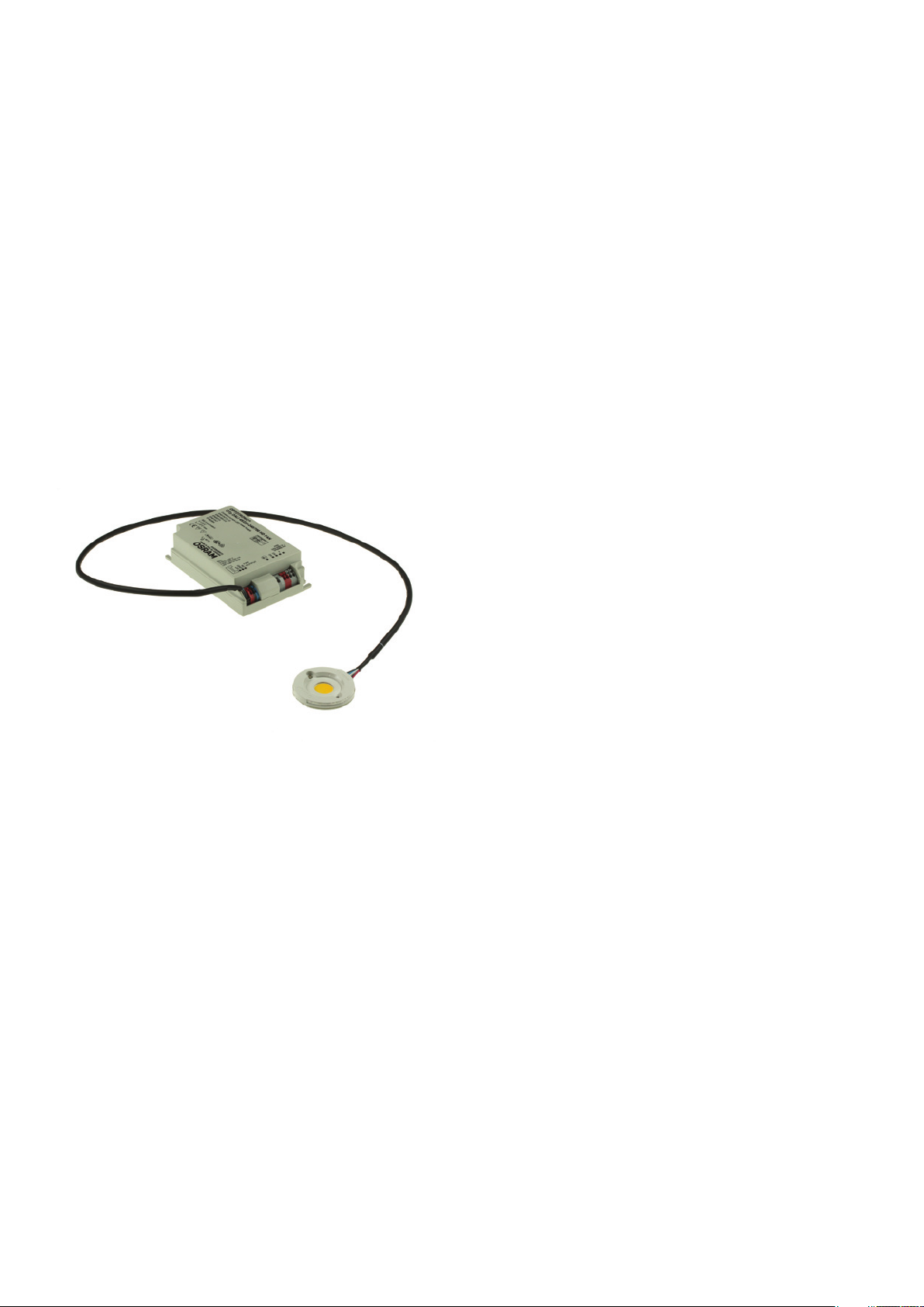
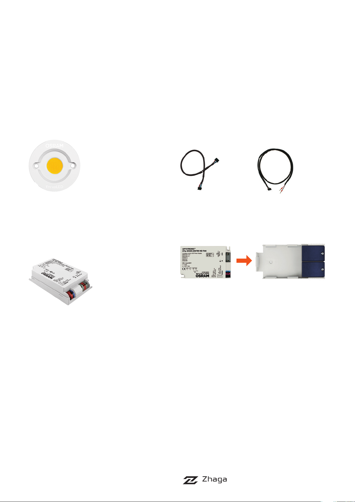
The PrevaLED® light engine consists of an LED module,
dedicated OTp and connection cable.
Both the CRI 90 and the CRI 80 types are available with
2700 K, 3000 K, 3500 K and 4500 K CCT; in lumen
packages of 800, 1500, 2000, 3000, 4000 and 5000 lm.
®
PrevaLED
OPTOTRONIC
Core LED modules must be operated with
®
power supplies of the “OTp” type. Available
types are detailed in the next section. All possible system
configurations are listed on the latest datasheet.
Additional details on optical, thermal, mechanical and
electrical characteristics can be found in the following
sections. Additional and updated information (as well as
updates of this guide) will be posted at www.osram.com/
prevaled-core.
OSRAM also provides an extensive range of energy-saving
light management components, such as sensors and room
controllers. By use of these products, additional energy sa vings can be realized. For an overview of these products,
please visit www.osram.com/lms.
4
Page 5
INTRODUCTION
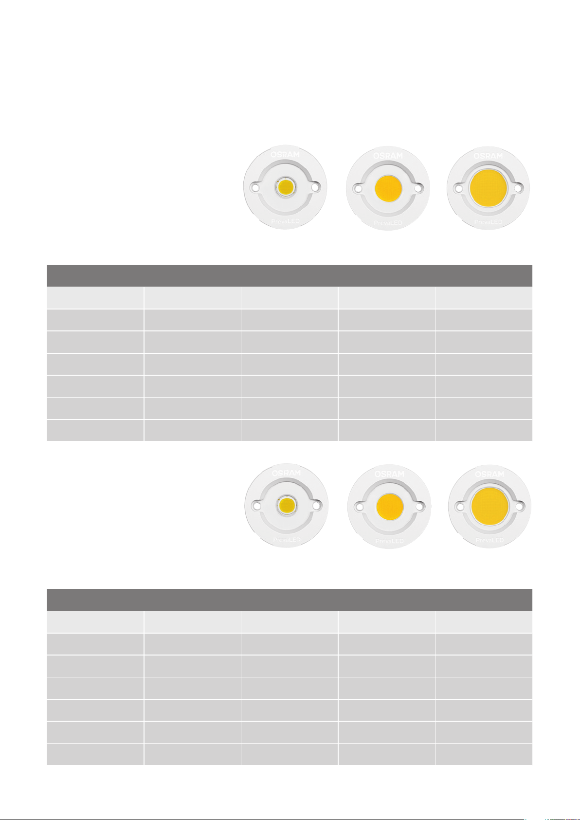
PrevaLED® Core Z2 –
CRI 90: Six lumen packages
800 lm, 1500 lm
2000 lm
3000 lm, 4000 lm, 5000 lm
PrevaLED® Core Z2 – CRI 90: Six lumen packages
2700 K 3000 K 3500 K 4000 K
800 lm LEP-800-927-C-Z2 LEP-800-930-C-Z2 LEP-800-935-C-Z2 LEP-800-940-C-Z2
1500 lm LEP-1500-927-C-Z2 LEP-1500-930-C-Z2 LEP-1500-935-C-Z2 LEP-1500-940-C-Z2
2000 lm LEP-2000-927-C-Z2 LEP-2000-930-C-Z2 LEP-2000-935-C-Z2 LEP-2000-940-C-Z2
3000 lm LEP-3000-927-C-Z2 LEP-3000-930-C-Z2 LEP-3000-935-C-Z2 LEP-3000-940-C-Z2
4000 lm LEP-4000-927-C-Z2 LEP-4000-930-C-Z2 LEP-4000-935-C-Z2 LEP-4000-940-C-Z2
5000 lm – LEP-5000-930-C-Z2 LEP-5000-935-C-Z2 LEP-5000-940-C-Z2
®
PrevaLED
Core Z2 –
CRI 80: Six lumen packages
800 lm, 1500 lm
2000 lm
(2000 lm), 3000 lm,
4000 lm, 5000 lm
PrevaLED® Core Z2 – CRI 80: Six lumen packages
2700 K 3000 K 3500 K 4000 K
800 lm LEP-800-827-C-Z2 LEP-800-830-C-Z2 LEP-800-835-C-Z2 LEP-800-840-C-Z2
1500 lm LEP-1500-827-C-Z2 LEP-1500-830-C-Z2 LEP-1500-835-C-Z2 LEP-1500-840-C-Z2
2000 lm LEP-2000-827-C-Z2 LEP-2000-830-C-Z2 LEP-2000-835-C-Z2 LEP-2000-840-C-Z2
3000 lm LEP-3000-827-C-Z2 LEP-3000-830-C-Z2 LEP-3000-835-C-Z2 LEP-3000-840-C-Z2
4000 lm LEP-4000-827-C-Z2 LEP-4000-830-C-Z2 LEP-4000-835-C-Z2 LEP-4000-840-C-Z2
5000 lm – LEP-5000-830-C-Z2 LEP-5000-835-C-Z2 LEP-5000-840-C-Z2
5
Page 6
INTRODUCTION
1.2. System information
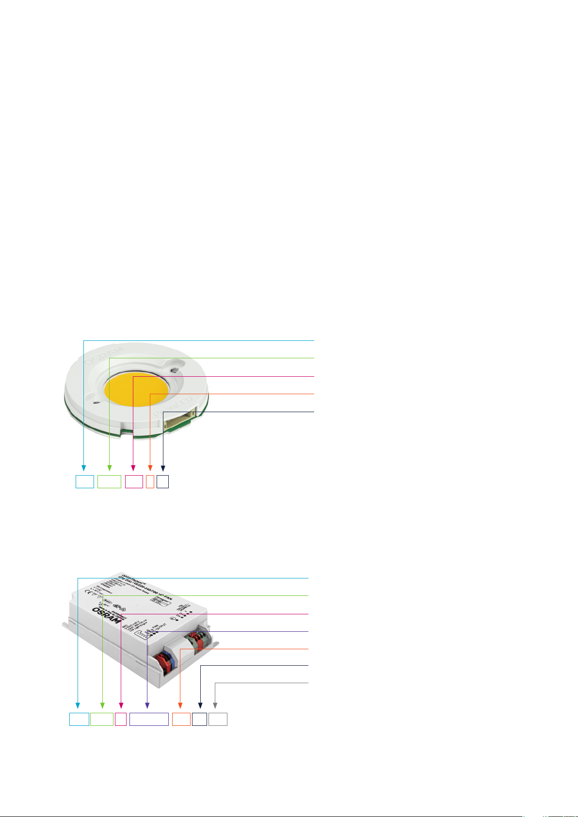
1.2.1. Nomenclature and marking
The PrevaLED
®
family follows a consistent naming
convention for identifying key parameters of the LED
module and the power supply. The nomenclature of the
LED modules and OPTOTRONIC
®
ECGs is as follows:
LED module:
LEP = LED module PrevaLED
®
5000 = 5000 lm
930 = CRI + CCT = CRI > 90 + 3000 K
C = Core, round shape
Z2 = Product generation Z2
LEP - 5000 - 930 - C - Z2
Power supply:
OTp DALI 45 / 220-240 / 700 HD FAN
OTp: OPTOTRONIC
®
PrevaLED
®
Control protocol: DALI (if applicable)
Wattage: 45 W
Input voltage: 220–240 V
Maximum output current: 700 mA
HD = High Dynamic
FAN = Ventilator/auxiliary output 5 V
6
Page 7
INTRODUCTION
1.2.2. Technical data
Technical data product family PrevaLED® Core Z2:
For current data, please see the PrevaLED
®
datasheet
at www.osram.com/prevaled-core.
PrevaLED® Core Z2
Technical data electronic control gear (ECG):
For current ECG data, please see the OPTOTRONIC
(OTp) datasheet at www.osram.com/prevaled-core.
1.2.3. Accessories
Cable kit
The cable is required for contacting and connecting the
individual PrevaLED
®
Core Z2 LED module with the power
supply. It ensures a fl exible and safe connection. This
cable kit is approved according to UL (Underwriters
Laboratories).
PrevaLED® Core Z2-
cable kit 800 lm,
1500 lm, 2000 lm, 3000 lm
PrevaLED® Core Z2-
cable kit 4000 lm
and 5000 lm
Cable clamp for OTp
This cable clamp can be clamped onto the ECG, turning
it into an ECG suitable for independent installation. It is
®
available for order for all OPTOTRONIC
OTp 45 versions.
®
OTp 35 and
ECG (OPTOTRONIC®)
Combinations of LED modules and ECGs:
For current combination possibilities, please see the
PrevaLED
®
datasheet at www.osram.COM/prevaled-core.
Within rated power, LED modules and power supplies can
be fl exibly combined, e.g. according to the favored control
option or form factor. A general requirement is that each
LED module is connected to an individual ECG.
The connection between the LED module and the ECG
should be established by means of the supplied cable kit.
Available in lengths 40 cm and 80 cm, please also refer to:
3.2. Wiring information.
Well-established form factors have been utilized for the
housings of the ECGs in order to ensure that existing
luminaire housings or accessories can be adopted to
PrevaLED
®
technology.
1.3. Zhaga – interchangeability of light engines
The Zhaga Consortium for the standardization of LED light
sources (LED light engines) is a worldwide cooperation
of luminaire and lamp manufacturers, producers of LED
modules and companies that supply the lighting industry.
The interchangeability of LED light engines is achieved
by defi ning fundamental interface parameters while still
leaving room for innovation in LED and driver technologies. Zhaga interface specifi cations cover the physical
dimensions, as well as the photometric, electrical and
thermal properties of different LED light engines.
The Zhaga Consortium was established in February 2010
and includes more than 180 companies (status: April
2012). OSRAM AG is a full member. The members
meet regularly in different regions of the world in order
to jointly work out the specifi cations. Large parts of the
new PrevaLED
®
Core portfolio fulfi ll the Zhaga specifi c ation book 3 for “spotlight systems with separate electronic
control gear.”
®
An updated list of all currently certifi ed PrevaLED
light
engines is available at: www.osram.com/zhaga.
For more information, please go to: www.zhagastandard.org.
7
Page 8
OPTICAL CONSIDERATIONS
2. Optical considerations
Chip-on-board-design (CoB)
So-called chip-on-board (CoB) light sources without
housing and with high-performance chips set very closely
next to each other have proven to be especially advantageous. Due to the large amount of applied chips, the size
of the light source is fl exible and scalable. In the application, the compactness, on the one hand, allows for very
high axis light and illumination levels, and, on the other
hand, a very high-contrast illumination with high brilliance.
Very good homogeneity (with a uniformity factor of 0.93) –
combined with constantly Lambertian radiation – additionally simplifi es refl ector design and facilitates the interchangeability of light sources.
PrevaLED
®
Core Z2
The CoB design is characterized by a large amount of
closely set LED chips, arranged in a certain grid which is
covered with luminescent material (cf. the image above).
One of the key advantages of this design is its very homogeneous light-emitting surface.
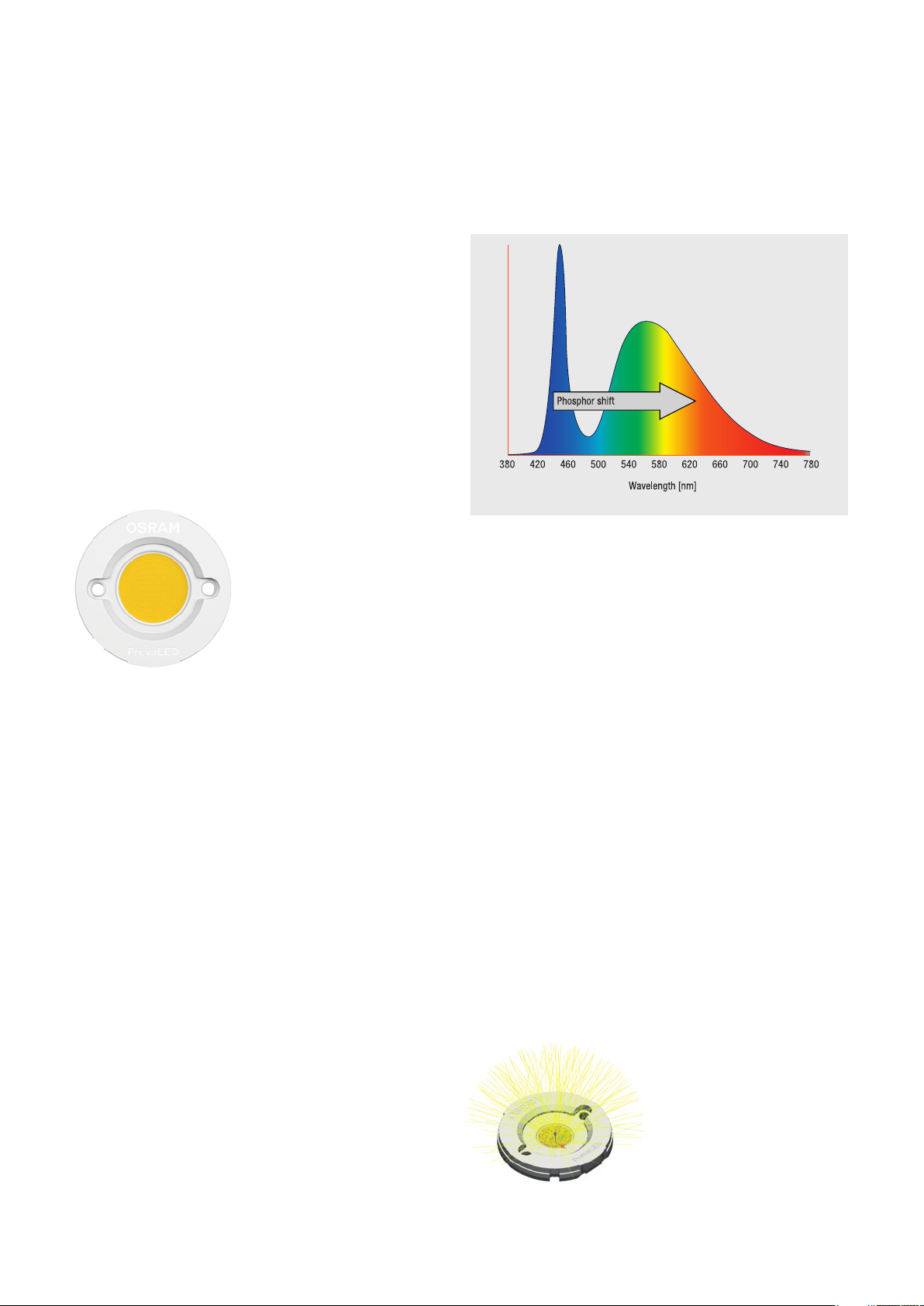
Pure phosphor conversion with CoB
Thanks to the use of pure phosphor conversion, the
PrevaLED
®
Core Z2 module can achieve a color rendering
quality of higher than CRI 90, while at the same time
providing a very homogeneous light output.
Phosphor conversion: By means of phosphor conversion, the blue
light of the LED chip is shifted towards the higher wavelengths of
green and red light.
2.1. Refl ector
High luminous densities (1.5–4.5 Mcd/m
2
) are the key
factor for LED-based lamps and luminaires in the area of
refl ector applications such as spotlights, for example.
For these, light sources with small light-emitting areas
and a high luminous fl ux are required (as realized with the
PrevaLED
®
Core Z2), because that way, the light can be
collimated especially well with refl ectors.
®
Thanks to CoB technology, the PrevaLED
Core Z2 has
a uniform light-emitting surface which, due to its great
homogeneity, eliminates the need to use diffuser material.
The minimized light-emitting surface (LES) and a refl ector
positioning close to the LES allows for better optical
handling. All in all, the properties of the PrevaLED
®
Core Z2
allow for the prevention of roughness and facets, which in
turn allows for minimal overall beam angles of 10° or less.
®
The high homogeneity of the PrevaLED
Core Z2 means:
• Low complexity in the surface structure of the refl ector
• Narrower beam angles <10° FWHM in combination with
minimized light-emitting surface
PrevaLED® Core Z2
8
Page 9

OPTICAL CONSIDERATIONS
2.1.1. Refl ector design
OSRAM provides mechanical (3D fi les) and optical
simulation data (ray fi les) to support customized refl ector
designs. These data are available upon request through
your sales partner or for public download at:
www.osram.com/prevaled-core.
Information on the optical calculation and simulation
for refl ector designs:
a) First estimation: Assumption of the LES ∅ as an
idealized, homogeneous, Lambertian emitter
b) Simulation via raytracing software:
• Ray fi les available upon request via OSRAM sales
department
• Photopia fi les are lodged under www.lti.com
The light distribution curve (LDC) of the module (without
further refl ectors, opt. systems) is characterized by a
universally applicable Lambertian distribution. Therefore,
it is very easy to defi ne and connect further downstream
optical systems (refl ectors, lenses, …).
More partners for support in the optics area can
be found in OSRAM’s LED Light For You network:
www.ledlightforyou.com. Moreover, standard components
and support for refl ector design and refl ector brackets are
available e.g. through the following partners:
ACL-Lichttechnik GmbH
A.A.G. STUCCHI
s.r.l.u.s. (Tool-less
+49 2173 9753 0
info@refl ektor.com
www.refl ektor.com
re fl ector brackets)
+39 0341 653111
info@aagstucchi.it
www.aagstucchi.it
Alux·Luxar
ALMECO S.p.A.
GmbH & Co. KG
+39 02 988963-1
+49 2173 279 0
sales@alux-luxar.de
info.it@almecogroup.com
www.almecogroup.com
www.alux.de
Jordan Refl ektoren
GmbH & Co. KG
Suitable and available
refl ectors can, for example,
be found on the web pages
+49 202 60720
of these partners.
info@jordan-refl ektoren.de
www.jordan-refl ektoren.de
C90
C0
LDC PrevaLED® Core Z2 –
without refl ector
LDC PrevaLED® Core Z2 –
with spot refl ector
PrevaLED® Core Z2
Please note that strong forces applied to the
housing can damage the LED module or the
housing, especially if the LED module isn’t
attached to a heat sink. Attach or remove the refl ector
only if the LED module is safely connected to a heat sink.
9
Page 10

OPTICAL CONSIDERATIONS
2.1.2. Refl ector mounting
The LED modules have a clearly defi ned optical contact
area (OCA) which provides a defi ned surface for attaching
the refl ector. In this confi guration, the mounting and
mechanical support of the refl ector must be ensured by
the luminaire body or by suitable structures for refl ector
mounting.
The following has to be considered when mounting the
refl ector: Due to the “air and creepage distances” specifi ed in the norm (IEC 61347-1/U935, among others), it is
recommended to stay within the OCA values of the corresponding category (see PrevaLED
the PrevaLED
®
Core Z2 and design support are available
®
datasheet). 3D fi les of
on the homepage www.osram.com/prevaled-core.
Design example: Conference room
The task here is to illuminate a conference room (approx.
5 x 4 m, height 2.8 m) in such a way that a medium illuminance (E
) of 500 lux is achieved on the work plane.
medium
By means of the EULUMDAT fi les provided by the refl ector
manufacturers, lighting design software and an assumed
maintenance factor of 0.69, the following example result is
achieved (calculated in DIALux with a Jordan fl ood refl ector,
article no. 113309010101): Illuminance diagram with 9
PrevaLED
®
Core Z2-based luminaires (LEP-2000-xxx-C-Z2):
2.1.3. Lighting design information
Computerized lighting design can be carried out with
free lighting design software such as DIALux and Relux
(www.dial.de or www.relux.biz).
Lighting designers can download or request the necessary
numerical luminous intensity distribution curves
(= EULUMDAT fi les in the .ldt format) for PrevaLED
®
Core
Z2 with the corresponding refl ector via the web page of
the respective refl ector manufacturer.
Ceiling height: 2800 mm,
Mounting height: 2851 mm
Figures in lux
Exemplary lighting design with 9 x PrevaLED® Core Z2 2000 lm in a
conference room
10
Page 11

OPTICAL CONSIDERATIONS
2.2. Luminous fl ux and color stability
Depending on the type of the LED module, the nominal
CCT is 2700 K, 3000 K, 3500 or 4000 K, respectively.
Depending on the variant, PrevaLED® Core Z2 modules
provide a module-to-module color variation of less than 3
threshold value units (MacAdams steps) on the Planckian
locus around this color target. These threshold value units
can be shown within the ANSI (American National Standards Institute) norm in the following way:
Measuring tolerance for color coordinates: ±0.01
2.3. Zhaga – optical interface
In order to achieve the interchangeability of refl ectors for
spot applications, Zhaga defi nes categories for the diameters of the light-emitting surfaces. PrevaLED
®
Core Z2
modules are available in the categories LES 9, LES 19 and
LES 23. With LED modules of the same category, optical
systems basically achieve the same beam angles and luminous intensities. With their homogeneity parameter U of
more than 90 % (i.e. with their very homogeneous radiation
without any additional light diffusion), the PrevaLED
®
Core
Z2 modules facilitate all further optical light shaping by
means of refl ectors or lenses. Around the light-emitting
surface, a ringshaped surface (optical contact area, OCA)
with a defi ned height is specifi ed where refl ector optics
can be attached. In addition to the surface described in
the Zhaga specifi cation, the OCA of PrevaLED
®
Core Z2
modules is positioned closer to the light-emitting surface,
so that refl ectors with smaller openings can also be used.
All PrevaLED
®
Core Z2 light engines fulfi ll the Zhagaspecifi ed requirements in terms of luminous fl ux, chromaticity coordinates and beam characteristics and partially
even exceed these requirements.
The luminous fl ux of each LED module depends on its
temperature. Therefore, 100 % of the luminous fl ux are
also achieved with the PrevaLED
®
Core Z2, i.e. until the
reference temperature (tr) is reached. When the reference
temperature is exceeded and up to maximum temperature
), the luminous fl ux is reduced to 95 %. If the maximum
(T
c
temperature is exceeded, a further luminous fl ux reduction
comes into effect until the PrevaLED
®
Core Z2 module is
fi nally switched off.
LES: Light-emitting surface
OCA (Optical contact area):
Attachment and reference
surface for optics
(e.g. refl ectors, lenses)
All fi gures in mm
11
Page 12

ELECTRICAL CONSIDERATIONS
3. Electrical considerations
3.1. Safety requirements
All OPTOTRONIC
PrevaLED
®
de vices with an output voltage of < 120 V
®
OTp devices intended for operating
Core LED modules are SELV*-equivalent
.
DC
The design of the LED modules ensures that the requirements of IEC 62031 for LED modules are met. The chips
on the LED module do not need to be covered in order to
fulfi ll the requirements of IEC 62031.
Due to its construction, the LED module can be mounted
directly on an exposed housing without further insulation.
The luminaire manufacturer is responsible for providing the
suitable and mandatory clearance and creepage distances
for the luminaire (for a light engine operating voltage of
< 120 V
*SELV = Safety extra-low voltage
).
DC
3.2. Wiring information
The recommended wire cross section on the primary side
of the OPTOTRONIC
nection between the OPTOTRONIC
®
OTp ECG is 0.5–1.5 mm2. The con-
®
ECG and the LED
module should be established by using the cable kit
available for order in lengths of 400 mm and 800 mm.
Components of the connection cable between
LED module and OTp
PrevaLED
®
cable sockets:
IN-CONNECTOR-CRIMPING SOCKET-TOP-LS2-5 RL 710
Part#: DF3-5S-2C, supplier: Hirose Electric Europe B.V.
(www.hirose.com)
• OTp-side (socket height: 4.6 mm/code#:
CL543-0006-6)
• Module-side (socket height: 4.25 mm/code#:
CL543-0193-5-00)
The Hirose crimping tool is recommended for custom izations of the connection cable.
Part#: DF3-TA22HC/550-0257-4-00
The cable material is UL-listed (UL E52653, UL E48762,
UL 10368) and fulfi lls fl ammability requirements according
to UL 94 V-0 and UL VW-1. The cables are approved for
up to 85 °C.
The maximum diameter of the cable is 5 mm, additional
details on the dimensions of the cable kit are specifi ed in
the illustrations on the next page.
For support with customizing cable lengths or construction, you can use the manual crimping tool from Hirose
Electric or contact your sales partner.
®
The cable for PrevaLED
Core Z2 has a fl at connector on
the module side and a higher connector (800 lm, 1500 lm,
3000 lm) on the OTp side, or open cable heads (4000 lm
and 5000 lm).
5-pin cable socket in
crimped condition
Pin 1 LED+
Pin 2 LED-
Pin 3 Aux. voltage
Pin 4 Sense comm.
Pin 5 Aux. gnd.
PIN assignment of connector
12
Page 13

ELECTRICAL CONSIDERATIONS
3.3. Wiring in class I and class II luminaires
Depending on the design of the luminaire according to
class I or class II requirements, a protective earth connection can be established for the OPTOTRONIC
®
ECG.
The functional earth (equipotential connection) may be
connected to the ECG to improve EMI behavior.
For these requirements, see the illustrations below.
Since the power supplies are SELV-equivalent, no
ad ditional electrical insulation has to be provided for
the LED module.
3.4. Optional cable clamp
For OPTOTRONIC
®
OTp 35 and OTp 45 types, an optional
cable clamp is available for order. This cable clamp can
be snapped onto the ECG and thus turns it into an ECG
suitable for independent installation with strain relief.
When using this cable clamp, luminaire design according
to IEC 60598-1 class I and class II is possible. In this regard,
functional earth may have to be observed as detailed above.
Please also note the installation requirements as supplied
with the cable clamp.
For more information on the cable clamp, see chapter
1.2.3. Accessories (p. 7).
Earth connection is mandatory in class I luminaires and
improves EMI compliance according to EN 55015.
In class II luminaires do not connect earthing terminal.
13
Page 14

ELECTRICAL CONSIDERATIONS
3.5. Electrostatic safety measures
In order to safely handle components susceptible to electrostatic discharge (ESD), an adjusted production environment is necessary. This is specifi ed in IEC 61340-5-1
(“Electrostatics – Part 5-1: Protection of electronic devices
from electrostatic phenomena – General requirements”).
Based on the human body model (HBM), the following
maximum voltages apply for the PrevaLED
®
Core Z2:
3.6. Inrush current limitation
Electronic drivers are subject of a certain inrush current.
For the OPTOTRONIC
®
control gears for the PrevaLED®
Core Z2, this current is very low. That is why up to 15 OTp
(35/45) can be applied at one 16-A circuit breaker.
3.7. Connection information
The energized light engine system must not be
serviced. This includes disconnecting or connect-
ing the electrical contact of the LED module
and the ECG. In exceptional cases, such as fi nal assembly, the connection cable can be disconnected from the
LED module or the OTp and then reconnected (20 times
max. with one-minute intermissions).
3.8. Zhaga – electrical interface
Zhaga defi nes no requirements for the electrical interface
between the ECG and the module. For Zhaga categories
and the dimensions of the control gears, please see the
technical datasheet.
Material HBM Class
LEP-800-xxx-C-Z2 4 kV 2
LEP-1500-xxx-C-Z2 8 kV 3B
LEP-2000-xxx-C-Z2 8 kV 3B
LEP-3000-xxx-C-Z2 8 kV 3B
LEP-4000-xxx-C-Z2 8 kV 3B
LEP-5000-xxx-C-Z2 8 kV 3B
14
Page 15

THERMAL CONSIDERATIONS
4. Thermal considerations
The proper thermal design of an LED luminaire is critical
for achieving the best performance and ensuring the long
lifetime of all components. Because the PrevaLED
®
Core
Z2 ensures high effi ciencies, only a partial amount of the
introduced electrical power still has to be dissipated
through the back of the light engine (see also: 1.2.2. Tech-
nical data (p. 7)).
Depending on the application and the chosen LED
module, passive cooling can be suffi cient. In critical applications (e.g. small available heat sink size in combination
with high-power LED modules), active cooling by means
of a ventilator may be needed. Active cooling combines a
heat sink with a fan or a similar device to maximize the
cooling power out of an existing, passive heat sink.
4.1. Thermal interface material and other accessories
When mounting a PrevaLED
®
Core Z2 within a luminaire,
it is highly recommended to use thermal interface material
(TIM) between the back of the LED module and the luminaire housing. Either heat-conductive paste or foil can be
used. In order to balance possible unevenness, the material should be applied as thinly as possible, but as thickly as
necessary. In this way, air inclusions, which may otherwise
occur, are replaced by TIM and the required heat conduction between the back of the LED module and the contact
surfaces of the luminaire housing are achieved. For this
purpose, the planarity and roughness of the surface
should be optimized.
For initial application designs, applicably pre-pierced thermal interface material (e.g. Kerafol’s Keratherm 86-82) with
a diameter of 50 mm and matching mounting holes can
be ordered through the Alfatec company (see the partner
information below). The list below shows a selection of
suppliers of passive and active cooling solutions as well
as thermal interface materials.
Additional partners for thermal management support can
also be found in OSRAM’s LED Light For You network:
www.ledlightforyou.com.
Active cooling systems:
AVC www.avc-europa.de
Cooler Master www.coolermaster.com
Nuventix www.nuventix.com
Sunon www.sunoneurope.com
Heat sinks:
Aavid Thermalloy www.aavidthermalloy.com
Cool Innovations www.coolinnovations.com
Fischer Elektronik www.fi scherelektronik.de
Meccal www.meccal.com
Pinbloc www.pinbloc.de
Radian www.radianheatsinks.com
R-Theta www.r-theta.com
Wakefi eld www.wakefi eld.com
Thermal interface materials:
Aavid Thermalloy www.aavidthermalloy.com
Alfatec www.alfatec.de
Arctic Silver www.arcticsilver.com
Bergquist www.bergquistcompany.com
Chomerics www.chomerics.com
Dow Corning www.dowcorning.com
Electrolube www.electrolube.com
Kerafol www.kerafol.de
Kester www.kester.com
Kunze Folien www.heatmanagement.com
Laird www.lairdtech.com
MG Chemicals www.mgchemicals.com
Thermafl o www.thermafl o.com
Thermagon www.thermagon.com
Wakefi eld www.wakefi eld.com
Heat pipes:
DAU www.dau-at.com
MB Electronic AG www.mb-electronic.de
Simulation software:
Comsol www.comsol.de
Flotherm www.mentor.com
SolidWorks www.solidworks.com
Thermal probes/thermocouples:
B+B Thermo-Technik www.bubthermo.de
OMEGA www.omega.de
15
Page 16

THERMAL CONSIDERATIONS
4.2. Heat sink
Basically, the heat sink has to fulfi ll two tasks:
a) Heat spreading through heat conduction
The task here is to spread the heat as uniformly as possible from the contact surface of the LED module through
the heat sink material and into the cooling fi ns. In this
respect, the thermal conductivity and the material cross
sections of the heat sink play a decisive role (cf. the thermal
conductivities table below).
b) Heat dissipation to the surrounding medium
(usually ambient air)
For this task, the heat sink design in terms of fi n and surface confi guration is decisive. By adequate geometrical
forming, heat conduction through convection and IR radiation can be signifi cantly infl uenced and improved (cf. the
table with the IR emission coeffi cients on the next page).
Thermal conductivities of selected materials
Material Specifi c heat
Copper 380–401
conductance value
[W/(m · K)]
Very good heat
conduction
Thermal conduction
resistance (R
) formula:
th
L
R
=
th
A ·
L: Length through the material in
fl ow direction [m]
A: Material cross section/surface
of the heat sink [m
A
2
]
L
Aluminium 200–220
Brass 120
Steel 42–58
Stainless steel 15
Glass 1
Wood 0.13–0.18
Air (dry at 1013 mbar,
no dissipation)
0.0256 at 20 °C
Bad/no
cooling
16
Page 17

THERMAL CONSIDERATIONS
For necessary heat transfer and good cooling, the surface
of the applied heat sink material, with regard to heat
emission, must be considered. In order to achieve very
good radiation behavior to the ambient space, it can be
advantageous to use heat sinks with a matt black fi nish.
Within typical applications such as downlights in recessed
ceilings, it can be an advantage to use black anodized
heat sinks.
For the optimization of the radiation, special lacquers
with a high emission ratio, as typically used for radiators
instead of anodization, are available.
Overview of selected materials with
different surfaces
Material Emission
ratio
Temperature *
[°C]
Low cooling
effect
Aluminium plate,
blank, rolled
Aluminium, die-cast
surface, blank
Aluminium, black
anodized
Steel, powder-coated 0.85 25
Aluminium, matt
black fi nish
*) Temperature of the material at which
the emission ratio was measured
0.022 25
0.040 170
0.4 170
0.600 40
0.970 80
High cooling
effect
4.3. Temperature measurement
Measuring the temperature helps controlling the LED module’s operating parameters. After fi xing the LED module
into the luminaire, the temperature has to be measured at
the thermal interface point (T
point), within the planned
c
ambient and operation conditions.
Thermal interface point (T
is measured in the center of the back of the LED module
T
c
The thermal interface temperature (case temperature/T
point)
c
c
) is
measured in the center of the back of the LED module, by
means of a thin milled channel (in the LED module or the
luminaire) or hole (∅ approx. 2 mm) which is drilled into
the luminaire prototype for the thermocouple.
With this temperature measurement, as applied at the measuring point of the LED module, the actual T
temperature
c
can be determined. By means of suitable cooling methods
(active or passive cooling), this temperature must be maintained under the maximum temperature specifi ed in the
datasheet.
Based on the measured interface temperature (T
ambient temperature (t
mance (P
), you can determine the necessary thermal
th,mod
resistance of the cooling system (R
) and the thermal module perfor-
a
KS).
th
) of the
c
In order to do so, a thermocouple has to be affi xed to
point, preferably by gluing (e.g. by means of a heat-
the T
c
conducting adhesive such as “Arctic Silver”).
a
th, mod
temperature
c
Formula for calculating the T
Tc-t
R
KS =
th
P
Rth KS = Thermal resistance cooling system
T
= Temperature Tc point
c
= Ambient temperature (usually air temperature of the room)
t
a
= Thermal module performance
P
th, mod
17
Page 18

THERMAL CONSIDERATIONS
Recommended thermocouples
Description Temperature [°C] Length [mm]
All figures in mm
4.4. Thermal simulation
Using a computer, matching heat sink housing forms and
occurring maximum temperatures can be calculated by
means of numerical heat simulation.
Two thermo simulation examples:
T heat sink:
46…49 °C
T ambient: 25 °C
Surface area ~ 0.25 m2
(P115 80 Meccal)
Thermal probe -10…+100
Adhesive foil probe -50…+250
Thermal model description:
PrevaLED
®
Core Z2
2000
cable
1000
wire
TC: 47 °C
T heat sink:
38…41 °C
T ambient: 25 °C
Surface area ~ 0.5 m2
(P 200 84 Meccal)
TC: 39 °C
PrevaLED
150 mm in downlight orientation
®
LEP-2100 on heat sink with extruded profi le –
3D fi les for thermal simulation can be found at:
www.osram.com/prevaled-core.
18
Page 19

THERMAL CONSIDERATIONS
4.5. ECG thermal considerations
The installation of the ECG must ensure that the maximum
temperature at the T
thermal considerations for OPTOTRONIC
found in the technical guide for OPTOTRONIC
is not exceeded. Further details on
c
®
devices can be
®
, available
at: www.osram.com/optotronic.
4.6. Thermal management and lifetime
The PrevaLED
®
Core Z2 has a lifetime of 50,000 h
(L70B50*). If the temperature is exceeded, the specifi cation is left and, after further heat-up, the LED module is
switched off. Liftetime information (see datasheet) as well
as guarantee information for LED modules combined with
ECG at: www.osram.com/prevaled-core.
**
*) L70B50 defi nition: After 50,000 h, at least 50 %
of the observed LED modules still show 70 % of
the initial luminous fl ux.
**) The guarantee conditions can be found at
www.osram.com/system-guarantee.
4.7. Zhaga – thermal interface
Verifi cation of thermal interchangeability according to Zhaga:
Determine the thermal resistance
of the luminaire
Choose an applicable module
Examples for luminaire Rth curves
19
Page 20

THERMAL CONSIDERATIONS
The thermal test engine (TTE) for the determination
of thermal resistance:
With the TTE according to Zhaga specifi cation, the introduction of the heat output into an existing luminaire can
be simulated. To do so, the following work steps need to
be taken:
1. Installation of the TTE with thermal interface material
(TIM) into the luminaire prototype to be measured
2. Introduction of different heat outputs P
TTE
(e.g. in 10-W steps)
3. Measurement of the reference temperature t
r, TTE
after temperature stabilization, by means of the
thermo couple attached in the TTE
4. Thermal resistance calculation
t
=
r, TTE-ta
P
TTE
dependent on P
th, lum
, as shown in
TTE
R
th, lum
5. Draw the graph of R
the diagram
Choosing the suitable module:
The datasheet shows heat output values of the module
) for all versions of the PrevaLED® Core Z2 as well as
(P
th, mod
the maximum permissible thermal resistances (R
th, mod, max
).
Two examples are shown in the diagram. The datasheet
values are specifi ed for t
ambient temperature ta’, the corresponding R
= 25 °C, in case of a differing
a
th, mod, max
can
be calculated according to the following formula:
Additionally, a simple thermal ECG dummy can be used
for the simulation of the thermal power loss in the application (simulation of additional heat input, e.g. in case of
suspended ceilings).
Thermal OTp tester
'- 25 °C
t
R
th, mod, max (ta')
= R
th, mod, max (25 °C)
a
P
th, mod
All modules of which the data points are located on or
above the curve are suitable for application in the luminaire.
In the example shown in the illustration above, LEP-1500835-Z2 is suitable for application in both luminaires,
whereas LEP-2000-835-Z2 is suitable for luminaire 2 only.
Although suitable modules can be easily and clearly
determined with this method, we nevertheless recommend
verifying the thermal design by means of measurements
with real modules, as outlined in chapter 4.3.
The TTE serves the thermal measurement of an existing
cooling method or housing.
By means of their maximum cooling performance [W] as
based on T
max. [°C], it is therefore easily possible even
c
in the future to equip once thermally measured luminaires
with standardized light engines.
TTE engineering drawing at: www.osram.com/prevaled-core
20
Page 21

MECHANICAL CONSIDERATIONS
5. Mechanical considerations
5.1. LED module dimensions
This schematic drawing contains further details on the
dimensions of available PrevaLED
For 3D fi les, LES and OCA categories, see the datasheet
at: www.osram.com/prevaled-core. These 3D fi les in differ-
ent formats may be used for the construction of luminaires.
®
Core Z2 LED modules.
5.2. Mechanical protection of the LED module
The pressure-sensitive LES (light-emitting surface) of the
LED module is protected against mechanical infl uence by
a protective foil. The LED module must not be switched
on if the protective foil is still in place because it could
be destroyed. Please do not apply pressure on the LES,
neither before nor after installation and removal of the
protective foil.
For operation in damp, wet or dusty environments, the
user has to make sure that an adequate ingress protection
and the protection of the LED module and the ECG is
warranted by means of a suitable IP classifi cation of the
luminaire housing (in due consideration of the luminaire
standard IEC 60598-1, irrespective of the different requirements in indoor and outdoor areas).
LES: Light-emitting surface
OCA (Optical contact area): Attachment and reference
surface for optics (e.g. refl ectors, lenses)
All fi gures in mm
kg
21
Page 22

MECHANICAL CONSIDERATIONS
5.3. ECG dimensions
Detailed mechanical drawings and 3D fi les are available
at our website.
OTp 15
(acc. to Zhaga: Driver category CS1)
All fi gures in mm
Depending on the thermal interface material and contact
surface conditions, the recommended screwing torque
can be between 0.4 and 0.6 Nm. A higher torque level
does not necessarily lead to signifi cantly better heat
transfer, but may lead to damage of the LED module.
The recommended counter sink diameter of the mounting
holes for good thermal performance should be 3.5 mm
max. A bigger counter sink can lead to mechanical deformation of the PCB and thus to a deterioration of the
thermal connection to the heat sink. When mounting the
module with self-cutting screws, an additional torque
may be required to prepare the thread.
Due to a large number of possible combinations when
choosing thermal interface material, heat sinks and screws,
any chosen combination should be carefully checked and
tested in order to maximize the heat transfer between the
LED module and the heat sink. Optimal mounting can lead
to a lower operating temperature of the LED module and
thus to an improved performance of the system.
All OTp 35 and OTp 45 types
(acc. to Zhaga: Driver category AM3)
OTp 60
• The housing material of these devices (OTp 15/35/45)
is PBT and complies with UL 94 V-0.
• For input wiring on the network side, the housing
provides push-in terminals.
• It is recommended to use screws with washers when
attaching the ECGs to the luminaire.
5.4. LED module attachment
PrevaLED
®
Core Z2 modules are attached to a heat sink
with two M3 screws through the mounting holes within
the LED module. The mounting holes are reinforced with
metal. Only in this way can a suffi cient thermal contact be
ensured throughout the lifetime of the module, because
synthetics will, due to the infl uence of pressure and temperature, give way after some time.
PrevaLED ® Core Z2
All fi gures in mm
(except where noted otherwise)
5.5. Zhaga – mechanical interface
In order to ensure the interchangeability of spot LED light
engines, Zhaga has defi ned maximum dimensions as well
as the screw positions for mounting the module. The
planarity of the luminaire side of the mounting surface, for
example, is not defi ned. For a fairly good heat transfer to
the heat sink, we recommend a planarity of < 0.1 mm and
a roughness of < 3.2 μm, as usually achieved by surfaces
with a milling fi nish.
22
Page 23

ASSEMBLY IN A REFERENCE LUMINAIRE
6. Assembly in a reference luminaire
To demonstrate the light engine concept and the design
of a luminaire, the following pages will lead you through
an exemplary assembly of a reference luminaire, using
the 2000-lm PrevaLED
The fi rst picture shows the different components
of the complete system:
• Housing (acts as a heat sink)
• Refl ector
• Cover
• Decorative ring
• Mounting ring
• Main connection wire
• Cable kit
• Thermal interface material
• Light engine
As a fi rst step, the thermal interface material has to be
applied within the light fi xture housing and/or the heat
sink.
®
light engine.
1
3
2
4
6.1. Preparation
After applying the thermal interface material, the LED
module has to be attached to the surface. For mounting
instructions and screw selection, please see the instruction in chapter 5.4. LED module attachment.
To ease the centering of the LED module, small plastic
sticks or pins can be inserted into the screw holes in the
heat sink to guide the LED module into the right place.
After centering, these guiding pins can be removed and
replaced by the screws.
5
7
6
8
23
Page 24

ASSEMBLY IN A REFERENCE LUMINAIRE
6.2. Wiring and refl ector/cover
The corresponding cable kit can be used to connect the
LED module to the power supply. To get the connector
easily into the housing, we recommend a through hole
with a minimum diameter of 10 mm.
Once the LED module is connected, the refl ector can
be attached to the housing and the diffuse cover can be
placed on top of the luminaire.
Both components have to be properly centered above the
LED module.
9
10
®
6.3. Commissioning the PrevaLED
light engine
After the fi xation of the mounting ring, the optional
decorative ring can be attached.
As an example for an electrical connection within a class II
installation, the two wires for the main connection have to
be connected to the OPTOTRONIC
®
power supply.
In a class I installation, the protective earth has to be
connected additionally.
Finally, the complete system can be connected to the
mains and powered up.
11
13
15
12
14
16
17
19
18
24
Page 25

NORMS AND STANDARDS
7. Norms and standards
7.1. Norms and standards for PrevaLED® LED modules and light engines
®
PrevaLED
Zhaga-specifi cation book 3: Spotlight systems with separate
electronic control gear
Core Z2 complies with the following standards:
According to the EC declarations (European directive: 2006/95/EC, European
directive: 2004/108/EC), PrevaLED
Safety of LED modules: IEC 62031
Photobiological safety: IEC/TR 62471-2 (typenabhängig)
Electromagnetic compatibility: DIN EN 55015
DIN EN 61547
DIN EN 61000-3-2
DIN EN 61000-3-3
Ingress protection: IP 20
Vibration, shocks, tensile strength: IEC 60068-2-6
IEC 60068-2-27
IEC 60068-2-21
7.2. Norms and standards for control gears
Safety: IEC 61347-1, IEC 61347-2-13
Performance: IEC 62384
Radio interference: EN 55015 (A1:2007, A2:2009)
Harmonic content: IEC 61000-3-3:2008
Immunity: IEC 61547:2009
®
Core Z2 complies with the following norms:
Temperature range: See corresponding value within the datasheet
Galvanic insulation between
primary and secondary side: 3 kV
No-load proof: Yes
Short circuit proof: Yes
Overload protection: Automatic shutoff, reversible
Overheating protection: Automatic shutoff, reversible
Connection, primary: For OTp 15 HD: screw-terminals
For OTp 35 HD and OTp 45 HD: push-in terminals
Cross section, primary: 0.5 mm
Connection, secondary: 5-pin connector, for use with cable kit
Cross section, secondary: Only for use with special cable kit
Dimensions (L x W x H): 123 x 79 x 33 mm for all OTp 35 and all OTp 45
109 x 50 x 35 mm for OTp 15 HD
Approvals:
For test and certifi cation measurements,
a mains voltage of 230 is recommended.
rms
2
–1.5 mm
2
0 i
]
25
Page 26

NORMS AND STANDARDS
7.3. Photobiological safety
Looking directly at high-performance light sources can
(just approximate classifi cation of safety classes like
looking directly at the sun) be a hazard to the retina of
the human eye. This is why the PrevaLED
have been tested regarding the risk group defi nition within
the framework of EN 62471:2008.
According to EN 62471-1, PrevaLED
have to be classifi ed in risk group 1. In absence of UV and
IR radiation, no labeling is required in RG 1 (TR 62471-2).
®
LED modules
®
Core LED modules
26
Page 27

de
www.osram.com/prevaled-core
www.osram.dewww.osram.
OSRAM GmbH
Head Office
Marcel-Breuer-Strasse 6
80807 Munich
Germany
Phone +49 (0)89-6213-0
Fax +49 (0)89-6213-20 20
www.osram.com
06/13 Subject to change without notice. Errors and omission excepted.
 Loading...