

Page 1

www.osram.com/prevaled-core
Application guide.
PrevaLED® Core light engines.
OCTOBER
2011
Page 2

CONTENTS
Please note:
All information in this guide has been prepared with great care.
OSRAM, however, does not accept liability for possible errors,
changes and/or omissions.
Please check www.osram.com/prevaled-core or contact your sales
partner for an updated copy of this guide.
2
Page 3

CONTENTS
1. Introduction 4
1.1. System overview 4
1.2. System information 7
1.2.1. Nomenclature and marking 7
1.2.2. Technical data 8
1.2.3. System combinations 10
1.2.4. Accessories 12
2. Optical considerations 14
2.1. Refl ector 16
2.1.1. Refl ector design 17
2.1.2. Refl ector mounting HD version 18
2.1.3. Refl ector mounting ECO Z2 version 18
2.2. Light color stability 19
3. Electrical considerations 20
3.1. Safety requirements 20
3.2. Wiring information 20
3.3. Wiring in class I and class II luminaires 22
3.4. Optional cable clamp 22
3.5. ESD protection of light engines 23
3.6. Ingress protection 23
5. Mechanical considerations 34
5.1. Light engine dimensions 34
5.2. ECG dimensions 36
5.3. Light engine mounting 37
6. Fixation in a luminaire (example) 38
6.1. Preparation 39
6.2. Wiring and refl ector/cover 40
®
6.3. Commissioning PrevaLED
41
7. Norms and standards 42
7.1. Standards for PrevaLED
®
42
7.2. Power supply standards and
features applicable to PrevaLED® 43
7.3. Interchangeability of LED light engines 44
7.4. Photobiological safety 44
4. Thermal considerations 24
4.1. Thermal interface material and
other accessories 24
4.2. Heat sink size 25
4.3. T
measurement 30
c
4.4. Thermal simulation 32
4.5. ECG thermal considerations 33
3
Page 4

INTRODUCTION
1. Introduction
1.1. System overview
Brightness levels of today’s LEDs are opening the door for
usage of LEDs in general lighting applications requiring high
lumen output levels. Building an LED-based luminaire poses
a new set of technical challenges, among them new optical
requirements, providing adequate thermal management for
stable operation and lastly dealing with the ever-improving
performance of LEDs.
OSRAM’s PrevaLED
®
family of LED light engines addresses
the challenges of LED-based lighting while at the same time
providing great performance and fl exibility to the user.
The PrevaLED
®
Core series of light engines is ideally suited
for use in refl ector-based, rotational symmetrical applications
such as downlights or spotlights. These light engines provide
several convincing benefi ts in the application:
• PrevaLED
®
Core light engines are available as a system
of matching light engines and ECGs and deliver maximum
performance at very high levels of effi ciency.
• The light engines provide superior optical performance,
both in optical effi ciency as well as high quality of light
(color rendering).
• The wide range of lumen packages (currently available
from 800–3000 lm) allows addressing a wide range of
applications based on a single platform of light engines,
all delivering the same quality of light and performance.
It is, for example, possible to create a range of spotlights,
ranging from halogen-class up to HID levels, all with the
same optical characteristics, delivering a consistent expe-
rience for the end user.
• Thanks to high thermal and optical performance, luminaires
based on PrevaLED
®
Core light engines can be realized
with minimized size of required heat sink and refl ector,
giving a greater design fl exibility to the user.
• PrevaLED
®
Core light engines provide stable interfaces for
the user, in particular by defi ning stable lumen packages
over time. Independent of future increases in LED effi cacy,
the lumen output of a given type of light engine will remain
constant, but at lower power consumption. In this way, a
luminaire designed on the PrevaLED
®
Core platform will
automatically benefi t from effi cacy improvements without
needing a lengthy and costly redesign of the base con-
struction.
4
Page 5

INTRODUCTION
Movable 3D PrevaLED Core ECO Z2 (works with Adobe Acrobat 7 or higher)
PrevaLED® Core light engines are available in different perfor-
mance grades, namely lumen output and color rendering. At
present, the available systems are:
• Lumen packages of 800–3000 lm are available with a high-
quality color rendering (HD light engines – see nomencla-
ture – with CRI > 90/85). Due to internal construction with
a high-dynamic optical control of color point, these light
engines provide exceptional stability of color temperature
and module-to-module consistency.
• For basic applications, the lumen packages of 800–
3000 lm are also available in CRI 80. These light engines
employ a modifi ed housing construction leading to a better
effi cacy of the light engine.
The PrevaLED® system consists of an LED light
engine, dedicated OTp and connecting cable.
Besides providing superior quality of light, the HD-type light
engines also outperform typical modules based on single-
phosphor white LEDs. The effi cacy of the light engines not
only results in minimized energy consumption of the lumi-
naire, but also reduces the thermal load on the luminaire,
allowing for smaller and lighter designs of the heat sink.
All HD types are available in 3000 K and 4000 K CCT. The
CRI 80 (Z2) types are available in fl ux packages of 800 lm,
1500 lm, 2000 lm and 3000 lm in color temperatures of
2700 K, 3000 K, 3500 K and 4000 K.
PrevaLED
OPTOTRONIC
®
Core light engines must be operated with
®
power supplies of the “OTp” type. Available
types and valid system confi gurations are detailed in the next
section.
Additional details on optical, thermal, mechanical and electri-
cal characteristics can be found in the following sections.
Additional and updated information (as well as updates of
this guide) will be posted at
www.osram.com/prevaled-core.
OSRAM also provides an extensive range of energy-saving
light management components, such as sensors and room
controllers. By use of these products, additional energy
savings can be realized. For an overview of these products,
please visit
www.osram.com/lms.
5
Page 6

INTRODUCTION
PrevaLED® Core HD: Four lumen stacks
3000 K
4000 K
PrevaLED
800 m 1500 lm 2100 lm 3000 lm
800 lm 1500 lm 2100 lm 3000 lm
LEP-800-930-HD-C LEP-1500-930-HD-C LEP-2100-930-HD-C LEP-3000-930-HD-C
LEP-800-840-HD-C LEP-1500-840-HD-C LEP-2100-840-HD-C LEP-3000-840-HD-C
®
Core ECO Z2: Four lumen stacks
800 lm 1500 lm 2000 lm 3000 lm
2700 K
3000 K
3500 K
4000 K
6
800 lm 1500 lm 2000 lm 3000 lm
LEP-800-827-C-Z2 LEP-1500-827-C-Z2 LEP-2000-827-C-Z2 LEP-3000-827-C-Z2
LEP-800-830-C-Z2 LEP-1500-830-C-Z2 LEP-2000-830-C-Z2 LEP-3000-830-C-Z2
LEP-800-835-C-Z2 LEP-1500-835-C-Z2 LEP-2000-835-C-Z2 LEP-3000-835-C-Z2
LEP-800-840-C-Z2 LEP-1500-840-C-Z2 LEP-2000-840-C-Z2 LEP-3000-840-C-Z2
Further lm stacks of 4000 lm and 5000 lm will be available in 2012.
Page 7

1.2. System information
1.2.1. Nomenclature and marking
The PrevaLED® family follows a consistent naming conven-
tion for identifying key parameters of the light engine and
the power supply. The nomenclature of light engines and
OPTOTRONIC
®
ECGs is as follows:
INTRODUCTION
Light engine:
LEP-3000-930-HD-C-Z2
Power supply:
LEP = Light engine PrevaLED
®
3000 = 3000 lm
930 = CRI + CCT = CRI > 90 + 3000 K
HD = High Dynamic*
C = Core, round shape
Z2 = Product generation Z2 (if applicable)
OTp: OPTOTRONIC® PrevaLED
®
Control protocol: DALI (if applicable)
Wattage: 45 W
OTp DALI 45/220-240/700 HD FAN
* If HD is not noted, the light engine is an ECO type.
Input voltage range: 220–240 V
Maximum output current: 700 mA
HD = High Dynamic*
FAN = connector/auxiliary output
7
Page 8

INTRODUCTION
1.2.2. Technical data
All values regarding system effi ciency and system power
consumption include the complete system and are based on
T
maximum:
c
Light engine
(at T
max)
c
Power supply
+
(at Tc max)
All values regarding light engine effi ciency and light engine
power are based on T
Technical data product family PrevaLED
Light engine System/
maximum.
c
light engine
®
Core
Luminous
fl ux
System/
light engine
[lm]
Power
[W]
Effi cacy
[lm/W]
PrevaLED® Core HD
LEP-3000-930-HD-C
LEP-3000-840-HD-C
LEP-2100-930-HD-C
LEP-2100-840-HD-C
43/39 3,000 70/77 3,000 > 90 >130 < 3 50,000 60
43/39 3,000 70/77 4,000 > 85 >130 < 3 50,000 65
28/25 2,100 75/84 3,000 > 90 >130 < 3 50,000 65
28/25 2,100 75/84 4,000 > 85 >130 < 3 50,000 65
CCT
[K]
CRI Viewing
angle
[°]
Initial
SDCM
PrevaLED® Core HD
Lifetime
L70/B50
at T
max.
c
[h]
max
T
c
[°C]
LEP-1500-930-HD-C
LEP-1500-840-HD-C
16/19 1,500 75/84 3,000 > 90 >130 < 3 50,000 65
16/19 1,500 75/84 4,000 > 85 >130 < 3 50,000 65
LEP-800-930-HD-C 11/9 800 75/88 3,000 > 90 >130 < 3 50,000 65
LEP-800-840-HD-C 11/9 800 75/88 4,000 > 85 >130 < 3 50,000 65
8
Page 9

INTRODUCTION
PrevaLED® Core ECO Z2
Light engine System/
light engine
Power
[W]
PrevaLED
®
Core ECO Z2
Luminous
fl ux
[lm]
System/
light engine
Effi cacy
[lm/W]
CCT
[K]
CRI Viewing
angle
[°]
Initial
SDCM
Lifetime
L70/B50
at T
max.
c
[h]
max
T
c
[°C]
LEP-3000-827-C-Z2 36/31 3,000 84/97 2,700 80 >120 < 4 50,000 65
LEP-3000-830-C-Z2 33/29 3,000 90/104 3,000 80 >120 < 4 50,000 65
LEP-3000-835-C-Z2 32/29 3,000 93/107 3,500 80 >120 < 4 50,000 65
LEP-3000-840-C-Z2 32/28 3,000 94/108 4,000 80 >120 < 4 50,000 65
LEP-2000-827-C-Z2 32/28 2,000 62/72 2,700 80 >120 < 4 50,000 65
LEP-2000-830-C-Z2 29/25 2,000 68/79 3,000 80 >120 < 4 50,000 65
LEP-2000-835-C-Z2 29/25 2,000 70/81 3,500 80 >120 < 4 50,000 65
LEP-2000-840-C-Z2 28/24 2,000 71/82 4,000 80 >120 < 4 50,000 65
LEP-1500-827-C-Z2 22/19 1,500 67/80 2,700 80 >120 < 4 50,000 65
LEP-1500-830-C-Z2 21/17 1,500 73/87 3,000 80 >120 < 4 50,000 65
LEP-1500-835-C-Z2 20/17 1,500 74/89 3,500 80 >120 < 4 50,000 65
LEP-1500-840-C-Z2 20/17 1,500 75/90 4,000 80 >120 < 4 50,000 65
LEP-800-827-C-Z2 12/10 800 65/79 2,700 80 >120 < 4 50,000 65
LEP-800-830-C-Z2 12/10 800 65/79 3,000 80 >120 < 4 50,000 65
LEP-800-835-C-Z2 12/10 800 65/79 3,500 80 >120 < 4 50,000 65
LEP-800-840-C-Z2 12/10 800 69/84 4,000 80 >120 < 4 50,000 65
9
Page 10

INTRODUCTION
Technical data ECG
ECG Nominal
power
[W]
Con-
trol
Auxiliary
output
[V/W]
Ta
[°C]
Tc
max
[°C]
Lifetime
L70/B50
at T
max.
c
ECG (OTPOTRONIC®)
Dimensions
[mm]
[h]
Length
Width
Height
OTp DALI 45/220-240/700 HD FAN (*) 45 DALI 5/1 -20…50 80 50,000 123 79 33
OTp 45/220-240/700 HD FAN (*) 45 – 5/1 -20…50 75 50,000 123 79 33
OTp 45/220-240/700 HD (*) 45 – – -20…50 80 50,000 123 79 33
OTp DALI 35/220-240/700 HD (*) 35 DALI – -20…50 80 50,000 123 79 33
OTp 35/220-240/700 HD (*) 35 – – -20…50 75 50,000 123 79 33
OTp 35/220-240/700 (*) 35 – – -20…50 80 50,000 123 79 33
OTp 15/220-240/700 HD (*) 15 – – -20…50 75 50,000 109 50 35
Cable clamp kit for strain relief available, see 1.2.4. Accessories (page 13).
(*) Target values
1.2.3. System combinations
Within rated power, light engines and power supplies can be
fl exibly combined, e. g. according to desired control option
The connection between light engine and ECG should be
established by supplied cable kit. Available in lengths 40 cm
and 80 cm, please also refer to: 3.2. Wiring information.
or form factor. Valid and possible combinations of light en-
gines and ECGs are listed below, a general requirement is
that HD light engines require the use of “HD” ECGs and that
each light engine is connected by a single ECG.
All ECGs utilize well-established housing form factors to facili-
tate adoption of existing luminaire housings or accessories to
the PrevaLED
®
technology.
10
Page 11

Compatibility chart PrevaLED
®
light engine – ECG
INTRODUCTION
LEP-3000xxx-HD-C
LEP-2100xxx-HD-C
LEP-1500xxx-HD-C
LEP-800xxx-HD-C
LEP-30008xx-C-Z2
LEP-20008xx-C-Z2
LEP-15008xx-C-Z2
OTp DALI
45 HD Fan
OTp 45 HD
Fan
OTp 45 HD OTp DALI
35 HD
PrevaLED
®
Core HD
xxxx
PrevaLED® Core ECO Z2
xxxx
OTp 35 HD OTp 35 OTp 15 HD
xx
xx
x
x
x
LEP-8008xx-C-Z2
(*) Under development
Recommended
Suitable
x Not possible
ECG and light engines operate 1:1
11
Page 12

INTRODUCTION
1.2.4. Accessories
LEP-PreMix
The PreMix offers an optimized light homogeneity for re-
fl ector-based applications such as downlights and spotlights.
Benefi ts:
• Reduces color fringing and multiple shadows
• Snap mounting in light engine locking ring
• For use with 800–3000 lm light engines
• Additional protection of the light engine against touching
Technical features:
• Diffuse interior and structured outer surface for optimized
light homogeneity
• Durable glass construction
• Min. transmission 85 %
• Compatible with PrevaLED
®
Core HD:
LEP-800, LEP-1500, LEP-2000 and LEP-3000
• No impact on the lifetime of the light engine
Cable kit
The cable is required for contacting and connecting the
individual PrevaLED
®
Core light engine with the power supply.
Two various fl exible and reverse polarity protected cable kits
are available (cable kit for PrevaLED
PrevaLED
®
Core ECO Z2 version with a lower connector).
®
Core HD and the
PrevaLED ® Core HD cable kit
12
PrevaLED ® Core ECO Z2 cable kit
Page 13

Cable clamp for OTp
This cable clamp gives the ECG a strain relief and turns it into
an ECG suitable for independent installation. It is available for
order for all OPTOTRONIC
®
OTp 35 and OTp 45.
INTRODUCTION
13
Page 14

OPTICAL CONSIDERATIONS
2. Optical considerations
Comparison of LED array and chip-on-board (CoB) designs
PrevaLED® Core light engines can be designed in two different ways:
either as LED arrays or as chip-on-board (CoB) technology.
PrevaLED ® Core HD PrevaLED ® Core ECO Z2
When designed as LED arrays, PrevaLED® Core light engines
consist of several high-power LED packages covered with
phosphor and arranged in a certain pattern (cf. the images
above). The key advantage of this design is the large beam
angle: >130° FWHM.
The CoB design is characterized by various single low-power
LED chips, arranged in a certain grid which is covered with
phosphor (cf. the image above). The key advantage of this
design is that it provides a very homogeneous light distribution.
14
Page 15
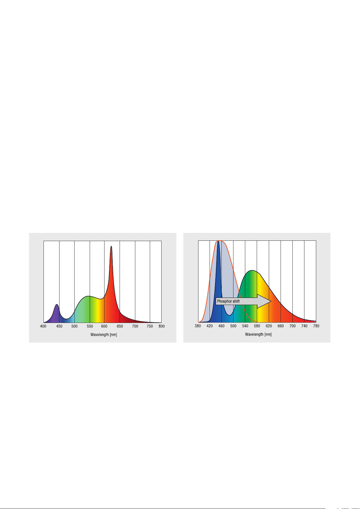
Good red color rendering (R9) and high LED effi ciency are
usually contrary targets because generating red light out of
a blue wavelength generates maximum losses.
OPTICAL CONSIDERATIONS
HD concept
With the HD concept, effi cient red light from direct red-
emitting LEDs is mixed with effi cient, greenish white. In this
way, PrevaLED
®
Core HD light engines provide very high CRI
(>90) with excellent R9 and the highest levels of effi ciency.
Pure phosphor conversion on CoB
Using the pure phosphor conversion with PrevaLED
®
Core
ECO Z2, color rendering quality higher than CRI 80 can be
achieved while providing a very homogeneous light output.
15
Page 16

OPTICAL CONSIDERATIONS
2.1. Refl ector
PrevaLED ® Core ECO Z2PrevaLED ® Core HD
PrevaLED® Core light engines are ideally suited for use with
refl ectors. The HD version of the light engines emit light at
>130° FWHM (full-width, half-maximum) exceeding the
FWHM of Lambertian emitters (120°) which allows shaping
and controlling the emitted light more effectively while at the
same time mini mizing the size of the required refl ector.
Futhermore, this wide emission also maximizes the luminous
intensity that is achieved from a given refl ector design, as
illustrated on the right.
The illustration below shows that an increasing FWHM signif-
icantly reduces the required height of the refl ector needed for
effi cient beam shaping. A reduced refl ector height can either
be used to decrease the overall luminaire height or to im-
prove the thermal performance of the luminaire by increasing
the available height for the heat sink.
An even light emitting surface due to CoB technology of
PrevaLED
®
Core ECO Z2 with great homogeneity eliminates
the need to use diffuser material. A smaller light emitting sur-
face (LES) and a refl ector positioning closer to LES enables a
better optical handling. A beam angle of 10° or even less is
possible with PrevaLED
Luminous intensity curves from a refl ector for different light source FWHMs
®
Core ECO Z2.
16
Page 17

2.1.1. Refl ector design
OSRAM provides mechanical (3D fi les) and optical simulation
data (ray fi les) to support customized refl ector designs.
These data are available upon request through your sales
partner and for public download at:
www.osram.com/prevaled-core.
OPTICAL CONSIDERATIONS
In addition, refl ector design support and off-the-shelf
components are, for example, available through the
following manufacturers:
ACL-Lichttechnik GmbH
+49 2173 9753 0
info@refl ektor.com
www.refl ektor.com
For PrevaLED
®
Core ECO Z2 refl ector 5020 KFAC (ACL,
Alux·Luxar GmbH & Co. KG
+49 2173 279 0
sales@alux-luxar.de
www.alux.de
71.5 mm diameter, 2x8.53° beam angle) and 113309010101
(Jordan, 108 mm diameter, 2x23° beam angle) can be sug-
gested.
Additional diffusing material may be used to optimize homo-
geneity within the application, the best effi ciency is achieved
by placing diffusing material on top of the refl ector. Diffusing
materials may be chosen according to the luminaire‘s design.
Jordan Refl ektoren GmbH & Co. KG
+49 202 60720
info@jordan-refl ektoren.de
www.jordan-refl ektoren.de
In reference designs, the use of Evonik material Plexiglas
®
0D010df with a thickness of 2 mm and with a transmission
of 89.6 % resulted in a good performance. Other materials
can of course also be used, such as Altuglas 145.10000,
for example.
Further support for any Plexiglas
Evonik Roehm GmbH
+49 6151 18 01
info-rohmax@evonik.com
www.evonik.com
www.plexiglas.de
®
material is available at www.ledlightforyou.com or, for example, through the following contacts:
Altuglas International
+33 1 78 66 23 00
www.altuglas.com
Sabic Innovative Plastics
+31 164 29 29 11
www.sabic-ip.com
17
Page 18
OPTICAL CONSIDERATIONS
PrevaLED ® Core HD PrevaLED ® Core ECO Z2
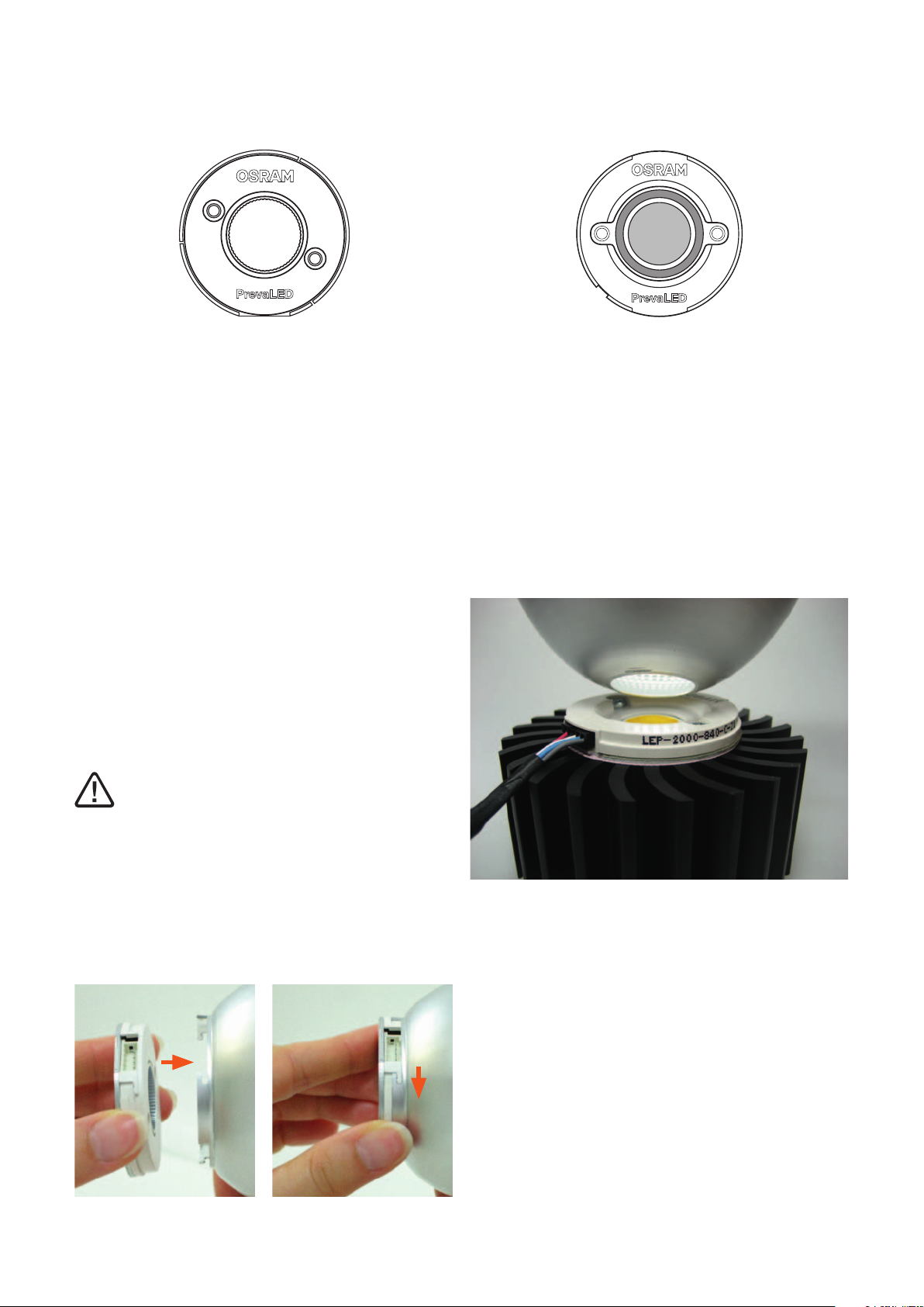
2.1.2. Refl ector mounting HD version
PrevaLED® Core light engines offer multiple mounting points
for a refl ector. For the HD-type light engines, a refl ector can
be centered on a groove along the outer edge of the light
engine as well as in a groove of approximately 23 mm diameter
in the center of the light engine. The 800 lm package provides
an additional groove of approximately 18.10 mm diameter in
the center of the light engine. The inner groove of the light
engines allows mounting the refl ectors as close as possible to
the LED array. Independent of location, all grooves provide a
bayonet-type locking mechanism so that a refl ector can be
fi xed to the light engines. The images below show an example
of a refl ector as it is locked in place, illustrating the location
of the mounting grooves.
By using the provided mounting grooves, the requirements
of IEC 60598 concerning the light engine level are met. For
further details, see the section: 3.1. Safety requirements.
Please note that excessive force on the housing of
the light engine when not mounted to a heat sink can
damage the light engine or housing. Only connect or discon-
nect a refl ector when the light engine is securely mounted to
a heat sink.
2.1.3. Refl ector mounting ECO Z2 version
Z2 ECO light engines employ a different geometry of the
housing. These light engines provide a well-defi ned optical
contact area (OCA) that can be used to center and guide a
refl ector with the light engine. Mounting and mechanical
support of the refl ector in this confi guration must be provided
by the luminaire body or through dedicated refl ector mount-
ing structures. 3D fi les of the light engines and design sup-
port are available upon request.
The locking mechanism is intended for fi xation of the refl ec-
tor only. Do not apply excessive forces or weight as this may
damage the mounting mechanism.
18
Page 19

2.2. Light color stability
The nominal CCT of the light engine is 2,700 K, 3,000 K,
3,500 or 4,000 K, depending on type of light engine. The
light engines provide a module-to-module variation less than
3 (HD) or 4 (ECO Z2) SDCM maximum on Planck around
these color targets, depending on type. The higher light color
stability for HD types is achieved by active electronic control.
OPTICAL CONSIDERATIONS
19
Page 20

ELECTRICAL CONSIDERATIONS
3. Electrical considerations
3.1. Safety requirements 3.2. Wiring information
All OPTOTRONIC® OTp devices intended for operating
PrevaLED® Core light engines are SELV-equivalent devices
with an output voltage of < 120 V
The design of the light engines ensures that the requirements
of IEC 60598 are met for the light engine itself. In particular,
the LEDs on the light engine need not be covered to fulfi ll the
requirements of IEC 60598.
Due to its construction, the light engine can be mounted
directly on an exposed heat sink without further galvanic
insulation.
It remains the responsibility of the luminaire manufacturer to
provide clearance and creepage distances for the luminaire
for an operating voltage of < 120 V
line voltage where applicable.
.
DC
for the light engines and
DC
The recommended wire cross section on the primary side of
the OPTOTRONIC
tion between the OPTOTRONIC
should be established by using the cable kit available for
order in 400 mm and 800 mm length.
The cable material is UL-listed (UL E52653, UL E48762,
UL 10368) and fulfi lls fl ammability requirements UL 94 V-0
and UL VW-1. The inner wires are approved for 105 °C, the
outer cable material for 125 °C.
The maximum diameter of the cable is 5 mm, additional
details on the dimensions of the cable kit are given in the
illustrations on the right page.
For support on customizing cable lengths or construction,
you can use the manual cramping tool from Hirose Electric
or contact your sales partner.
The cable for PrevaLED
connectors and shows a white ring at the light engine side
of the cable (to be confi rmed).
®
OTp ECGs is 0.5–1.5 mm2. The connec-
®
®
ECG and light engine
Core ECO Z2 has two different
20
Page 21

Components of the connection cable between LEP and OTp
*) The picture shows the crimped status of the contact.
**) The crimping socket is produced by Hirose Electric: www.hirose.com
ELECTRICAL CONSIDERATIONS
5-pole plug* (crimping socket**)
DF3-5S-2C
Terminal (straight pin header)
DF3A-5P-2DSA
Pin 1
Pin 2
Pin 3
Pin 4
Pin 5
PIN assignment of connector
LED+
LED-
Aux. voltage
Sense comm.
Aux. gnd.
21
Page 22

ELECTRICAL CONSIDERATIONS
3.3. Wiring in class I and class II luminaires 3.4. Optional cable clamp
Depending on the design of the luminaire according to
class I or class II requirements, a protective earth connection
can be established for the OPTOTRONIC
®
ECG.
For class II luminaires standards can be fulfi lled using a cable
clamp. The functional earth may be connected to the ECG to
improve the EMI behavior.
See illustrations below for these requirements.
As the power supplies are SELV-equivalent, no additional
galvanic insulation has to be provided for the light engine.
For OPTOTRONIC
®
OTp 35 and OTp 45 types, an optional
cable clamp is available for order. This cable clamp can be
snapped onto the ECG and thus converts it into an ECG
suitable for independent installation with strain relief.
When using this cable clamp, luminaire design according
to IEC 60598-1 class I and class II is possible. Connection of
protective earth as detailed above must be observed.
Please also note the installation requirements as supplied
with the cable clamp.
Mains
nc
GND
5 V
Light engine
Class I
connection
Earth connection is mandatory in class I luminaires and
improves EMI compliance according EN 55015.
22
Mains
Do not connect
nc
GND
5 V
Light engine
Class II
connection
In class II luminaires do not connect earthing terminal.
Page 23

3.5. ESD protection of light engines 3.6. Ingress protection
ELECTRICAL CONSIDERATIONS
PrevaLED® light engines require special ESD-safe handling
procedures in a production environment. Please refer to the
datasheet for specifi c recommendations.
PrevaLED® Core light engines and matching
OPTOTRONIC® OTp devices are intended for use
in dry locations.
For operation in damp/wet or dusty environments, the
luminaire manufacturer must ensure suitable installation
and protection of light engines and ECG.
You can use up to 15 OTp (35/45) on one 16-A circuit
breaker.
23
Page 24

THERMAL CONSIDERATIONS
4. Thermal considerations
Proper thermal design of an LED luminaire is critical for
achieving best performance and ensuring long lifetime of all
components. While PrevaLED
with minimal thermal losses possible, a substantial amount
of the light engine power as specifi ed (please refer to: 1.2.2.
Technical data) must be dissipated through the backside of
the light engine.
Depending on the application and the light engine chosen,
passive cooling can be achieved. In critical applications
(e. g. small available heat sink size in combination with high-
power light engines), active cooling may be needed. Active
cooling combines a heat sink with a fan or a similar device to
maximize the cooling power out of a given heat sink.
Active cooling systems:
Nuventix www.nuventix.com
Sunon www.sunoneurope.com
Cooler Master www.coolermaster.com
AVC www.avc-cooling.com
Heat sinks:
Fischer Elektronik www.fi scherelektronik.de
Pinbloc www.pinbloc.de
Aavid Thermalloy www.aavidthermalloy.com
Meccal www.meccal.com
Wakefi eld www.wakefi eld.com
R-Theta www.r-theta.com
Cool Innovations www.coolinnovations.com
Radian www.radianheatsinks.com
®
Core light engines operate
Thermal interface materials:
Laird www.lairdtech.com
Kunze Folien www.heatmanagement.com
Aavid Thermalloy www.aavidthermalloy.com
Chomerics www.chomerics.com
Bergquist www.bergquistcompany.com
Wakefi eld www.wakefi eld.com
Arctic Silver www.arcticsilver.com
Dow Corning www.dowcorning.com
Thermagon www.thermagon.com
Kester www.kester.com
Thermafl o www.thermafl o.com
MG Chemicals www.mgchemicals.com
Electrolube www.electrolube.com
Kerafol www.kerafol.de
4.1. Thermal interface material and other accessories
When mounting PrevaLED® Core within a luminaire it is highly
recommended to use thermal interface material between the
light engine’s backside and the luminaire housing. Either
paste or foil can be used. The material has to be as thin as
possible and should meet the desired conduction between
the light engine surface and the luminaire housing surface.
For this purpose, the planarity and roughness of the sur face
should be optimized. Pads made of Kerafol material with a
diameter of 50 mm and with appropriate mounting holes can
be ordered through the Alfatec company: www.alfatec.de.
The lists below show a selection of suppliers of different
cooling solutions and thermal accessories. The light engine
system has been tested, for example, with coolers from
Nuventix (SynJet
Light Cooling system: TA004-10003).
®
Spotlight Cooler 38W) and Sunon (Spot-
Heat pipes:
DAU www.dau-at.com
MB Electronic AG www.mb-electronic.de
Simulation software:
SolidWorks www.solidworks.com
Flotherm www.mentor.com
Comsol www.comsol.de
Thermal probes:
OMEGA www.omega.de
B+B Thermo-
Technik www.bubthermo.de
24
Additional partners for thermal support can also be found at
OSRAM’s LED Light For You network: www.ledlightforyou.com.
Page 25

4.2. Heat sink size
For the selection of a suitable heat sink, several consider-
ations regarding thermal resistance have to be made.
Below, you can fi nd the defi nition of the thermal resistance
concerning the direct conduction through solid material:
THERMAL CONSIDERATIONS
Material
Copper
Aluminium
Brass
Steel
Stainless steel
Glass
Wood
Air (dry at 1,013 mbar,
no convection)
[W/(m · K)]
380–401
200–220
120
42–58
15
1
0.13–0.18
0.0256 at 20 °C
Very good cooling
Bad/no cooling
R
thcond
=
L
A
·
cross
A
L
: Spec. heat conductance value [W/(m · K)]
L: Length through the material in fl ow direction [m]
A: Material cross section/surface of the heat sink [m
2
]
25
Page 26
THERMAL CONSIDERATIONS
For satisfying heat transfer and good cooling, the surface of
the used heat sink material also has to be taken into consid-
eration. Depending on the location of the particular applica-
tion, it could be an advantage to use black anodized heat
sinks to get the best heat transfer to the ambient air.
Within applications with high surrounding heat radiation, it
would on the other hand be an advantage to have a high
refl ective material to avoid collecting additional heat from the
environment.
Within common applications such as normal downlight appli-
cations within recessed ceilings, a black anodized heat sink
would be suffi cient. Below, you fi nd an overview of some
materials with different surfaces:
Material
Gold, polished
Aluminium plate,
rolled, blank
Aluminium,
black anodized
Aluminium, lacquered,
matt black
* Temperature of the material at which the emission ratio was measured
Emission
ratio ⑀
0.018 130
0.040 170
0.022 25
0.600 40
0.970 80
Temperature *
[°C]
Bad/no cooling
Very good cooling
For the optimization of the radiation, special lacquers with a
high emission ratio, which are typically used for radiators, are
available on the market.
26
Page 27

THERMAL CONSIDERATIONS
To give a short guideline for the selection of a suitable heat
sink, the following steps are generally necessary:
Defi ne boundary
conditions
Estimate heat sink thermal resistance
Total power dissipation of the light engine
Max. ambient temperature T
Max. reference temperature Tc according to lifetime requirements
R
thCA
on light engine level
Use the estimated R
Select heat sink
and examine the performance curve in the supplier catalog.
thermal resistance
Check the design with thermal measurements as soon as physical
prototypes are available.
=
T
- T
C
P
Light engine
amb
A
as a target for a possible heat sink profi le
thCA
27
Page 28

THERMAL CONSIDERATIONS
PrevaLED® Core on extruded-profi le heat sink in downlight orientation
The diagram above can be used to estimate the cooling
performance of a given heat sink size or determine the
approximate size of heat sink required for given ambient
temperatures. Simulations were done without any airfl ow
turbulences, just within free convection.
As an example for heat sinks with 0.25 m² and 0.5 m², the
diagram indicates that a delta of approximately 22 °C or
14 °C respectively can be expected for the LEP-2100
light engines’ T
point as compared to the ambient tempera-
c
ture. The simulations on the next page highlight this result.
In reverse direction, given the maximum Tc temperature of
65 °C of the light engines and an ambient temperature of
45 °C, the resulting temperature difference of 20 degrees
can be used to fi nd the approximate needed heat sink size
for stable operation. For the given temperatures and an
LEP-2100 light engine, this is a heat sink with a surface of
approximately 0.3 m².
Note: The estimations on these two pages are for illustration only. In any case, the realized application has to be tested by a Tc measurement.
28
Page 29
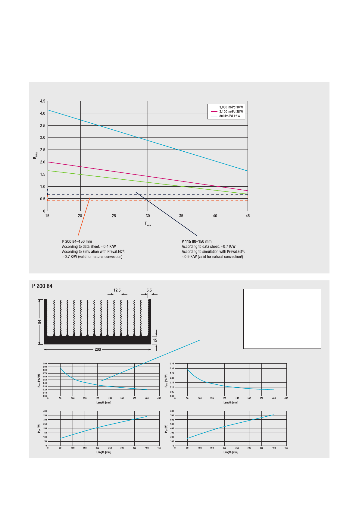
THERMAL CONSIDERATIONS
This diagram shows the correlation between a given ambient temperature and
the resulting R
ferent light engines. The two Meccal extrusion profi les are also marked in the
diagram. From these data, one can estimate the heat sink R
ambient temperatures.
for Tc max. for the dif-
thCA
for different
thCA
P 200 84–150 mm
According to data sheet:
~0.4 K/W (natural convection)
Heat sink P 200 84
Length [mm] 200
Weight [kg/m] 17.70
R
[°C/W] 0.34
TH,N
P
[W] 205
d,N
R
[°C/W] 0.113
TH,F
P
[W] 440
d,F
Note: The estimations on these two pages are for illustration only. In any case, the realized application has to be tested by a Tc measurement.
29
Page 30
THERMAL CONSIDERATIONS
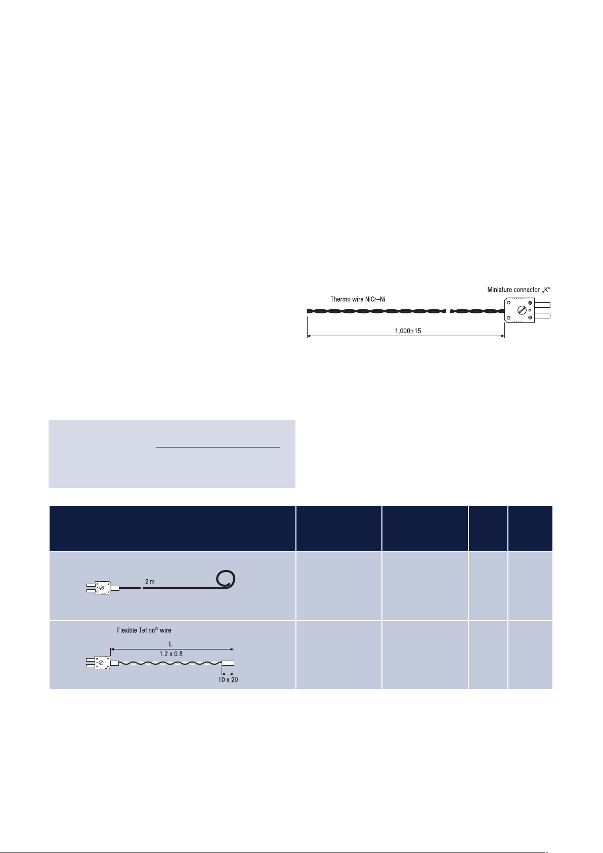
4.3. Tc measurement
After mounting the light engine in the luminaire, the Tc tem-
perature (case temperature) has to be measured within the
planned ambient and operation conditions.
Therefore, a thermal probe has to be fi xed at the T
either by gluing, soldering or welding. Examples of recom-
mended thermal couples are shown below.
With this Tc, you can determine your heat sink solution:
point,
c
(Tc-Ta)
R
heat sink =
th
Thermal power
(PrevaLED® light engine)
K-type thermocouple with miniature connector
Description Temperature [°C] Length
[mm]
Thermal probe -10…+100 2,000
cable
Adhesive foil probe -50…+250 1,000
wire
T90
20
12
All fi gures in mm
30
Page 31
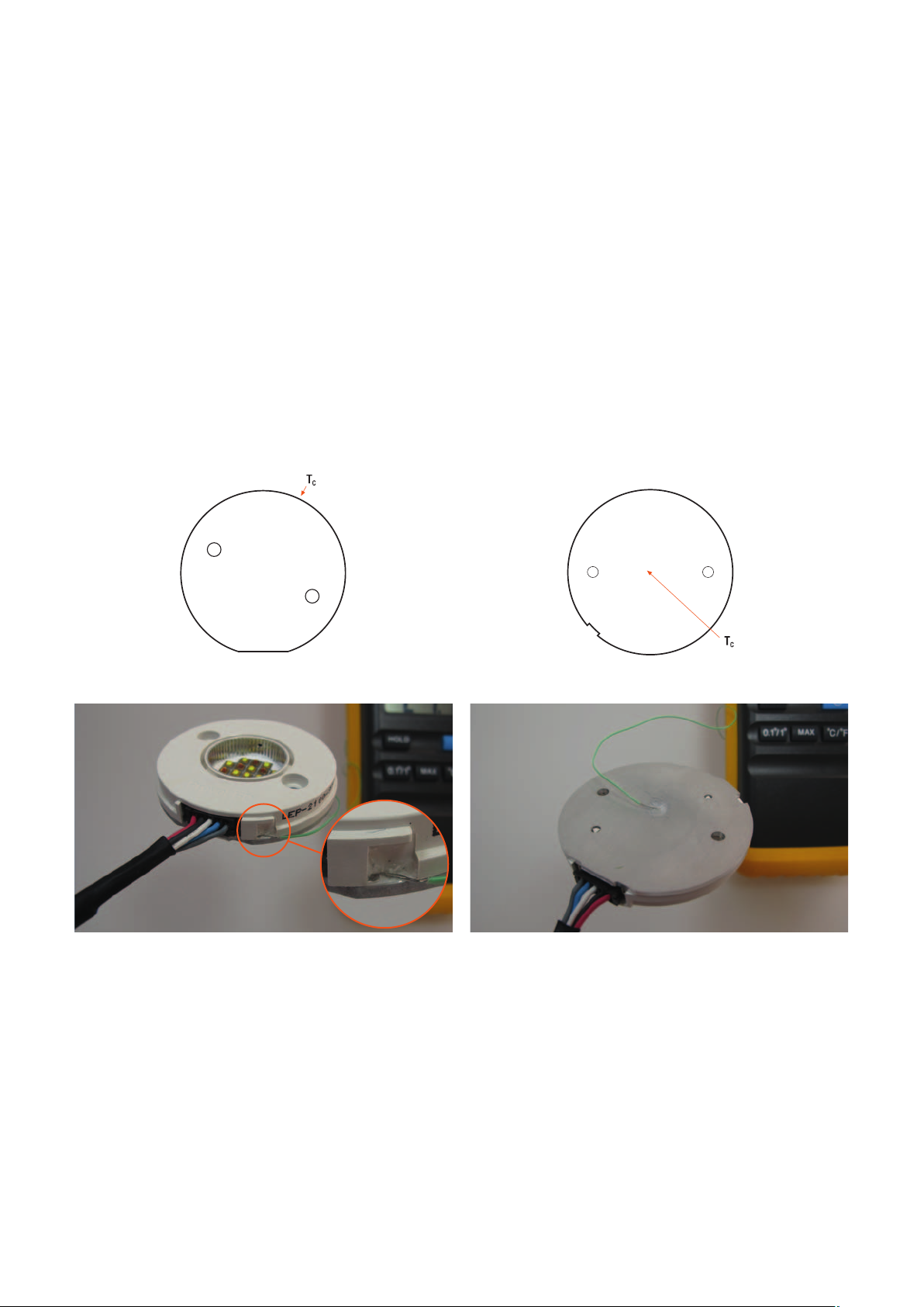
PrevaLED® Core HD PrevaLED® Core ECO Z2
THERMAL CONSIDERATIONS
Tc is measured on the side of the light engine Tc is measured in the center of the back side of the light engine
Please measure the case temperature (Tc) for PrevaLED® Core
HD on the side of the light engine. This can be achieved by
gluing the tip of the thermal couple right from above on the
PCB within the recess as shown on the picture.
Please measure the case temperature (T
Core ECO Z2 in the center of the back side of the light
engine. This can be achieved by a thin, milled channel or a
drilled hole.
) for PrevaLED®
c
Both methods of measurement on the specifi c light engines will assure a precise thermal interface within the thermal path from
the heat source to the ambient air.
31
Page 32

THERMAL CONSIDERATIONS
4.4. Thermal simulation
Two examples of heat sink simulations:
T heat sink:
46…49 °C
Attention: TJ is in any case higher than 60 °C
T ambient: 25 °C
Surface area ~ 0.25 m
TC: 47 °C
T heat sink:
38…41 °C
T ambient: 25 °C
Surface area ~ 0.5 m
2
(P 115 80 Meccal)
2
(P 200 84 Meccal)
Attention: T
®
PrevaLED
LEP-2100 on extruded-profi le heat sink – 150 mm in downlight orientation
32
is in any case higher than 60 °C
J
T
: 39 °C
C
Page 33

THERMAL CONSIDERATIONS
Thermal model description: PrevaLED® Core HD Thermal model description: PrevaLED® Core ECO Z2
Step-fi les for thermal simulation are available on
www.osram.com/prevaled-core.
4.5. ECG thermal considerations
The installation of the ECG must ensure that the maximum
temperature at the T
thermal considerations for OPTOTRONIC
found in the technical guide for OPTOTRONIC
at www.osram.com/optotronic.
is not exceeded. Further details on
c
®
devices can be
®
, available
33
Page 34

MECHANICAL CONSIDERATIONS
5. Mechanical considerations
5.1. Light engine dimensions
The illustrations below provide futher details on the dimensions
of the available PrevaLED® Core light engines. 3D fi les are
available on our website: www.osram.com/prevaled-core.
Please apply no pressure on LED/LES (light-emitting surface).
Handle with care!
kg
34
Page 35

PrevaLED® Core HD PrevaLED® Core ECO Z2
MECHANICAL CONSIDERATIONS
All fi gures in mm (except where noted otherwise)
Lumen
stacks
[lm]
Inner ∅
[mm]
3000
(2100 for Core HD)
2000
21 24
1500
800
16.3 19.15 cat. LES9 8.6 A 13.5
PrevaLED
®
Core HD ECO Z2
Locking
ring ∅
[mm]
Category
LES OCA
∅
[mm]
Category
cat. LES23 22 D 26
cat. LES19 15.75 B 19
Inner ∅
[mm]
Outer ∅
[mm]
28.5 4
Height
[mm]
35
Page 36

MECHANICAL CONSIDERATIONS
5.2. ECG dimensions
ECG dimensions are also given in
the section: 1.2.2. Technical data.
h
OTp DALI 25
l
1
l
OTp 15 OTp DALI 25 All OTp 35 and OTp 45 types
b
Detailed mechanical drawings and 3D fi les are available
on our website.
• Housing material of these devices is PBT and complies
with UL 94 V-0.
• For input wiring, the housing provides push-in terminals.
• It is recommended to use washers when mounting the
ECGs to the luminaire.
All fi gures in mm
36
Page 37

5.3. Light engine mounting
PrevaLED® Core light engines are mounted to a heat sink
with two M3 screws through the mounting holes within the
light engine. The mounting holes are reinforced with metal
bushing, providing additional strength for a reliable and ther-
mally high-performing connection.
MECHANICAL CONSIDERATIONS
Depending on the thermal interface material and contact
surface conditions, the necessary screwing torque can vary.
Good experiences were made with a range of 0.4 to 0.8 Nm,
higher torque levels do not necessarily lead to signifi cantly
better heat transfer to the heat sink, but may lead to damage
of the light engine.
The recommended counter sink diameter of the mounting
holes for good thermal performance is 3.5 mm maximum.
A bigger counter sink can lead to mechanical deformation of
the PCB and a reduction of heat transfer into the heat sink.
When mounting the light engine with self-cutting screws, an
additional torque may be needed to prepare the thread.
In reference designs, good mounting results were achieved
with EJOT ALTracs.
Due to a large number of possible combinations of thermal
interface material, heat sinks and screws above recommen-
dation should be carefully checked for each individual design
to maximize heat transfer between the light engine and the
heat sink. Optimal mounting can lead to a lower operating
temperature of the light engine and to an improved perfor-
mance of the system.
PrevaLED ® Core HD
∅ 35
®
PrevaLED
Core ECO Z2
∅ 3.3
45°
All fi gures in mm (except where noted otherwise)
37
Page 38

FIXATION IN A LUMINAIRE (EXAMPLE)
6. Fixation in a luminaire (example)
To get a better understanding of the light engine concept
and the design of a luminaire, the following pages will lead
through an exemplary mounting into a demonstrator using
the 800 lm light engine PrevaLED
On the fi rst picture, you can see the different components
of the complete system:
®
.
• Housing (acts as heat sink)
• Refl ector
• Cover
• Decorative ring
• Mounting ring
• Main connection wire
• Cable kit
• Thermal interface material
• Light engine
As a fi rst step, the thermal interface material has to be
applied within the light fi xture housing and/or heat sink.
1
2
3
38
4
Page 39

6.1. Preparation
After applying the thermal interface material, the light engine
has to be fi xed to the surface. For mounting instructions and
screw selection, please see the instruction in chapter:
5.3. Light engine mounting.
FIXATION IN A LUMINAIRE (EXAMPLE)
To ease the centering of the light engine, small plastic sticks
or pins can be inserted into the screw holes in the heat sink
to guide the light engine into the right place. After centering,
the guiding pins can be removed and substituted by the
screws.
5
6
7
8
39
Page 40

FIXATION IN A LUMINAIRE (EXAMPLE)
6.2. Wiring and refl ector/cover
To connect the light engine to the power supply, the suitable
cable kit should be used. To get the connector easily into the
housing, a through hole with a minimum diameter of 10 mm
is suggested.
Once the light engine is connected, the refl ector can be
attached to the housing and the diffuse cover can be placed
on top of the luminaire.
Both components have to be properly centered above the
light engine.
9
11
12
13
40
10 14
Page 41
FIXATION IN A LUMINAIRE (EXAMPLE)
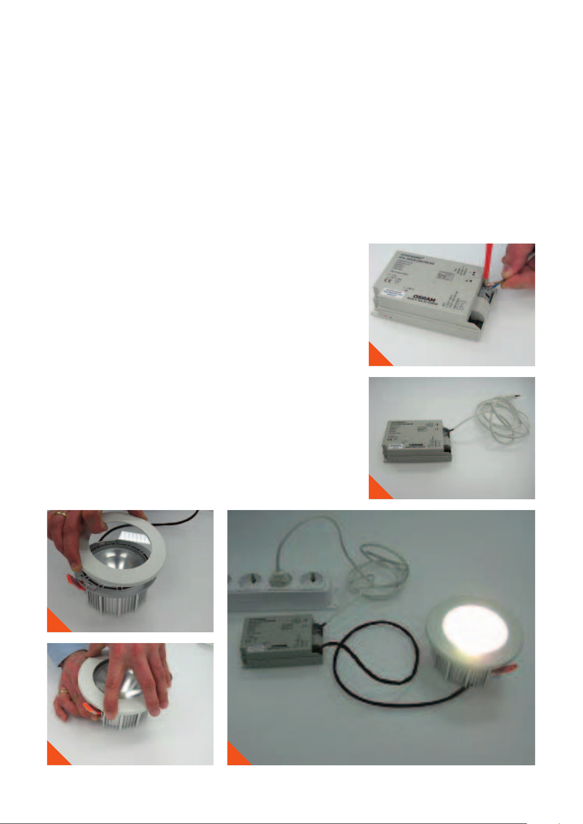
6.3. Commissioning PrevaLED
After the fi xation of the mounting ring, the optional decora-
tive ring can be put into place.
As an example for an electrical connection within a class-II
installation, the two wires for the main connection have to be
applied to the OPTOTRONIC
In a class-I installation, the protective earth has to be
connected in addition.
Finally, the complete system can be connected to the mains
and powered up.
®
®
power supply.
17
18
15
16
19
41
Page 42

NORMS AND STANDARDS
7. Norms and standards
7.1. Standards for PrevaLED
PrevaLED® complies with the following standards:
LED modules safety: IEC 62031
DIN EN 62031
Connectors for LED modules: IEC 60838-2-2
Photobiological safety: EN 62471:2008 (CIE S009): Depending on type
Electromagnetic compatibility: DIN EN 55015
DIN EN 61547
DIN EN 61000-3-2
DIN EN 61000-3-3
Ingress protection: IP 20
Vibration, shocks, tensile strength: IEC 60068-2-6
IEC 60068-2-27
IEC 60068-2-21
®
42
Page 43

NORMS AND STANDARDS
7.2. Power supply standards and features applicable to PrevaLED
Safety:
Performance:
Radio interference:
Harmonic content:
Immunity:
Temperature range: See corresponding value within the datasheet
Galvanic insulation between
primary and secondary side:
No-load proof: Yes
Short circuit proof: Yes
Overload protection: Automatic shutoff, reversible
Overheating protection: Automatic shutoff, reversible
Connection, primary: For OTp 15 HD: screw-terminals
IEC 61347-1, IEC 61347-2-13
IEC 62384
EN 55015 (A1: 2007)
IEC 61000-3-2
IEC 61547
3 kV
rms
For OTp 35 HD and OTp 45 HD: push-in terminals
®
2
Cross section, primary: 0.5 mm
Connection, secondary: 5-pin connector, for use with cable kit
Cross section, secondary: For use with cable kit
Dimensions (L x W x H): 123 x 79 x 33 mm for all OTp 35 and all OTp 45
109 x 50 x 35 mm for OTp 15 HD
Approvals:
– 1.5 mm
0 i
2
]
43
Page 44

NORMS AND STANDARDS
7.3. Interchangeability of LED light engines 7.4. Photobiological safety
The Zhaga Consortium (consortium for the standardization of
LED light engines) aims to make the LED light sources (“LED
light engines”) manufactured by different companies inter-
changeable. Zhaga is a global cooperation with participation
by luminaire manufacturers, lamp manufacturers, LED mod-
ule makers, and companies that supply the lighting industry.
Interchangeability of LED light engines is achieved by speci-
fying the interfaces for a variety of application-specifi c light
engines. Zhaga interface specifi cations cover the physical di-
mensions, as well as the photometric, electrical and thermal
behavior of each LED light engine.
The Zhaga consortium was established in February 2010.
More than 100 companies have joined the Zhaga Consor-
tium. The members meet every 6–9 weeks in Asia, the USA,
or Europe. In June 2011, the Zhaga Consortium approved
the second light engine specifi cation. This is the specifi cation
for the interfaces of a spotlight engine.
PrevaLED
®
light engines were tested regarding the risk group
defi nition within EN 62471: 2008. According to this standard,
the following tables show the risk group defi nitions and test
results of the different light engines.
All PrevaLED
®
Core light engines (with and without PreMix)
have to be classifi ed according to EN 62471-1 in risk group 1
(RG 1). In RG 1, in absence of UV and IR radiation, no label-
ing is required (TR 62471-2).
44
Page 45

NORMS AND STANDARDS
LEP-3000 3,000 K
Spectral radiance and local BLH radiance see below.
Maximum permissible BLH dose (EN 62471) 1 MJ/(m
2
sr)
Maximum blue light effective radiance in
a fi eld of view corresponding to 1.7 mrad
BLH (1.7 mrad) 28,169 W/(m2sr)
Maximum exposure time 36 s
The maximum exposure time related to 1.7 mrad is larger than 10 s.
Therefore, the risk group classifi cation may be determined using a
fi eld of view related to 11 mrad.
Maximum blue light effective radiance in
a fi eld of view corresponding to 11 mrad
BLH (11 mrad) 8,502 W/(m2sr)
Maximum exposure time 118 s
Risk group classifi cation RG 1
LEP-2100 3,000 K
Spectral radiance and local BLH radiance see below.
Maximum permissible BLH dose (EN 62471) 1 MJ/(m
2
sr)
LEP-3000 4,000 K
Spectral radiance and local BLH radiance see below.
Maximum permissible BLH dose (EN 62471) 1 MJ/(m
2
sr)
Maximum blue light effective radiance in
a fi eld of view corresponding to 1.7 mrad
BLH (1.7 mrad) 49,583 W/(m
2
sr)
Maximum exposure time 20 s
The maximum exposure time related to 1.7 mrad is larger than 10 s.
Therefore, the risk group classifi cation may be determined using a
fi eld of view related to 11 mrad.
Maximum blue light effective radiance in
a fi eld of view corresponding to 11 mrad
BLH (11 mrad) 12,870 W/(m
2
sr)
Maximum exposure time 78 s
Risk group classifi cation RG 1
Maximum blue light effective radiance in
a fi eld of view corresponding to 1.7 mrad
BLH (1.7 mrad) 14,412 W/(m2sr)
Maximum exposure time 69 s
The maximum exposure time related to 1.7 mrad is larger than 10 s.
Therefore, the risk group classifi cation may be determined using a
fi eld of view related to 11 mrad.
Maximum blue light effective radiance in
a fi eld of view corresponding to 11 mrad
BLH (11 mrad) 3,855 W/(m2sr)
Maximum exposure time 259 s
Risk group classifi cation RG 1
45
Page 46

www.osram.com/prevaled-core
Global presence.
OSRAM supplies customers in 148 countries.
•
85 companies and sales offi ces for 122 countries
•
26 countries served by local agents or OSRAM GmbH, Munich
OSRAM associated companies and support centers:
Albania
Argentina
Australia
Austria
Belarus
Bosnia-Herzegovina
Brazil
Bulgaria
Canada
Chile
China
Colombia
Croatia
Czech Republic
Denmark
Ecuador
Egypt
Estonia
Finland
France
Georgia
Germany
Great Britain
Greece
Hungary
India
Indonesia
Iran
Italy
Japan
Kazakhstan
Kenya
Korea
Latvia
Lithuania
Macedonia
Malaysia
Mexico
Moldavia
Netherlands
Norway
Pakistan
Peru
Philippines
Poland
Portugal
Romania
Russia
Saudi Arabia
Serbia
Singapore
Slovakia
South Africa
Spain
Sweden
Switzerland
Taiwan
Thailand
Tunesia
Turkey
Ukraine
USA
Uzbekistan
United Arab Emirates
Vietnam
OSRAM AG
Head Offi ce
Hellabrunner Strasse 1
81543 Munich
Phone +49 (0) 89-6213-0
Fax +49 (0) 89-6213-20 20
www.osram.com
 Loading...