

Page 1
DALI LS/PD BASIC
Vcc LS 0V
NCPDNC
OSRAM
DALI LS/PD
BASIC
DC
C
B
A
D
Light and motion sensor
Fitting instructions
Description
Installation
Purpose and application
The DALI LS/PD BASIC sensor detects the presence of persons and measures the intensity of ambient light.
The sensor is designed for connection to DALI RC BASIC SO
control units and can be installed in luminaires or ceilings.
Function
The sensor measures the brightness in the area requiring
control and transmits the light value to the control unit for the
purpose of keeping it to an adjustable set value by introducing
articial light according to the amount of daylight available. As
the amount of daylight increases, articial lighting is reduced.
The sensor always transmits the detection of movements of
persons to the control unit. After the sensor stops detecting
motion, the control unit switches the luminaires off following an
adjustable delay period.
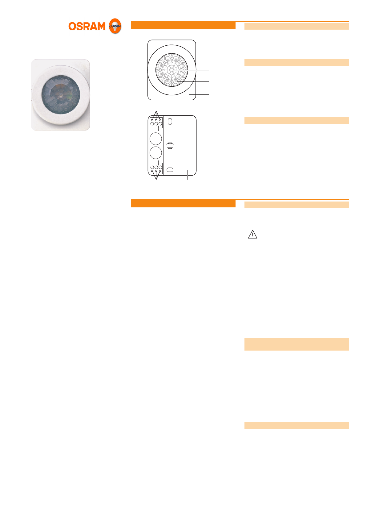
Design
The sensor is made up of the following components:
• Light sensor (A)
• Motion sensor (B)
• Connections (C):
– Supply voltage (Vcc)
– Ground (0V)
– Output for light measurement value (LS)
– Output for motion signal (PD)
• Housing (D)
Safety instructions
The sensor must only be installed and put into operation by
a qualied electrician. The applicable safety regulations and
accident prevention regulations must be observed.
WARNING!
Exposed, live cables or damaged
housing.
Danger of electric shock!
• Only work on the sensor when it is
de-energised.
CAUTION!
Destruction of the sensor and other devices through
incorrect mounting!
• Adhere to the connection diagram.
• Do not exceed the maximum line length.
• When mounting in luminaires, use a UV-resistant
cable.
• Do not route the sensor lines together with DALI
or power supply lines.
• Only connect the sensor to control units of type
DALI BASIC SO.
Attaching the sensor to the
uorescent lamps
Precondition: T5 or T8 lamps with a min. grid of 60 mm.
Determining a suitable installation location (see „Selecting
the installation location“)
Insert the lamp clip into the sensor housing base.
Attach the sensor to the lamp end with the lamp clip to avoid
weighing down the lamp excessively. Minimum distance to
the lampholder due to heat development of the coils: 8 cm.
If necessary, adjust the sensor installation depth to the depth
of the grid luminaire by sliding the lamp clip in or out.
Pull the sensor off of the attached housing base.
Connect the sensor; see the connection diagram.
Attach the sensor to the housing base again.
Attaching the sensor to the ceiling
Determining a suitable installation location (see „Selecting
the installation location“).
Take off the sensor base plate.
Screw the base plate onto the ceiling.
Connect the sensor; see the connection diagram.
Attach the sensor to the base plate.
Page 1 of 2
Page 2
Installation (cont.)
3 m
E
2,5 m
3,5 m
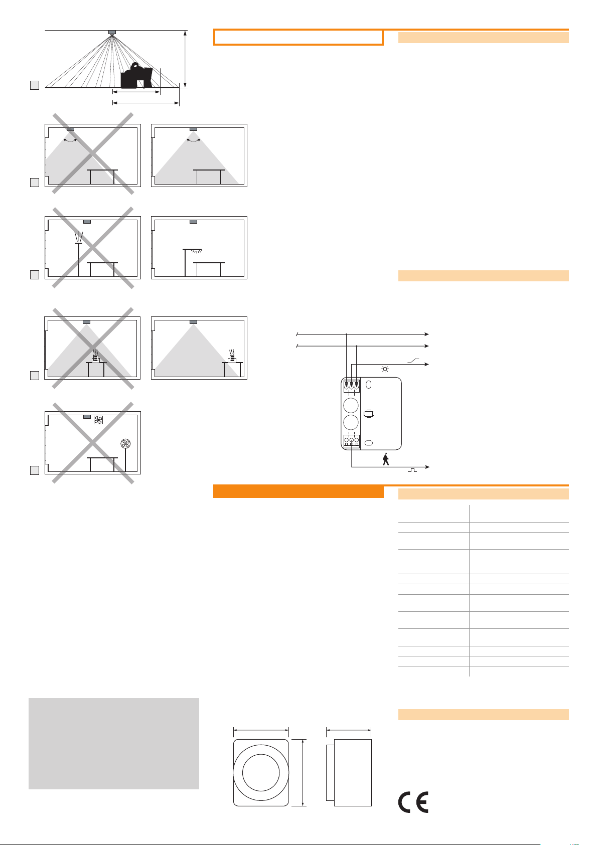
Selecting the installation location
E Optimal mounting height: 2.5 – 3 m. As the mounting height
increases, the detection area increases and sensitivity is
reduced.
F Monitoring cone: entire workplace; not on window surfaces
G Avoid exposure to direct light.
H Place devices that radiate heat outside of the monitoring
cone.
I Avoid drafts (e.g. from ventilators).
100°
100°
F
G
(+)
(-)
Connecting the sensor
K Light measurement value
L Motion signal
Vcc
0V
LS
H
Vcc LS 0V
OSRAM
DALI LS/PD
BASIC
NCPDNC
I
IV 2009
DALI_LS-PD_BASIC_ma0904en_we1.01.indd
OSRAM GmbH
Kunden Service Center
Customer-Service-Center (CSC)
Steinerne Furt 62
86167 Augsburg
Germany
Tel : +49 (0) 1803 677 - 200
(kostenpichtig / charges apply)
Fax.: +49 (0) 1803 677 - 202
www.osram.com
www.osram.de
40503006399492
4050300639949
Appendix
58,5 42
70,5
PD
Technical data
Operating voltage Nominal 10 V DC
Current consumption Max. 3 mA DC
Maximum total line
length
Line connection Screw terminals for single-wire
Operating temperature 0 °C … +50 °C
Operating range Up to 400 lx measured at sensor
Detection area Conical, opening angle approx.
Pollution severity 2 (dry, not conductive, as per
Dimensions
(L x W x H)
Weight Approx. 70 g
Protection type IP 20
Protection class II
(8 – 20 V DC)
100 m
or ne-wire conductors with 0.3 –
1.5 mm²
100°
IEC 664)
58.5 x 70.5 x 42 mm
Dimensioned drawing
Conformity with the relevant EU directives is
conrmed by the CE symbol.
Page 2 of 2
 Loading...