

Page 1
OT EASY 60 II
LED control unit
Operating instructions
Page 2

Page 3

Contents
Safety ..............................................................................................4
General instructions 4
Safety instructions 4
Intended use 4
Description ......................................................................................5
Function and application 5
Function 5
Important denitions 5
Scene, lighting scene 5
Sequence 5
Fade time 5
Cycle time 5
Operating modes 6
Behaviour after a power failure 6
Connections 6
Installation .......................................................................................7
Connecting the control unit 7
Wiring diagram 7
OT EASY 60 input connections 7
Connecting the inputs 8
OT EASY 60 output connections 9
Connecting the outputs 9
Expanding the system 10
Master-slave circuit 10
Procedure 10
Wiring diagram (example of a master-slave circuit) 11
Operation ......................................................................................12
Remote control 12
Activating the operating modes 13
Switching on and off the luminaires 13
Changing the brightness manually 13
Storing and calling up a lighting scene 14
Disabling scene storage 14
Starting and ending the sequencer mode 14
Setting the fade and cycle time 15
Example of a sequence 15
Example of a daylight simulation 16
Troubleshooting 16
Appendix .......................................................................................17
Technical data 17
Applicable standards 18
Dimensions 18
3
Page 4

Safety
Safety
General instructions
The control unit must only be installed and put into operation by a qualied electrician.
The applicable safety regulations and accident prevention regulations must be observed.
Safety instructions
WARNING!
Exposed, live cables.
Danger of electric shock!
• Only work on the control unit when it is de-energised.
CAUTION!
Destruction of the control unit and other devices through incorrect mounting!
• Ensure that the external pushbutton is designed for the mains voltage.
• Do not wire the control and pushbutton lines with an external voltage, especially
not a mains voltage of 230 V.
• Do not exceed the maximum number of connectable components.
• Only use the intended infrared receiver types.
OT EASY 60
Intended use
4
The OT EASY 60 II control unit may only be operated in the operating modes described
in the „Description“ section. All other applications are considered to be inappropriate
use.
If the OT EASY 60 II control unit is not used as intended, there is no guarantee that it
will operate safely.
IV 2009
Page 5

OT EASY 60
Description
Function and application
The OT EASY 60 II LED control unit can be used to implement static and dynamic lighting concepts.
Function
The OT EASY 60 II LED control unit enables the manual and automatic control of up to
four LED luminaire groups on separate channels. Up to 4 x 16 lighting scenes can be
programmed, called up individually or run through cyclically in up to 4 sequences (e.g.
to simulate daylight).
A colored light mixing system can be set up by assigning LED colors to the outputs.
The functions can be executed via a remote control, pushbutton, switch, timer switch,
motion detector or PC, depending on the installation.
Important denitions
Scene, lighting scene
A lighting scene denes the lighting situation in a room or the color resulting from the
mixing of individual LED colors (red, green, blue).
Example 1: Coloured effect lighting
The LEDs have different colors (red, green, blue, white). They are set to different
brightness levels according to the desired shade of color (mixed color of the room
lighting). This mixing color is a lighting scene.
Example 2: Daylight simulation
White LED modules with different colour temperatures of 3300 K and 6500 K in conjunction with red and blue LED modules are suitable for daylight simulation in areas
at a great distance from a window front, ceiling lights and task lighting with variable
colour temperatures. Very slow cross fades are imperceptible to the human eye.
Description
IV 2009
Sequence
A sequence is the automatic retrieval of stored lighting scenes and their cyclic playback.
Fade time
The fade time is the time in which the lighting system changes from one lighting scene
to the next in sequencer mode.
Cycle time
The cycle time is the time in which the daylight simulation system runs through a
complete daylight cycle.
5
Page 6
Description
Easy signal
24 V (+)
CH
1 (R-)
CH
2 (G-)
CH
3 (B-)
CH
4 (W-)
GND
(-)
OT EASY 60
L
N
Operating modes
OT EASY 60 II has three operating modes:
• Lighting control mode: Brightness is adjusted manually, and luminaire groups and
lighting scenes are switched on and off manually.
• Sequencer mode: The stored lighting scenes are called up automatically one after
the other. The fade time between the lighting scenes is adjustable.
• Daylight simulation: The lighting scenes are called up automatically to simulate light
conditions as they change during the course of a day. Lighting scenes and cycle
time (= duration of the „day“) can be adjusted.
Behaviour after a power failure
The LED modules connected to the control unit behave as follows if there is a power
failure:
• Lighting control mode: The last state prior to a power failure is automatically re-
stored.
• Sequencer mode: After the power supply is switched back on, e.g. by a timer
switch, the sequence restarts with scene 1.
• Daylight simulation: After the power supply is switched back on, e.g. by a timer
switch, the simulation restarts with the scene 1.
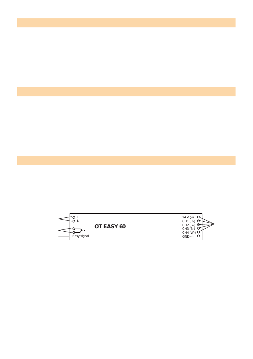
Connections
The control unit has the following connections:
• Mains connection (A)
• Input for external pushbutton (B)
• Input for EASY signal (C)
• Outputs for connecting LED modules (D)
OT EASY 60
6
A
D
B
C
IV 2009
Page 7

OT EASY 60
Infrared receiver
Pushbutton coupler
Max. total line
length 100 m
(optional)
(optional)
Y-connector
EASY PC kit
4
Y-connector
Y-Cconnector
USB
adapter
(optional)
Easy signal
OT EASY 60
R
G
B
PE N L
24 V (+)
CH
1 (R-)CH2 (G-)
CH
3 (B-)
CH
4 (W-)
GND
(-)
L
N
+
Power switch and / or
timer switch (optional)
External
switch
LINEARlight Colormix LED module
Installation
Connecting the control unit
Wiring diagram
Installation
IV 2009
OT EASY 60 input connections
2-wire cable
Short circuit bridge
for control units
Modular cable with
4p4c connector
16 mm
6 mm
6 mm
OT EASY 60 input section
Rubber adapter
L
PRI 220 – 240 V
0/50/60 Hz
N
EASY signal
7
Page 8

Installation
Connecting the inputs
Proceed as follows:
Step Task
1 Connect the 4p4c modular connector of the EASY signal line.
2 Strip the power cable, remove the insulation from the phase and neu-
tral wires and connect to the screw terminals.
3 Connect the line of the external pushbutton to the screw terminals, if
applicable.
4 Mount the cable strain relief: Use a rubber adapter and cable clamp
that are suitable for the power cable diameter; see gure.
5 Insulate the PE conductor, if necessary.
Ø (G) mm Cable strain relief
6 - 7.5
H
G
E
F
7.5 - 8.5
8.5 - 9
OT EASY 60
E Modular cable
F Rubber adapter for modular cable
G Power cable
H Cable clamps
8
IV 2009
Page 9

OT EASY 60
OT EASY 60 output connections
OT EASY 60
output side
24 V (+)
CH1 (R-)
CH2 (G-)
CH3 (B-)
CH4 (W-)
GND (-)
16 mm
6 mm
16 mm
6 mm
Connecting the outputs
Connection lines between the control unit and LED modules:
• Two 3-wire lines (without PE) with the same external diameter
• Max. length: 10 m
• Recommended line diameter:
1.5 mm² (line length < 5 m) or 2.5 mm² (line length > 5 m)
Proceed as follows:
Step Task
1 Strip the 3-wire lines, remove the insulation and connect to the screw
terminals.
2 If the GND wire is unused, insulate it on the side of the LED module.
3 Use cable clamps.
Installation
3-wire cable
(without PE)
IV 2009
K
J Cable clamp
K 3-wire line (2 x)
J
K
9
Page 10

Installation
Expanding the system
Master-slave circuit
In a master-slave circuit, up to 16 DALI EASY or OT EASY control units can be controlled simultaneously via a single remote control, up to two pushbutton couplers or a
single PC.
Note:
Conguration of the master-slave circuit via a PC: see the operating instructions of
the EASY Color Control Software.
Procedure
Proceed as follows to set up a master-slave circuit:
Step Task
1 Disconnect all control units from the mains supply.
2 Connect an external pushbutton to the control unit that is to serve as the
3 For the remaining control units, which operate as slaves, use the bridge
4 Connect the control units via Y-connectors and connect the connection
5 Connect the infrared receiver and pushbutton coupler to one of the
OT EASY 60
master, or leave the input vacant.
at the input for the external pushbutton.
lines with each other.
Y-connectors (optional).
10
Note:
Connect a maximum of four infrared receivers and two pushbutton
couplers.
6 Reconnect all control units with the mains supply.
IV 2009
Page 11

OT EASY 60
OT EASY 60
OT EASY 60
Master
Slave
4
DALI EASY
Slave
PE N L
Y-connector
Y-connector
Y-connector
Y-connector
Y-connector
Easy signal
24 V (+)
CH
1 (R-)
CH
2 (G-)
CH
3 (B-)CH4 (W-)
GND
(-)
+
R
G
B
L
N
Easy signal
24 V (+)
CH
1 (R-)
CH
2 (G-)CH3 (B-)
CH
4 (W-)
GND
(-)
+
R
G
B
L
N
~
~
DA
DA
Easy signal
GND (-)
CH
4+ (W)
CH
3+ (B)CH2+ (G)
CH
1+ (R)
L
N
~
~
DA
DA
~
~
DA
DA
~
~
DA
DA
Power switch and/or
timer switch (optional)
Infrared receiver or
additional EASY components
External
switch
DALI ECG
Red bulb
LINEARlight Colormix LED module
Pushbutton coupler or
additional EASY components
White bulb
Blue bulb
Green bulb
EASY PC Kit or
additional EASY components
Max. total
line length 100 m
DALI ECG
DALI ECG
DALI ECG
LINEARlight Colormix LED module
Installation
Wiring diagram (example of a master-slave circuit)
CAUTION!
Destruction of the control unit and other devices!
• Master-slave connection lines conduct protective extra-low voltage signals; do
not route together with power supply or LED lines.
• Ensure that the master-slave connection lines are sufciently insulated against
the power supply or lamp lines.
IV 2009
11
Page 12

Operation
Operation
Remote control
Note:
These instructions primarily describe the operation via the DALI EASY RMC remote
control. To operate via an EASY PB Coupler, see the separate instructions for the
EASY PB Coupler.
Display
Channel
pushbutton:
Ch1
Ch2
Ch3
Ch4
Start / Time+
Stop / Time -
OT EASY 60
Infrared transmitter
OSRAM
Scene 1
Scene 2
Scene 3
Scene 4
On/Off
Dimming
12
ON
DIP
1 2 3 4
DIP switch
Note:
Additional information on the remote control can be found in the separate operating
instructions of the DALI EASY RMC.
IV 2009
Page 13

OT EASY 60
...
Activating the operating modes
The lighting control mode is always active. The sequencer mode and daylight simulation are activated via the DIP switches in the battery compartment of the remote
control.
Activated operating modes DIP switch setting
Lighting control mode only DIP switch 3 = OFF
Sequencer mode
(incl. lighting control mode)
Daylight simulation
(incl. lighting control mode)
Switching on and off the luminaires
Via short press.
• All LEDs: „On/Off dimming“ button.“.
• LEDs (channels 1 to 4): “Ch1” to “Ch4” buttons.
DIP switch 4 = OFF
DIP switch 3 = OFF
DIP switch 4 = ON
DIP switch 3 = ON
DIP switch 4 = OFF
ON
ON
ON
Operation
Changing the brightness manually
Via long press. Each repeated long key press causes a toggle between increased
brightness and decreased brightness.
• All LEDs: „On/Off dimming“ button.“.
• LEDs (channels 1 to 4): „Ch1“ to „Ch4“ buttons.
Note:
The LEDs of a group are all connected to the same output channel and therefore
have the same brightness.
IV 2009
13
Page 14

Operation
Storing and calling up a lighting scene
„Scene 1“ to „Scene 4“ buttons.
Proceed as follows to store lighting scenes:
Step Task
1 Set the brightness of the luminaire group; see "Changing the brightness
manually".
2 Press the desired button for at least 3 seconds.
3 Conrmation: luminaires ash.
To call up a lighting scene:
Via short press.
Disabling scene storage
Storing of scenes can be disabled by means of the DIP switches in the remote control
or in the pushbutton coupler.
Storing scenes Remote control Pushbutton coupler
Disabled DIP switch 2 = OFF DIP switch 1 = OFF
Enabled DIP switch 2 = ON DIP switch 1 = ON
OT EASY 60
Starting and ending the sequencer mode
Via short press.
• To start and continue the sequencer mode: „Start/time+“ button
• To stop the sequencer mode: „Stop/time−“ button
• To end the sequencer mode: „Ch1“ to „Ch4“, „Scene 1“ to „Scene 4“ or „On/Off dim-
ming“.
14
IV 2009
Page 15

OT EASY 60
Brightness
Setting the fade and cycle time
Set the fade time for the sequencer mode and the cycle time for the daylight simulation.
To increase the time: „Start/Time+“ button
To decrease the time: „Stop/Time−“ button
Proceed as follows:
Step Task
1 Press the button for at least 3 seconds. The time is shown on the display;
see below.
2 Single steps: Short press
Fast forward: Long press
Operating mode Display Interval
Sequencer mode (fade time)
Effect Lighting
Wellness
Long Time
Daylight simulation (cycle time) Hours
Tenths of a second
Seconds
Minutes
Operation
Example of a sequence
IV 2009
Scene 1 Scene 2 Scene 3
Fade time Hold time*
*The hold time is automatically set to 25% of the set fade time.
Scene 1: Ch1 (red) = max.; Ch2,Ch3,Ch4 = min.
Scene 2: Ch2 (green) = max; Ch1,Ch3,Ch4 = min.
Scene 3: Ch3 (blue) = max.; Ch1,Ch2,Ch4 = min.
Scene 4: Ch1...Ch4 = off (is skipped)
Red:
Green:
Blue:
Time
15
Page 16

Operation
Brightness
Example of a daylight simulation
Cycle time 12h. Clock-controlled switch-on at 8 a.m.
90%
80%
Scene 1
50%
8:00 12:00 16:00
Scene 2
Troubleshooting
If you cannot remedy the fault, please contact the Customer Service department of the
luminaire manufacturer.
Fault Cause Remedy
Luminaire does not function
Control unit does not
respond to the remote
control
Control unit does not
respond to the external
pushbutton
Luminaire does not react
as expected to the press
of a button
Sequence in the masterslave mode is not synchronous
OT EASY 60
Scene 3
Scene 4
Cycle time
Time
20:00
No mains voltage present. Check the mains supply
fuses.
Illuminant defective. Replace illuminant.
No mains voltage present. Check the mains supply
fuses.
Illuminant defective. Replace illuminant.
Remote control batteries
are too weak.
Check the display.
Replace the batteries if
necessary.
Remove control is outside
Reduce the distance.
the range of the infrared
receiver.
Wrong IR coding. Check the IR coding.
Infrared receiver is
exposed to direct light.
Shade the receiver or
select another installation
location.
No mains voltage present. Check the mains supply
fuses.
Illuminant defective. Replace illuminant.
Button was pressed too
See "Operation".
long or too short.
No mains voltage present. Check the mains supply
fuses.
Slaves have already been
programmed and have
their own scenes.
Perform a reset and
create the sequence
again.
Slave bridges are missing. Insert the bridges.
16
IV 2009
Page 17

OT EASY 60
Appendix
Technical data
For LED modules With respect to the output conditions:
Operating voltage 220-240 V
Permissible voltage uctua-
tions
Line current, nominal 0.33 A @ 230 V
Output voltage 24 V
Max. module wattage 60 W, distributed over all outputs
Power factor PF > 0.95
Max. losses 8 W @ 230 V
Control signal Digital EASY signal via 4-pin RJ-11 modular con-
Master-slave connection • Max. 100 m total line length
Max. number of connectable
components
Dimming mode PWM (300 Hz)
Dimming range 0-100 %
Operating temperature -20 °C … +50 °C
EASY interface 4-pin modular connection
Secondary side Screw terminals
Max. secondary line length 10 m
Dimensions (L x W x H) 220 x 46.2 x 43.6 mm
Appendix
1 x LINEARlight Colormix Flex (4m),
7 x LINEARlight Colormix, etc.
/ 50-60 Hz
AC
198-264 V
(60 W on only one output is also possible)
nection (4p4c)
AC
DC
• Max. 50 m to pushbutton coupler
• Max. 1 master and 15 slaves are connectable
• Do not route the master-slave connections
together with the power supply or LED lines.
• 4 EASY IR sensors
• 1 EASY pushbutton coupler
• 1 EASY USB adapter
IV 2009
17
Page 18

Appendix
Applicable standards
Safety UIEC 61347
Performance IEC 62384
Radio interference EN 55015, EN 55022
Harmonic content IEC 61000-3-2
Immunity IEC 61547
Dimensions
OT EASY 60
Conformity with the relevant EU directives is conrmed by the CE symbol.
18
IV 2009
Page 19

IV 2009
OT_EASY_60_II_ma0904en_we1.01.indd
OSRAM GmbH
Kunden Service Center
Customer-Service-Center (CSC)
Steinerne Furt 62
86167 Augsburg
Germany
Tel : +49 (0) 1803 677 - 200
(kostenpichtig / charges apply)
Fax.: +49 (0) 1803 677 - 202
www.osram.com
www.osram.de
40083211877966
4008321187796
 Loading...