

Page 1
MULTIeco
A
LN
Control unit
Fitting instructions
Description
L
G B
N
MULTIeco
F
E
Sensor
D
Purpose and application
The MULTIeco control unit controls the lighting at the workplace
and in ofces according to the level of daylight and the presence of persons to increase comfort and save energy.
The control unit can be installed in luminaires (e.g. oor standing luminaires) or in suspended ceilings.
Function
Sensors measure the brightness in the section to be controlled
and switch on the connected luminaires as soon as the level
of daylight is less than an adjustable brightness switching
threshold.
The sensors also detect the presence of people.
When people are no longer present, the connected luminaires
switch off after an adjustable delay period.
Daylight-dependent switching and presence detection can be
activated and deactivated using various operating modes.
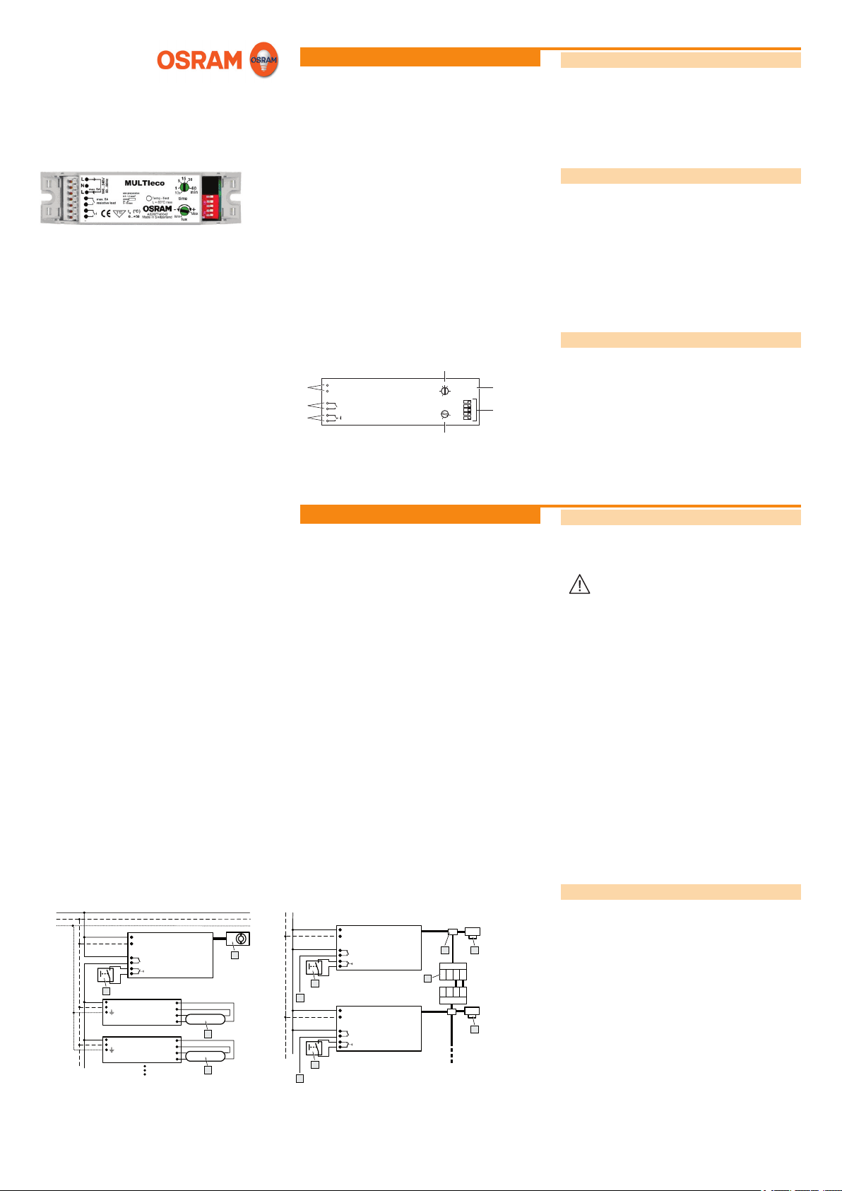
Design
The control unit is made up of the following components:
• Adjusting screw “time” (A): switch-off delay time
• Sensor connection (B)
C
• DIP switch (C)
• Adjusting screw “lux” (D): brightness switching threshold
• Button connection (E)
• Load contact (F)
• Power supply connection (G)
Installation
Safety instructions
The control unit must only be installed and put into operation
by a qualied electrician. The applicable safety regulations and
accident prevention regulations must be observed.
WARNING!
Exposed, live cables or damaged housing.
Danger of electric shock!
• Only work on the control unit when it is deenergised.
CAUTION!
Destruction of the control unit and other devices
through incorrect mounting!
• Do not operate any other control units on the
control line.
• Use the LMS CI BOX mounting kit for ceiling
installation.
• Ensure that the external pushbutton is designed
for the mains voltage.
• Do not wire the control and pushbutton lines
with an external voltage, especially not a mains
voltage of 230 V.
• Do not exceed the maximum number of electronic control gears.
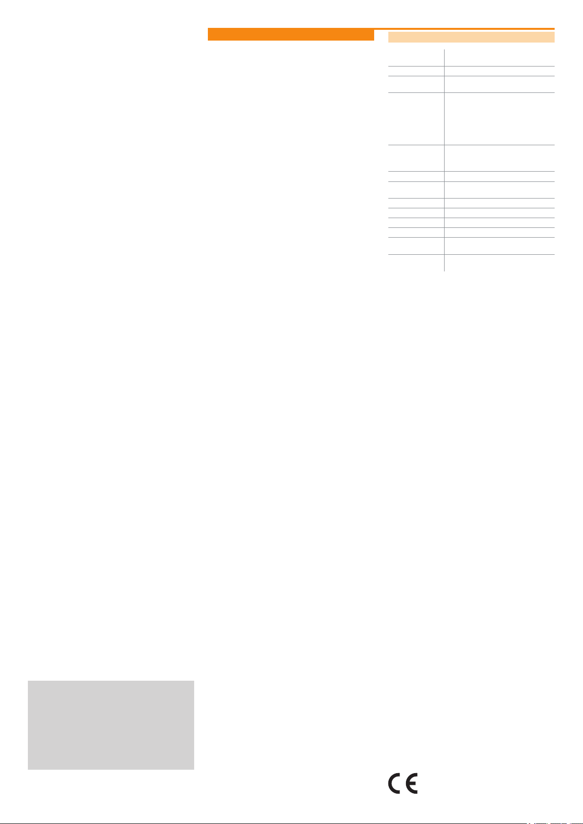
Connecting the control unit
L
N
PE
J
~
~
~
~
L
N
QTi/QT Fit/QTP 5
EVG
QTi/QT Fit/QTP 5
EVG
MULTIeco
Sensor
H
N
K
K
O
L
N
J
L
N
J
MULTIeco
MULTIeco
Sensor
Sensor
H
L
123 4
M
1
4
2 3
H
Left: Individual operation with max. 2 sensors
Right: Networked operation with up to 4 MULTIeco control units
and central presence detection
H Sensor
J Pushbutton
K Lamp
L Y-Connector
M Y-Connector Screw
N To luminaire group 1
O To luminaire group 2
Page 1 of 2
Page 2
Appendix
Technical data
Operating voltage 100-240 VAC / 50-60 Hz
Supply connection L, N (PE not required)
Pushbutton input Potential-free make contact, max. line
Sensor connection Max. 2 sensors, max. line length 25 m
Max. load contact
load capacity
Fuse External 16 A
Power consumption Operation: 1 W
Ambient temperature 0 °C … +50 °C
Adjustable light value 20-600 lux (measured at sensor)
Protection type IP 20
Protection class II
Dimensions
(L x W x H)
Hole distance for
mounting
(DC operation permissible)
length 50 m
Pin assignment:
1: Supply voltage (+ 3.3 V)
2: Light measurement
3: Motion signal
4: Ground
5 A resistive load
Max. number of ECGs: 20 (depends on
the ECG type to be connected)
Standby: < 0.5 W
118 x 30 x 21 mm
110 mm
VI 2011
MULTIeco_ma0611en_we1.02.indd
OSRAM GmbH
Kunden Service Center
Customer-Service-Center (CSC)
Steinerne Furt 62
86167 Augsburg
Germany
Tel : +49 (0) 1803 677 - 200
(kostenpichtig / charges apply)
Fax.: +49 (0) 1803 677 - 202
www.osram.com
www.osram.de
40083214053022
4008321405302
The CE requirements to EN 60928 are fullled. The EMC requirements to EN 61547 are fullled.
Conformity with the relevant EU directives is
conrmed by the CE symbol.
Page 2 of 2
 Loading...