

Page 1
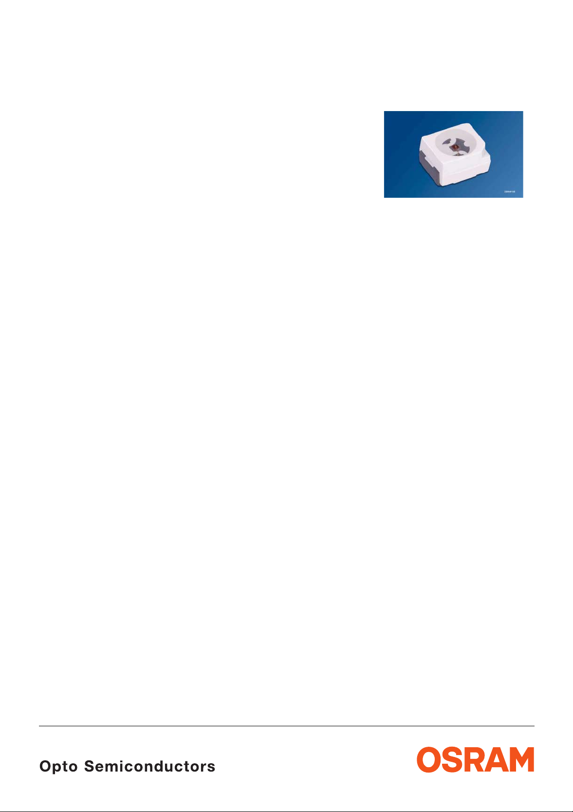
TOPLED
®
LS T670, LO T670, LY T670, LG T670, LP T670
Besondere Merkmale
• Gehäusetyp: weißes P-LCC-2-Gehäuse,
farbloser klarer Verguss
• Besonderheit des Bauteils: extrem breite
Abstrahlcharakteristik; ideal für Hinterleuchtungen
und Einkopplungen in Lichtleiter
• Wellenlänge: 628 nm (super-rot),
606 nm (orange), 587 nm (gelb), 57 0 nm (grün),
560 nm (pure green)
• Abstrahlwinkel: Lambertscher Strahler (120°)
• Technologie: GaAsP (super-rot, orange, gelb,
grün), GaP (pure green)
• optischer Wirkungsgrad: 1,5 lm/W (super-rot,
orange, gelb), 2,5 lm/W (grün),
0,6 lm/W (pure green)
• Gruppierungsparameter: Lich tstärke,
Wellenlänge
• Verarbeitungsmethode: für alle
SMT-Bestücktechniken geeignet
• Lötmethode: IR Reflow Löten und
Wellenlöten (TTW)
• Vorbehandlung: nach JEDEC Level 2
• Gurtung: 8-mm Gurt mit 2000/Rolle, ø180 mm
oder 8000/Rolle, ø330 mm
Features
• package: white P-LCC-2 package, colorless clear
resin
• feature of the device: extremely wide viewing
angle; ideal for backlighting and coupling in light
guides
• wavelength: 628 nm (super-red),
606 nm (orange), 587 nm (y ellow),
570 nm (green), 560 nm (pur e green)
• viewing angle: Lambertian Emitter (120°)
• technology: GaAsP (super-red, orange, yellow,
green), GaP (pure green)
• optical efficiency: 1.5 lm/W (super-red, orange,
yellow), 2.5 lm/W (green), 0.6 lm/W (pure green)
• grouping parameter: luminous intensity,
wavelength
• assembly methods: suitable for all
SMT assembly methods
• soldering me thods: IR reflow soldering and
TTW soldering
• preconditioning: acc. to JEDEC Level 2
• taping: 8 mm tape with 2000/reel, ø180 mm
or 8000/reel, ø330 mm
Anwendungen
• Informationsanzeigen im Innen- und Außenbereich
• optischer Indikator
• Hinterleuchtung (LCD, Handy, Schalter, Tasten,
Displays, Werbebeleuchtung,
Allgemeinbeleuchtung)
• Innenbeleuchtung im Automobilbereich
(z. B. Instrumentenbeleuchtung)
• Markierungsbeleuchtung(z.B.S tufen,Fluchtwege,
u.ä.)
• Einkopplung in Lichtleiter
• Laufschriftanzeigen
• Signal- und Symbolleuchten
2004-04-23 1
Applications
• indoor and outdoor display s
• opticalindicators
• backlighting (LCD, cellular phones, switches, keys,
displays, illuminated advertising, general lighting)
• interior automotive lighting
(e.g. da shboard backlighting)
• marker lights (e.g. steps, exit ways, etc.)
• coupling into light guides
• light writing displays
• signal and symbol luminaire
Page 2
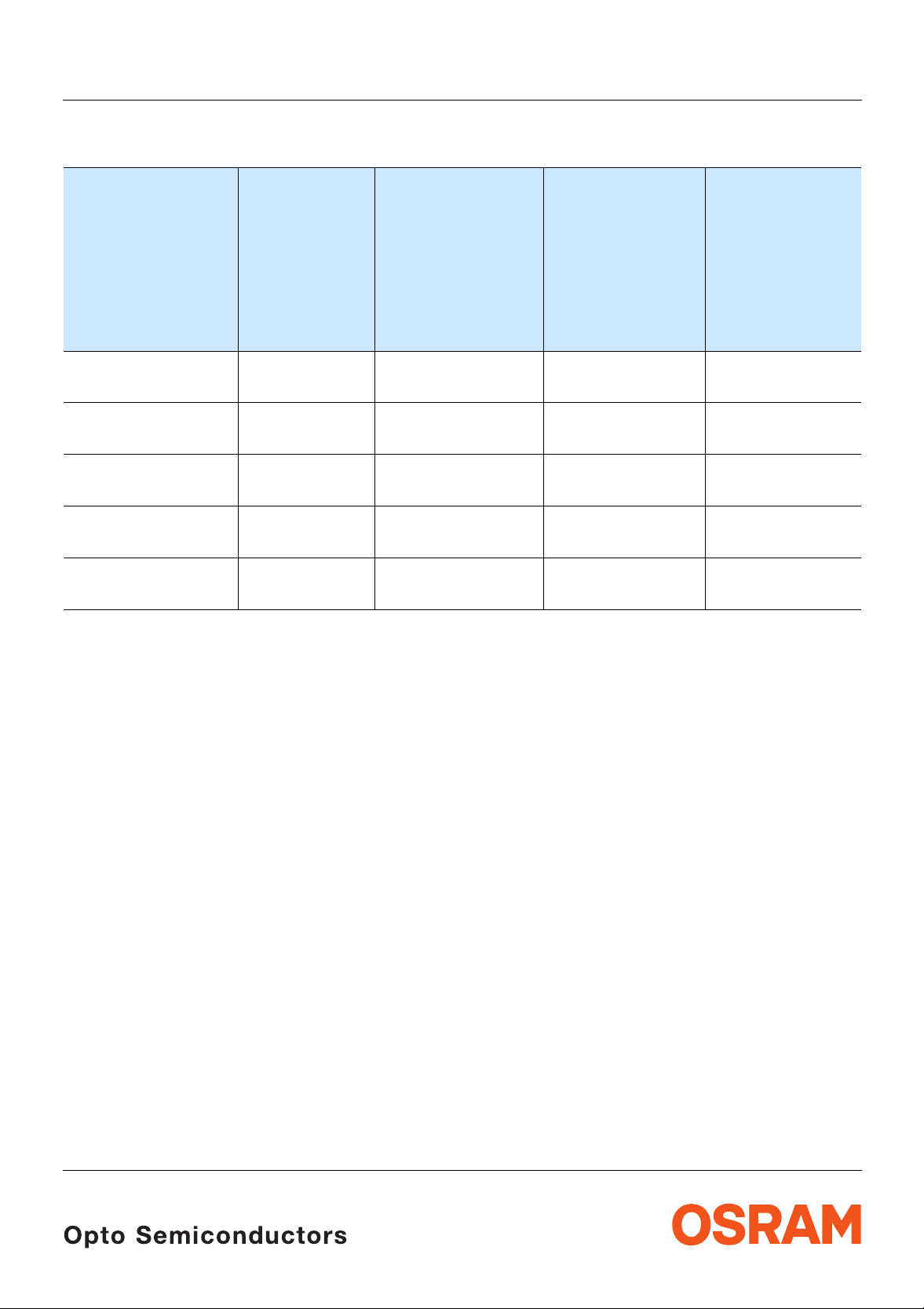
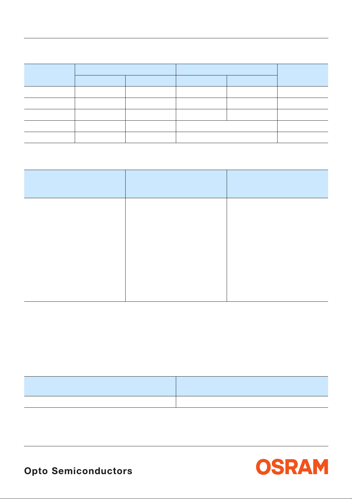
Bestellinformation Ordering Information
Typ
Emissionsfarbe
LS T670, LO T670, LY T670, LG T670, LP T670
Lichtstärke
1)
Seite 15
Lichtstrom
2)
Seite 15
Bestellnummer
Type
LS T670-H2J2-1
LS T670-J2L1-1
LO T670-J1K1-24
LO T670-K1L2-24
LY T670-J1K1-26
LY T670-K1L2-26
LG T670-K1L2-1
LG T670-L1M2-1
LP T670-G1H1-1
LP T670-H1J2-1
Color of
Emission
Luminous
Intensity
I
=10mA
F
I
(mcd)
V
super-red 3.55 ... 7.10
5.60 ... 14.00
orange 4.50 ... 9.00
7.10 ... 18.00
yellow 4.50 ... 9.00
7.10 ... 18.00
green 7.10 ... 18.00
11.20 ... 28.00
pure green 1.80 ... 3.55
2.80 ... 7.10
Anm.: - 1 Gesamter Farbbereich (siehe Seite 4)
-24 Gesamter Farbbereich, Lieferung in Einzelgruppen (siehe Seite 5)
-26 Gesamter Farbbereich, Lieferung in Einzelgruppen (siehe Seite 5)
1)
page 15
Luminous
2)
Flux
I
Φ
page 15
=10mA
F
(mlm)
V
15 (typ.)
28 (typ.)
20 (typ.)
36 (typ.)
20 (typ.)
36 (typ.)
36 (typ.)
56 (typ.)
7(typ.)
14 (typ.)
Ordering Code
Q62703Q5094
Q62703Q5095
Q62703Q5046
Q62703Q5047
Q62703Q5132
Q62703Q5133
Q62703Q4503
Q62703Q5011
Q65110A0323
Q65110A0324
Note: - 1 Total color tolerance range (see page 4)
-24 Total c olor tolerance range, delivery in single groups (see page 5)
-26 Total c olor tolerance range, delivery in single groups (see page 5)
2004-04-23 2
Page 3
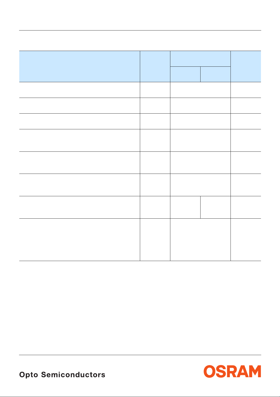
Grenzwerte
Maximum Ratings
LS T670, LO T670, LY T670, LG T670, LP T670
Bezeichnung
Parameter
Betriebstemperatur
Operating temperature range
Lagertemperatur
Storage temperature range
Sperrschichttemperatur
Junction temperature
Durchlassstrom
Forward current
T
=25°C)
(
A
Stoßstrom
Surge current
t ≤ 10 µs, D = 0.005, T
3)
Sperrspannung
Reverse voltage
Seite 15
3)
page 15
=25°C
A
(TA=25°C)
Symbol
Symbol
T
op
T
stg
T
j
I
F
I
FM
V
R
Wert
Value
LS, LO,
LP
LY, LG
– 40 … + 100 °C
– 40 … + 100 °C
+ 100 °C
30 mA
0.5 A
12 V
Einheit
Unit
Leistungsaufnahme
Power consumption
T
=25°C)
(
A
Wärmewiderstand
Thermal resistance
Sperrschicht/Umgebung
4)
Junction/ambient
page 15
Sperrschicht/Lötpad
Junction/soldering point
4)
Seite 15
P
R
R
tot
th JA
th JS
95 90 mW
400
180
K/W
K/W
2004-04-23 3
Page 4
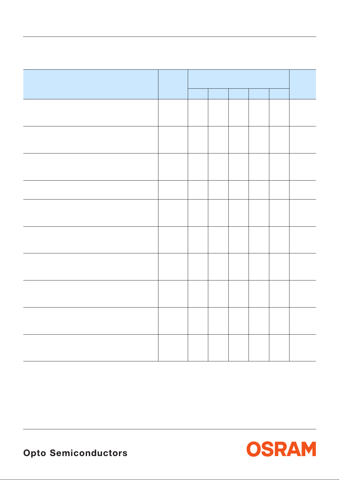
Kennwerte
Characteristics
T
=25°C)
(
A
Bezeichnung
Parameter
LS T670, LO T670, LY T670, LG T670, LP T670
Symbol
Symbol
LS LO LY LG LP
Wert
Value
Einheit
Unit
Wellenlänge des emittierten Lichtes (typ.)
Wavelength at peak emission
I
=10mA
F
5)
Dominantwellenlänge
Dominant wavelength
I
=10mA
F
Spektrale B andbreite bei 50 %
Spectral bandwidth at 50 %
I
=10mA
F
Abstrahlwinkel bei 50 %
Viewing angle at 50 %
Durchlassspannung
Forward voltage
I
=10mA
F
6)
5)
6)
Seite 15
page 15
Seite 15
page 15
I
rel max
I
rel max
I
(Vollwinkel) (typ.)
V
I
V
(typ.)
(typ.)
(max.)
Sperrstrom (typ.)
Reverse current (max.)
V
=12V
R
Temperaturkoeffizient von
Temperature coefficient of
I
=10mA;–10°C ≤ T ≤ 100°C
F
Temperaturkoeffizient von
Temperature coefficient of
I
=10mA;–10°C ≤ T ≤ 100°C
F
Temperaturkoeffizient von
Temperature coefficient of
I
=10mA;–10°C ≤ T ≤ 100°C
F
λ
peak
λ
peak
λ
dom
λ
dom
V
F
V
F
(typ.)
(typ.)
(typ.)
Optischer Wirkungsgrad (typ.)
Optical efficiency
I
=10mA
F
* Einzelgruppen siehe Seite 5
Individual groups on page 5
λ
λ
∆λ
peak
dom
635 610 586 572 557 nm
628±6606*
–6/+3
587*
–7/+8
570±6560±6nm
45 40 45 25 22 nm
2ϕ 120 120 120 120 120 Grad
deg.
V
V
I
R
I
R
TC
TC
TC
η
opt
F
F
λpeak
λdom
V
2.0
2.5
0.01100.01100.01100.01100.01
2.0
2.5
2.0
2.5
2.0
2.5
2.0
2.5VV
10
µA
µA
0.11 0.12 0.10 0.11 0.11 nm/K
0.07 0.07 0.07 0.07 0.05 nm/K
– 1.9 – 1.9 – 1.9 – 1.4 – 2.1
mV/K
1.5 1.5 1.5 2.5 0.6 lm/W
2004-04-23 4
Page 5
LS T670, LO T670, LY T670, LG T670, LP T670
Wellenlängengruppen (Dominantwellenlänge)
Wavelength Groups (Dominant Wavelength)
5)
5)
Seite 15
page 15
Gruppe
Group
min. max. min. max.
yellow orange Einheit
2 580 583 600 603 nm
3 583 586 603 606 nm
4 586 589 606 609 nm
5 589 592 nm
6 592 595 nm
Helligkeits-Gruppierungsschema Brightness Groups
Helligkeitshalbgruppe
Brightness Half Gr oup
G1
G2
H1
H2
J1
J2
K1
K2
L1
L2
M1
M2
1)
Lichtstärke
Seite 15
Luminous Intensity
I
(mcd)
V
1.80 ... 2.24
2.24 ... 2.80
2.80 ... 3.55
3.55 ... 4.50
4.50 ... 5.60
5.60 ... 7.10
7.10 ... 9.00
9.00 ... 11.20
11.20 ... 14.00
14.00 ... 18.00
18.00 ... 22.40
22.40 ... 28.00
1)
page 15
Lichtstrom
Luminous Flux
Φ
(mlm)
V
6.0 (typ.)
7.6 (typ.)
8.5 (typ.)
12.0 (typ.)
15.0 (typ.)
19.0 (typ.)
24.0 (typ.)
30.0 (typ.)
40.0 (typ.)
50.0 (typ.)
60.0 (typ.)
75.0 (typ.)
2)
Seite 15
2)
page 15
Unit
Anm.: Die Standardlieferform von Serientypen beinhaltet eine untere bzw. eine obere Familiengruppe. Diese
besteht aus 3 bzw. 4 Helligkeitshalbgruppen besteht. Einzelne Helligkeitshalbgruppen sind nicht bestellbar.
Note: The standard shipping format for serial types includes a lower or upper family group of 3 or 4 individual
brightness half groups. Individual brightness half groups cannot be ordered.
Gruppenbezeichnung auf Etikett
Group Name on Label
Beispiel: K1-3
Example: K1-3
Helligkeitshalbgruppe
Brightness Half Gr oup
Wellenlänge
Wavelength
K1 3
Anm.: In einer Verpackungseinheit / Gurt ist immer nur eine Gruppe für jede Selektion enthalten.
Note: No packing unit / tape ever contains more than one group for each selection.
2004-04-23 5
Page 6

LS T670, LO T670, LY T670, LG T670, LP T670
2)
Relative spektrale Emission
Relative Spectral Emission
V(λ) = spektrale Augenempfindlichkeit / Standard eye response curve
I
= f (λ); TA=25°C; IF=10mA
rel
100
%
I
rel
80
60
2)
page 15
Seite 15
V
λ
OHL01697
40
20
0
400 450 500 550 600 650 700
Abstrahlcharakteristik
2)
Radiation Characteristic
I
= f (ϕ); TA=25°C
rel
50˚
60˚
Seite 15
2)
page 15
0˚10˚20˚40˚ 30˚
ϕ
pure-green
green
1.0
0.8
0.6
yellow
orange
super-red
nm
λ
OHL01660
0.4
70˚
0.2
80˚
90˚
0
100˚
1.0 0.8 0.6 0.4
0˚ 20˚ 40˚ 60˚ 80˚ 100˚ 120˚
2004-04-23 6
Page 7

LS T670, LO T670, LY T670, LG T670, LP T670
Durchlassstrom
Forward Current
I
= f (VF); TA=25°C
F
2
10
I
mA
F
1
10
5
0
10
5
-1
10
1.0 1.4 1.8 2.2 2.6 3.0 3.4
2) 7)
2) 7)
Seite 15
page 15
pure-green
super-red
orange/yellow
green
OHL02145
V
V
F
2) 7)
Relative Lichtstärke
Seite 15
Relative Luminous Intensity
I
V/IV(10 mA)
I
V (10 mA)
Relative Lichtstärke
= f (IF); TA=25°C
1
10
I
V
0
10
5
-1
10
5
-2
10
0
10
green
yellow
pure-green
super-red
orange
5110
2)
Seite 15
Relative Luminous Intensity
I
/ IV(25 °C)= f (Tj); IF=10mA
V
2.0
2) 7)
2)
page 15
page 15
OHL00993
OHL02150
2
10mA
I
F
2004-04-23 7
I
V
(25 ˚C)
I
V
1.6
1.2
0.8
orange
super-red
pure-green
0.4
0.0
0 20 40 60 80 100
yellow
green
˚C
T
j
Page 8

Maximal zulässiger Durchlassstrom
Max. Permissible Forward Current
I
= f (TA)
F
40
I
F
mA
30
T
20
10
temp. ambient
Τ
A
Τ
temp. solder point
S
OHL00962
A
LS T670, LO T670, LY T670, LG T670, LP T670
T
S
0
0 20 40 60 80 C 100
T
Zulässige Impulsbelastbarkeit
I
F
= f (tp)
Permissible Pulse Handling Capability
Duty cycle
3
10
I
F
mA
2
10
5
D = parameter, T
t
P
D
=
T
D
=
0.2
0.5
DC
t
P
0.005
0.01
0.02
0.05
0.1
=25°C
A
T
OHL01686
I
F
1
10
t
p
s10-510-410-310-210-110010
1
2004-04-23 8
Page 9

Maßzeichnung
8)
Package Outlines
Seite15
8)
page 15
LS T670, LO T670, LY T670, LG T670, LP T670
3.0 (0.118)
2.6 (0.102)
2.3 (0.091)
2.1 (0.083)
3.0 (0.118)
3.4 (0.134)
Cathode marking
0.1 (0.004) (typ.)
(2.4) (0.095)
3.7 (0.146)
0.18 (0.007)
0.12 (0.005)
3.3 (0.130)
2.1 (0.083)
1.7 (0.067)
4˚±1
0.5 (0.020)
1.1 (0.043)
0.9 (0.035)
0.7 (0.028)
0.6 (0.024)
0.4 (0.016)
Kathodenkennung: abgeschrägte Ecke
Cathode mark: bevelled edge
Gewicht / Approx. weight: 35 mg
GPLY6724
8)
Gurtung / Polarität und Lage
Method of Taping / Polarity and Orientation
Seite15
8)
page 15
4 (0.157)1.5 (0.059)
2.9 (0.114)
2004-04-23 9
Verpackungseinheit 2000/Rolle, ø180 mm
oder 8000/Rolle, ø330 mm
Packingunit 2000/reel,ø180 mm or 8000/reel,
ø330 mm
2 (0.079)
C
8 (0.315)
1.75 (0.069)
A
4 (0.157)
3.5 (0.138)
3.6 (0.142)
OHAY2271
Page 10

Empfohlenes Lötpaddesign
Recommended Solder Pad
8) 9)
8) 9)
Seite 15
page 15
2.6 (0.102)
LS T670, LO T670, LY T670, LG T670, LP T670
IR-Reflow Löten
IR Reflow Soldering
2.6 (0.102)
1.5 (0.059)
4.5 (0.177)
1.5 (0.059)
Padgeometrie für
verbesserte Wärmeableitung
Paddesign for
improved heat dissipation
Lötstopplack
Solder resist
Empfohlenes Lötpaddesignverwendbar fürTOPLED
8)
IR Reflow Löten
Seite 15
®
Cu-Fläche > 16 mm
Cu-area > 16 mm
OHLPY970
und Power TOPLED
Recommended Solder Pad useable for TOPLED®and Power TOPLED
8)
IR Reflow Soldering
page 15
Padgeometrie für
verbesserte Wärmeableitung
Paddesign for
improved heat dissipation
2.3 (0.091)
0.8 (0.031)
Anode
3.3 (0.130)
Fläche darf elektrisch nicht beschaltet werden.
Do not use this area for electrical contact.
3.3 (0.130)
4.5 (0.177)
2
2
®
®
1.1 (0.043)
3.7 (0.146)
0.7 (0.028)
Fläche darf elektrisch nicht beschaltet werden.
Do not use this area for electrical contact.
1.5 (0.059)
Lötstoplack
Solder resist
2004-04-23 10
11.1 (0.437)
Kathode/
Cathode
2
_
Cu Fläche / 16 mm per pad
Cu-area
<
OHLPY440
Page 11

LS T670, LO T670, LY T670, LG T670, LP T670
Lötbedingungen Vorbehandlung nach JEDEC Level 2
Soldering Conditions Preconditioning acc. to JEDEC Level 2
IR-Reflow Lötprofil (nach IPC 9501)
IR Reflow Soldering Profile (acc. to IPC 9501)
300
C
250
T
240-245 C
10-40 s
200
120 to 180 s
150
100
defined for Preconditioning: up to 6 K/s
ramp-up rate up to 6 K/s
50
defined for Preconditioning: 2-3 K/s
0
0
50 100 150 200 250
Wellenlöten (TTW) (nach CECC 00802) TTW Soldering (acc. to CECC 00802)
300
C
250
T
235 C
200
150
CC... 130100
100
C... 260
1. Welle
1. wave
ca 200 K/s
10 s
5 K/s
2. Welle
2. wave
2 K/s
OHLY0597
183 C
ramp-down rate up to 6 K/s
s
t
OHLY0598
Normalkurve
standard curve
Grenzkurven
limit curves
Zwangskühlung
2 K/s
50
0
0
50 100 150 200 250
forced cooling
2004-04-23 11
s
t
Page 12

Barcode-Produkt-Etikett (BPL) Barcode-Product-Label (BPL)
LS T670, LO T670, LY T670, LG T670, LP T670
Gurtverpackung Tape and Reel
OSRAM Opto
Semiconductors
(6P) BATCH NO: Batch Number
Bar Code
Lot Number(1T) LOT NO: (9D) D/C: Date Code
Bar Code
(X) PROD NO: Product Code
D
0
P
0
P
2
Bin1: Bin Information Color 1
Lx xxxx
Product Name
Product Quantity per Reel(Q)QTY:
Bar Code
Sample
W
1
±0.25
13.0
FE
A
N
W
Bin2:
Bin3:
Temp ST
ML
2
245 C R
260 C T2
Additional TEXT
R077 DEMY
PACKVAR: Packing Type
X - X - X(G) GROUP:
Forward Voltage Rank
Wavelength Rank
Brightness Rank
OHA02043
P
1
Direction of unreeling
W
2
Label
Gurtvorlauf:
Leader:
Gurtende:
Trailer:
Direction of unreeling
400 mm
400 mm
160 mm
160 mm
OHAY0324
Tape dimensions in mm (inch)
W P
+0.3
8
– 0.1
0
4 ± 0.1
(0.157 ± 0.004)
P
1
4 ± 0.1
(0.157 ± 0.004)
P
2
2 ± 0.05
(0.079 ± 0.002)
D
0
1.5 + 0.1
(0.059 + 0.004)
E F
1.75 ± 0.1
(0.069 ± 0.004)
3.5 ± 0.05
(0.138 ± 0.002)
Reel dimensions in mm (inch)
A W N
min
W
1
W
2max
180 (7) 8 (0.315) 60 (2.362) 8.4 + 2 (0.331 + 0.079) 14.4 (0.567)
330 (13) 8 (0.315) 60 (2.362) 8.4 + 2 (0.331 + 0.079) 14.4 (0.567)
2004-04-23 12
Page 13

LS T670, LO T670, LY T670, LG T670, LP T670
Trockenverpackung und Materialien Dry Packing Process and Materials
Moisture-sensitive label or print
L
E
V
l
E
e
e
b
L
a
se
.
l
,
)
e
k
H
d
n
o
la
R
c
b
(
r
f
I
a
y
t
b
.
i
d
H
i
R
m
u
%
h
0
e
6
e
/
v
i
g
d
t
C
a
e
˚
a
r
l
k
a
0
c
e
r
S
r
f
3
a
N
E
s
R
n
p
_
<
V
i
n
%
I
i
f
O
k
0
o
T
s
a
o
t
T
I
a
r
t
9
IO
e
.
s
S
u
s
C
n
d
)
r
r
<
p
n
o
e
N
o
U
(
e
T
o
u
s
t
o
d
c
E
S
g
N
U
a
O
E
b
C
A
R
I
s
U
i
M
T
h
C
E
T
S
<
I
S
t
O
a
O
M
T
s
a
h
P
h
t
t
i
n
O
u
s
o
q
e
m
c
e
i
r
e
v
4
o
d
e
2
,
o
d
:
c
,
g
w
r
d
a
o
l
a
e
b
f
e
b
n
e
d
r
e
m
e
e
i
l
p
t
e
e
a
o
s
r
s
e
a
o
,
s
.
i
s
h
k
b
o
l
H
p
n
,
g
n
-
i
F
a
n
g
r
R
a
a
l
i
n
e
o
b
C
b
h
i
f
t
i
p
%
i
k
l
f
s
r
.
.
i
I
t
a
0
a
f
o
p
w
l
h
v
t
e
1
b
t
e
,
a
m
d
_
<
r
m
,
h
e
c
e
e
w
i
r
e
t
t
t
t
d
i
S
t
o
d
f
o
a
n
e
l
u
y
.
f
r
n
n
u
D
i
A
I
q
d
1
d
e
o
u
.
r
e
E
s
o
e
y
i
r
r
q
2
t
J
b
i
M
/
o
e
s
b
d
t
)
r
i
C
e
2
a
S
s
c
P
r
m
i
i
I
)
o
u
v
b
g
e
e
H
a
n
c
i
D
e
)
2
n
t
k
.
a
)
e
a
a
r
3
b
d
b
e
e
f
l
f
I
m
e
a
i
r
.
t
e
v
4
s
d
e
n
L
g
a
a
e
L
r
B
e
t
u
e
t
r
a
s
u
e
i
t
D
r
o
s
u
i
t
M
o
s
u
i
t
M
o
s
i
M
o
M
r
H
i
d
,
c
o
D
t
g
n
s
i
u
o
e
r
C
2
n
H
j
a
d
o
i
c
˚
u
7
b
s
n
8
H
o
e
5
C
u
s
o
t
4
˚
e
s
4
e
H
c
a
±
c
2
0
m
d
e
e
y
6
i
o
4
r
t
C
b
r
h
˚
m
e
o
l
r
i
t
p
t
l
i
t
.
i
o
3
c
m
t
e
)
r
i
w
o
2
w
t
a
n
l
o
C
l
f
m
t
t
i
˚
r
e
.
F
o
a
l
t
t
l
a
o
e
c
a
a
r
i
r
F
l
o
t
d
v
l
o
u
e
n
:
a
F
o
f
d
l
b
4
i
e
e
w
e
l
r
a
F
,
d
l
o
i
5
c
l
e
g
a
n
l
o
v
e
s
n
5
r
i
e
e
i
e
b
t
l
p
h
v
6
L
e
n
e
e
t
e
l
w
e
v
u
e
e
a
L
k
e
r
e
o
s
d
v
a
%
u
e
L
l
t
r
m
e
b
0
s
a
u
e
L
i
r
1
t
e
r
e
r
o
o
s
e
u
s
f
i
>
t
o
r
f
M
,
o
s
u
s
3
i
k
i
e
t
3
M
o
s
n
i
d
0
a
r
M
o
l
b
D
M
f
r
T
i
(
a
S
r
s
e
a
J
k
s
Y
e
r
e
C
1
u
e
Y
E
o
>
1
W
H
e
4
8
m
e
6
i
t
1
m
:
e
r
i
t
d
o
m
e
r
e
i
o
t
l
o
n
m
i
r
F
o
e
t
l
o
p
r
F
o
o
l
o
F
o
l
1
l
F
2
e
a
l
2
e
l
v
3
e
e
l
v
e
e
v
L
e
L
e
r
M
A
R
S
O
Desiccant
Anm.: Feuchteempfindliche Produkte sind verpackt in einem Trockenbeutel zusammen mit einem Trockenmittel und
einer Feuchteindikatorkarte
Bezüglich Trockenverpackung finden Sie weitere Hinweise im Internet und in unserem Short Form Catalog im
Kapitel “Gurtung und Verpackung” unter dem Punkt “Trockenverpackung”. Hier sind Normenbezüge, unter
anderem ein Auszug der JEDEC-Norm, enthalten.
Note: Moisture-senisitve product is packed in a dry bag containing desiccant and a humidity card.
Regarding dry pack you will find further information in the internet and in the Short Form Catalog in chapter
“Tape and Reel” under the topic “Dry Pack”. Here you will also find the normative references like JEDEC.
Kartonverpackung und Materialien Transportation Packing and Materials
Barcode label
Do not eat.
Avoid metal contact.
Discard if circles overrun.
bag opening.
Please check the HIC immidiately after
check dot
WET
Comparator
bake units
15%
examine units, if necessary
If wet,
bake units
10%
examine units, if necessary
If wet,
change desiccant
5%
parts still adequately dry.
If wet,
MIL-I-8835
Humidity Indicator
OSRAM
Humidity indicator
Barcode label
OHA00539
E
V
E
L
f
I
h
e
v
i
d
t
e
a
r
l
a
c
e
r
S
r
f
a
E
s
R
n
p
i
V
n
%
I
i
O
k
0
o
T
a
t
a
T
I
9
t
e
S
C
d
n
<
p
n
e
N
o
(
U
t
o
d
c
i
E
c
D
g
t
n
i
e
S
n
g
N
j
a
i
d
a
b
s
n
O
E
C
u
b
s
o
˚
C
R
s
e
I
c
s
c
U
i
0
e
y
M
o
4
T
h
r
CAUTION
b
r
E
o
T
l
S
p
<
t
l
I
S
.
i
3
t
c
t
)
O
2
w
n
a
a
O
C
f
t
t
˚
e
M
l
s
T
t
a
a
a
h
a
P
h
l
t
d
v
t
i
e
n
O
:
a
u
s
f
b
o
i
e
w
q
e
r
a
,
l
o
m
c
c
e
l
i
g
n
o
r
e
e
v
4
n
r
e
i
o
b
d
e
2
t
p
h
,
o
d
:
n
e
w
e
c
,
g
u
w
e
k
r
d
a
o
o
s
d
l
a
%
a
e
b
f
l
m
b
e
0
b
n
e
a
d
r
r
1
e
e
m
e
e
e
i
r
o
l
p
e
t
s
f
>
e
o
a
o
s
f
,
r
s
s
3
e
a
k
i
e
o
,
s
.
i
3
s
h
n
b
k
o
d
l
0
H
p
a
,
n
r
g
n
l
-
i
F
g
n
a
a
r
a
R
b
i
l
D
n
e
o
b
f
C
i
h
b
f
r
T
i
t
i
p
%
k
i
l
(
f
r
s
.
.
a
S
i
I
t
a
0
a
f
-
o
p
e
w
l
h
t
v
e
1
a
b
J
t
e
Y
a
,
m
d
e
_
r
<
m
,
h
e
c
e
C
e
i
w
1
r
Y
e
t
t
t
t
d
i
S
t
d
o
E
f
o
a
n
e
l
u
>
y
.
1
W
f
r
n
n
D
u
i
A
I
q
d
1
d
e
e
4
o
u
.
r
e
E
s
o
e
8
y
i
r
q
r
t
2
J
m
b
e
i
M
6
/
i
e
o
t
s
b
d
1
t
)
r
:
m
i
C
e
e
2
r
i
a
S
t
d
s
c
P
o
r
m
i
m
i
e
I
)
e
r
i
o
o
u
t
v
l
b
n
o
g
m
e
e
i
r
H
F
a
e
o
n
t
c
l
i
o
D
e
)
2
p
n
r
t
k
F
o
.
a
o
l
)
e
o
a
a
r
3
b
F
o
d
b
e
l
1
e
f
l
f
l
F
I
m
2
e
a
i
e
a
r
.
t
l
e
v
2
4
e
s
d
e
l
v
3
n
L
g
e
e
l
a
v
a
e
L
e
r
e
B
e
v
t
u
e
L
t
r
e
a
s
u
e
L
i
t
D
r
o
s
e
u
i
t
r
M
o
s
u
i
t
M
o
s
i
M
o
M
Barcode label
S
L
lt
u
M
8
o
t
9
:
s
9
p
r
/C
1
o
D
O
t
)
2
c
D
0
9
u
M
0
(
d
1
A
n
2
o
:
R
4
c
O
3
i
S
N
2
m
O
1
H
e
C
H
S
T
A
G
B
3
)
2
P
1
6
:
(
O
245
N
T
1
O
L
0
)
0
T
1
11
(
:
O
N
D
O
R
P
)
X
(
Packing
Sealing label
2004-04-23 13
L
l
e
e
b
e
a
s
.
l
)
,
e
k
H
d
n
o
a
l
R
c
(
b
r
a
y
t
b
i
.
d
H
i
R
m
u
%
0
6
e
/
g
C
a
˚
k
0
3
_
<
f
o
s
r
o
,
C
˚
e
5
t
a
±
d
C
˚
h
t
i
w
l
.
a
e
c
i
r
t
u
n
d
4
e
e
l
d
i
5
e
l
v
s
i
e
e
l
v
L
e
e
t
e
v
e
a
L
r
e
v
u
e
L
t
r
e
s
u
e
L
i
t
r
o
s
e
u
i
t
r
M
o
s
u
i
t
M
o
s
i
M
o
M
r
s
k
s
r
e
u
e
o
H
to
p
rs
O
cto
M
du
A
210021998
R
icon
S
m
O
Se
123G
(6P) BATCH NO:
(1T) LOT NO:
0
2
0
1
2
-
-
P
1
-
:
1
Q
T
:
in
S
2
B
:
p
in
R
3
B
m
in
6
e
R
C
B
T
7
0
C
2
6
R
D
2
L
0
C
4
T
M
E
2
0
L
Y
6
2
2
P
a
2
O
io
3
T
t
i
i
d
d
A
0
R
4
4
1
0
0
0
0
2
:
Y
T
Q
)
Q
(
Muster
.
)
e
d
o
c
e
m
i
t
m
r
i
t
o
r
o
l
o
r
F
o
l
o
F
o
l
o
F
o
l
F
a
5
6
l
e
34
12
H
(X) PROD NO:
M
T
E
T
D
X
E
T
l
8
a
1
n
R
:
R
7
A
7
V
K
C
A
P
U
O
R
G
)
G
(
s
r
u
s
r
o
u
s
r
H
o
s
u
r
2
H
o
u
7
8
H
o
4
4
H
2
e
6
e
m
e
i
t
m
i
t
r
Bin1: P-1-20
Bin2: Q-1-20
Bin3:
D
ML
E
Y T676
2
PL
LS
ulti TO
M
144
0
(9D) D/C:
00
20
(Q)QTY:
245
1
Muster
0
0
11
Y
1
-
Q
+
1
-
P
:
P
Barcode label
Temp ST
220 C R
DEMY
240 C R
260 C RT
8
2a
1
R
-1
3
Additional TEXT
-1+Q
R077
P
PACKVAR:
(G) GROUP:
OSRAM
OHA02044
Page 14

LS T670, LO T670, LY T670, LG T670, LP T670
Revision H istory: 2004-04-23
Previous Version: 2003-12-17
Page Subjects (major changes since last revision) Date of change
5 Wavelength grouping
2 wavelength grouping for yellow and orange
9 change of weight from 40 mg to 35 mg 2002-06-28
14 annotations 2002-07-23
®
13 recomm. solder pad for TOPLED
3, 4 value (reverse voltage from 5 V to 12 V) 2002-09-18
2 Ordering Code 2002-09-16
and Power TOPLED®(OHLPY440) 2002-08-05
7 diagram relative luminous intensity
f (I
) 2003-03-13
F
1 ESD norm 2003-09-03
3 ambient temperature 2003-09-03
all new template 2003-10-29
Attention please!
The information describes the type of component and shall not be considered as assured characteristics.
Terms of delivery and rights to change design reserved. Due to technical requirements components may contain
dangerous substances. For information on the types in question please contact our Sales Organization.
If printed or downloaded, please find the latest version in the Internet.
Packing
Please use the recycling operators known to you. We can also help you – get in touch with your nearest sales office.
By agreement we will take packing material back, if it is sorted. You must bear the costs of transport. For packing
material that is returned to us unsorted or which we are not obliged to accept, we shall have to invoice you for any costs
incurred.
Components used in life-support devices or systems must be expressly authorized for such purpose! Critical
components
OSRAM OS.
2004-04-23 14
10) page 15
may only be used in life-support devices or systems
11) page 15
with the express written approval of
Page 15

LS T670, LO T670, LY T670, LG T670, LP T670
Fußnoten:
1)
Helligkeitswerte werden mit einer
Stromeinprägedauer von 25 ms und einer
Genauigkeit von ± 11% ermittelt.
2)
Wegen der besonderen Prozessbedingungen bei der
Herstellung von LED können typische oderabgeleitete
technische Parameter nur aufgrund statistischer
Werte wiedergegeben werden. Diese stimmen nicht
notwendigerweise mit den Werten jedes einzelnen
Produktes überein, dessen Werte sich von typischen
und abgeleiteten Werten oder typischen Kennlinien
unterscheiden können. Falls erforderlich, z.B.
aufgrund technischer Verbesserungen, werden diese
typischen Werte ohne weitere Ankündigung geändert.
3)
Die LED kann kurzzeitig in Sperrichtung betrieben
werden.
4)
Montage auf PC-Board FR 4 (Padgröße ≥ 16 mm2)
5)
Wellenlängen werden mit einer Stromeinprägedauer
von 25 ms und einer Genauigkeit von ±1 nm ermittelt.
6)
Spannungswerte werden mit einer
Stromeinprägedauer von 1 ms und einer Genauigkeit
von ±0,1 V ermittelt.
7)
Im gestrichelten Bereich der Kennlinien muss mit
erhöhten Helligkeitsunterschieden zwischen
Leuchtdioden innerhalb einer Verpackungseinheit
gerechnet werden.
8)
Maße werden wie folgt angegeben: mm (inch)
9)
Gehäuse hält TTW-Löthitze aus nach CECC 00802
10)
Ein kritisches Bauteil ist ein Bauteil, das in
lebenserhaltenden Apparaten oder Systemen
eingesetzt wird und dessen Defekt voraussichtlich zu
einer Fehlfunktion dieses lebenserhaltenden
Apparates oder Systems führen wird oder die
Sicherheit oder Effektivität dieses Apparates oder
Systems beeinträchtigt.
11)
Lebenserhaltende Apparate oder Systeme sind für
(a) die Implantierung in den menschlichen Körper
oder
(b) für die Lebenserhaltung bestimmt.
Falls sie versagen, kann davon ausgegangen werden,
dass die Gesundheit und das Leben des Patienten in
Gefahr ist.
Remarks:
1)
Brightness groups are tested at a current pulse
duration of 25 ms and a tolerance of ± 11%.
2)
Due to the special conditions of the manufacturing
processes of LED, the typical data or calculated
correlations of technical parameters can only reflect
statistical figures. These do not necessarily
correspond to the actual parameters of each single
product, which could differ from the typical data and
calculated correlations or the typical characteristic
line. If requested, e.g. because of technical
improvements, these typ. data will be changed without
any further notice.
3)
Driving the LED in reverse direction is suitable for
short term application.
4)
MountedonPCboardFR4(padsize≥ 16 mm2)
5)
Wavelengths are tested at a current pulse duration of
25 ms and a tolerance of ±1 nm.
6)
Forward voltages are tested at a current pulse
duration of 1 ms and a tolerance of ±0.1 V.
7)
In the range where the line of the graph is broken, you
must expect higher brightness differences between
single LEDs within one packing unit.
8)
Dimensions are specified as follows: mm (inch).
9)
Package able to withstand TTW-soldering heat acc. to
CECC 00802
10)
A critical component is a component used in a
life-support device or system whose failure can
reasonably be expected to cause the failure of that
life-support device or system, or to affect its safety or
the effectiveness of that device or system.
11)
Life support devices or systems are intended
(a) to be implanted in the human body,
or
(b) to support and/or maintain and sustain human life.
If they fail, it is reasonable to assume that the health
and the life of the user may be endangered.
Published by
OSRAM Opto Semiconductors GmbH
Wernerwerkstrasse 2, D-93049 Regensburg
www.osram-os.com
© All Rights Reserved.
2004-04-23 15
 Loading...